1
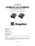
SDH86MB Micro-stepping Motor Driver
IMTT
www.imttusa.com
SDH86MB Micro-stepping Stepper Motor Driver
User Manual
Innovative Materials Testing Technologies, Inc.
3141 W. Torreys Peak Drive, Superior, CO 80027, USA Phone: 303-554-8000 Fax: 303-554-8001 Email: [email protected]
1/13
IMTT
SDH86MB Micro-stepping Motor Driver
www.imttusa.com
Features
• Output current up to 8.28 A
• Supply voltage up to +80VDC
• Up to 1/50 micro step resolution with 16 selectable micro step setup
• Increased torque at high speed
• Suitable for 2-phase and 4-phase step motors with peak current < 8.2A
• Dip switch to set 8 different current values
• Input pulse frequency up to 200kHz
• Optically isolated input signals
• Automatically standstill current reduction
• Over voltage, Over Current, Short Circuit protection
• Bipolar constant current chopping drive circuit
Introduction
The SD2H86MB is a cost effective micro-stepping stepper motor driver based on new developed
technology. It is suitable for driving 2-phase 4-phase hybrid stepping motors .By using the advanced
bipolar constant-current shopping technique, it can output more torque at high speed from the same
motor, compared with traditional drivers, such as L/R drivers. Its 3-state current control technology
allows coil currents to be well controlled and with relatively small current ripple, therefore less motor
heating is achieved.
Specifications and Operating Environment
Electrical Specifications (Tj=25℃)
Parameters
SD2H86MB
Min
Typical
Max
Unit
Output current
1.82
-
8.28 (peak)
A
Supply voltage((DC)
20
68
80
VDC
Logic signal current
6
10
30
mA
Pulse input frequency
0
-
200
KHz
Isolation resistance
500
Control signal input high
3.6
5
5.5
VDC
Control signal input low
-5.5
0
0.3
VDC
mΩ
Innovative Materials Testing Technologies, Inc.
3141 W. Torreys Peak Drive, Superior, CO 80027, USA Phone: 303-554-8000 Fax: 303-554-8001 Email: [email protected]
2/13
IMTT
SDH86MB Micro-stepping Motor Driver
www.imttusa.com
Operating Environment and other Specifications
Cooling
Natural Cooling or Forced cooling
Environment
Avoid dust, oil fog and corrosive gases
Ambient Temperature
0℃-50℃
Humidity
40%RH-90%RH
Operating Temperature
70℃Max
Vibration
5.9m/s²Max
Operating Environment
Storage Temperature
-20℃-65℃
Weight
Approx 1000 gram (35.4oz)
Pin Assignment and Description
The SD2H86MB has two connectors, connector P1 for control signals connections, and connector P2
for power and motor connections .The following tables are brief descriptions of the two connectors of
the SD2H86MB. More Detailed descriptions of the pins and related issues are presented following
sections.
Connector P1 Configurations
Pin Function
Details
Pulse input signal: In single pulse (pulse/direction) mode, this input represents pulse
PUL +,PUL- signal, effective for each rising or falling edge; For reliable response, pulse width
should be longer than 5µs.
DIR signal: In pulse mode, this signal has low/high voltage levels, representing two
DIR+,DIR- directions of motor rotation; For reliable motion response, DIR signal should be
ahead of PUL signal by 5µs at least.
ENA+
Enable signal: This signal is used for enabling/disabling the driver. High level for
enabling the driver and low level for disabling the driver.
ENAUsually left unconnected (enabled)
Connector P2 Configurations
Pin Function
Details
Gnd
DC power ground
+V
DC power supply,20-80VDC,Including voltage fluctuation and EMF voltage
A+,A-
Motor Phase A
B+ B-,
Motor Phase B
Innovative Materials Testing Technologies, Inc.
3141 W. Torreys Peak Drive, Superior, CO 80027, USA Phone: 303-554-8000 Fax: 303-554-8001 Email: [email protected]
3/13
SDH86MB Micro-stepping Motor Driver
IMTT
www.imttusa.com
Applications
SD2H86MB is suitable for a wide range of stepper motors from Nema size 14 to Nema size 34, It can
be used in various kinds of machines, such as numerical control machine, labeling machines, laser cutters,
engraving machines, pick-place devices, and so on. Particularly adapt to the applications desired with
low vibration, high speed and high precision.
Selecting Supply Voltage
The power MOSEFTS inside the SD2H86MB can actually operate from 20V to +80VDC, including
power input fluctuation and back EMF voltage generated by motor coils during motor shaft
deceleration. Higher supply voltage can increase motor torque at higher speeds, thus helpful for
avoiding losing steps. However higher voltage may cause bigger motor vibration at lower speed, and it
may also cause over-voltage protection or even driver damage. Therefore, it is suggested to choose only
sufficiently high supply voltage for intended applications, and it is suggested to use power supplies
with theoretical output voltage of +20V~+80V, leaving room for power fluctuation and back-EMF.
Selecting Micro Step Resolution
This driver uses an 8-bit DIP switch to set micro step resolution and motor operating current, as shown
in the table below:
Micro Step resolution is set by SW 5,6,7,8 of the DIP switch as shown in the following table:
Micro
Micro
step
SW5
SW6
SW7
SW8
step
SW5
SW6
SW7
SW8
mode
mode
1/2
On
On
On
On
1 / 12
On
On
On
Off
1 / 2.5
Off
On
On
On
1 / 16
Off
On
On
Off
1/3
On
Off
On
On
1 / 20
On
Off
On
Off
1/4
Off
Off
On
On
1 / 25
Off
Off
On
Off
1/5
On
On
Off
On
1 / 30
On
On
Off
Off
1/6
Off
On
Off
On
1 / 32
Off
On
Off
Off
1/8
On
Off
Off
On
1 / 40
On
Off
Off
Off
1 / 10
Off
Off
Off
On
1 / 50
Off
Off
Off
Off
Innovative Materials Testing Technologies, Inc.
3141 W. Torreys Peak Drive, Superior, CO 80027, USA Phone: 303-554-8000 Fax: 303-554-8001 Email: [email protected]
4/13
SDH86MB Micro-stepping Motor Driver
IMTT
www.imttusa.com
Driver Output Current Setting
For a given motor, higher driver current will make the motor to output more torque, but at the same
time causes more heating in the motor and driver. Therefore output current is generally set to be such
value that the motor will not overheat for long time operation. Since parallel and serial connections of
motor coils will significantly change resulting inductance and resistance, it is important to set driver
output current based on motor phase and connection methods. Phase current rating supplied by motor
manufacturer is important in selecting driver current; however the selection also depends on leads and
connections.
The first three bits (SW 1, 2, 3) of the DIP switch are used to set the dynamic current. Select a setting
that is closest to the required current to your motor.
Dynamic Current Setting
Peak current (A)
SW1
SW2
SW3
1.82A
Off
Off
Off
2.73A
On
Off
Off
3.63A
Off
On
Off
4.65A
On
On
Off
5.56A
Off
Off
On
4.46A
On
Off
On
7.37A
Off
On
On
8.28A
On
On
On
Notes: Due to motor inductance, the actual current in the coil may be smaller than the dynamic current
setting, particularly under high speed condition.
Standstill Current Setting
SW4 is used to set standstill current. OFF means that the standstill current is set to be half of the
selected dynamic current and ON means that standstill is set to be the same as the selected dynamic
current.
When SW4 is set OFF, the current automatically reduces to 50% of the selected dynamic current after
0.4 second of the last pulse. Theoretically, this will reduce motor heating up to 25% (due to P=I2*R) of
the original value.
Innovative Materials Testing Technologies, Inc.
3141 W. Torreys Peak Drive, Superior, CO 80027, USA Phone: 303-554-8000 Fax: 303-554-8001 Email: [email protected]
5/13
SDH86MB Micro-stepping Motor Driver
IMTT
www.imttusa.com
Timing Chart of Control Signals
In order to avoid some fault operations and deviations. PUL, DIR and ENA signals must obey by some
rules, as shown in the following diagram (assuming J1 default setting is upward-rising edge effective):
Figure 1 Sequence Chart of control signals
Timing Specifications:
Pulse width (A, B in figure 1) ≥ 2.5us, pulse frequency ≤ 200 kHz.
Dir/ENA switching time (C in figure 1) ≥ 2us
Wiring Notes
In order to improve anti-interference performance of the driver, it is recommended to use twisted pair
shield cable. To prevent noises incurring in PUL/DIR signal, pulse/direction signal wires and motor
wires should not be tied up together. It is better to separate them by at least 10 cm away; otherwise the
disturbing signals generated by motor will easily disturb pulse and direction signals, causing motor
position error, system instability and other failures.
If a power supply serves several drivers, separately connecting the drivers is recommended instead of
daisy-chaining. It is prohibited to pull and plug connector P2 while the driver is powered ON, because
there is high current flowing through motor coils (even when motor is at standstill). Pulling or plugging
connector P2 with power on will cause extremely high back-EMF voltage surge, which may damage
the driver.
The SD2H86MB can accept differential and single-ended input signals (including open-collector and
PNP output). The SD2H86MB has 3 optically isolated logic inputs which are located on connector P1
to accept control signals. These inputs are isolated to minimize electrical noises coupled onto the drive
control signals. Recommend to use differential control signals to increase noise immunity of the driver
in interference environments. Wiring diagram for open-collector and PNP signals are illustrated in the
Innovative Materials Testing Technologies, Inc.
3141 W. Torreys Peak Drive, Superior, CO 80027, USA Phone: 303-554-8000 Fax: 303-554-8001 Email: [email protected]
6/13
SDH86MB Micro-stepping Motor Driver
IMTT
www.imttusa.com
following figures.
NPN OPEN Collector SIGNALS CONNECTION:
Figure 2 Connection to NPN open collector signals
Attention:
• When Vcc=+5V, R=0
• When Vcc=+12V, R=1kΩ/0.25W
• When Vcc=+24V, R=2kΩ/0.25W
• It is recommended to use shielded cable for the cable from controller to driver. Shield is connector to
ground.
• Choose power line or motor line with line diameter not less than 1mm.
Innovative Materials Testing Technologies, Inc.
3141 W. Torreys Peak Drive, Superior, CO 80027, USA Phone: 303-554-8000 Fax: 303-554-8001 Email: [email protected]
7/13
SDH86MB Micro-stepping Motor Driver
IMTT
www.imttusa.com
PNP C-E OPEN PULSE SIGNALS CONNECTION:
Figure 3 Connection to PNP open collector signals
Attention:
• When Vcc=+5V, R=0
• When Vcc=+12V, R=1kΩ/0.25W
• When Vcc=+24V, R=2kΩ/0.25W
• It is recommended to use shielded cable for the cable from controller to driver. Shield is connector to
ground.
• Choose power line or motor line with line diameter not less than 1mm.
Innovative Materials Testing Technologies, Inc.
3141 W. Torreys Peak Drive, Superior, CO 80027, USA Phone: 303-554-8000 Fax: 303-554-8001 Email: [email protected]
8/13
SDH86MB Micro-stepping Motor Driver
IMTT
www.imttusa.com
Differential driver control signals:
Figure 4 Connection to differential signals
Attention:
• This is the recommended connection method
• 26LS31 or compatible IC can be selected as the differential driver chip
• It is recommended to use shielded cable for the cable from controller to driver. Shield is connector to
ground.
• Choose power line or motor line with line diameter not less than 1mm.
Innovative Materials Testing Technologies, Inc.
3141 W. Torreys Peak Drive, Superior, CO 80027, USA Phone: 303-554-8000 Fax: 303-554-8001 Email: [email protected]
9/13
SDH86MB Micro-stepping Motor Driver
IMTT
www.imttusa.com
Mechanical Specifications (unit: inch)
Figure 5 Mechanical Drawings
Note: It is recommended to use side mounting for better heat dissipation
Motor connection
The SD2H86MB driver can drive any 2-pahse and 4-pahse Hybrid stepping motors.
• Connections to 4-lead Motors
4 lead motors are the least flexible but easiest to wire. Speed and torque will depend on winding
inductance. In setting the driver output current, multiply the motor rated current by 1.4 to determine the
pack output current.
Innovative Materials Testing Technologies, Inc.
3141 W. Torreys Peak Drive, Superior, CO 80027, USA Phone: 303-554-8000 Fax: 303-554-8001 Email: [email protected]
10/13
SDH86MB Micro-stepping Motor Driver
IMTT
www.imttusa.com
Figure 6 4-lead motor connections
• Connections to 6-lead Motors
Figure 7 6-lead motors full coil connection
Figure 8 6-lead motors half coil connection
Like 8 lead stepping motors, 6 lead motors have two configurations available for high speed or high
torque operation. The higher speed configuration, or half coil, is so described because it uses one half
of the motor’s inductor windings. The higher torque configuration, or full coil, uses the full windings of
the phases.
Half coil Configurations
As previously stated, the half coil configuration uses 50% of the motor phase windings. This gives
lower inductance, hence lower torque. Like the parallel connection of 8 lead motor, the torque output
will be more stable at higher speeds. This configuration is also referred to as half chopper. In setting the
driver output current multiply the rated current per phase (or unipolar) by 1.4 to determine the peak
output current.
Full Coil Configurations
The full coil configuration on a six lead motor should be used in applications where higher torque at
lower speeds is desired. This configuration is also referred to as full copper. In full coil mode, the
motor should be run at only 70%of their rated current to prevent over heating.
Innovative Materials Testing Technologies, Inc.
3141 W. Torreys Peak Drive, Superior, CO 80027, USA Phone: 303-554-8000 Fax: 303-554-8001 Email: [email protected]
11/13
SDH86MB Micro-stepping Motor Driver
IMTT
www.imttusa.com
• Connections to 8-lead Motors
Figure 10 8-lead motor parallel connections
Figure 9 8-lead motor serial connections
8 lead motors offer a high degree of flexibility to the system designer in that may be connected in series
or parallel, thus satisfying a wide range of applications.
Series Connections
A Series motor configuration would typically be used in applications where a higher torque at lower
speeds is required. Because this configuration has the most inductance, the performance will start to
degrade at higher speeds. In series mode, the motors should also be run at only 70% of their rated
current to prevent over heating.
Parallel Connections
An 8 lead motor in a parallel configuration offers a staler but lower torque at higher speeds. But
because of the lower inductance, there will be higher torque at higher speeds. Multiply the rated current
per phase (or unipolar) by 1.96, or the bipolar current by 1.4, to determine the peak output current.
Power Supply Selection
SD2H86MB can match medium and small size stepping motors (from Nema size 17 to 34). To achieve
good driving performances, it is important to select correct power supply. Generally speaking, supply
voltage determines the high speed performance of the motor, while output current determines the
output torque of the driven motor (particularly at lower speed). Higher supply voltage will allow higher
motor speed to be achieved, at the price of more noise and heating. If the motion speed requirement is
low, it’s better to use lower supply voltage to decrease noise, heating and improve reliability.
Both regulated and unregulated power supplies can be used to supply the driver. However, unregulated
power supplies are preferred due to their ability to withstand current surge. If regulated power supplies
(such as most switching supplies.) are used, it is important to have large current output rating to avoid
Innovative Materials Testing Technologies, Inc.
3141 W. Torreys Peak Drive, Superior, CO 80027, USA Phone: 303-554-8000 Fax: 303-554-8001 Email: [email protected]
12/13
SDH86MB Micro-stepping Motor Driver
IMTT
www.imttusa.com
problems like current clamp, for example using 4A supply for 3A motor-driver operation.
On the other hand, if unregulated supply is used, we may use a power supply of lower current rating
than that of motor (typically50%~70%of motor current). The reason is that the driver draws current
from the power supply capacitor of the unregulated supply only during the ON duration of the PWM
cycle, but not during the OFF duration. Therefore, the average current withdrawn from power supply is
considerably less than motor current, For example, two 3A motors can be well supplied by one power
supply of 4A rating.
Multiple Drivers
It is recommended to have multiple drivers to share one power supply to reduce cost, if the supply has
enough capacity. To avoid cross interference, DO NOT daisy-chain the power supply input pins of the
drivers. (Instead, please connect them to power supply separately.)
Protection Functions
To improve reliability, the driver incorporates some built-in protections features.
• Over-voltage Protection
When power supply voltage exceeds +85VDC, protection will be activated and power indicator LED
will turn red.
• Coil-ground Short Circuit Protection
Protection will be activated in case of short circuit between motor coil and ground.
Attention: Since there is no protection against power leads (+,-) reversal, it is critical to make sure that
power supply leads correctly connected to the driver. Otherwise, the driver will be damaged instantly.
When power supply voltage is lower than +20VDC, the driver will not works properly.
Innovative Materials Testing Technologies, Inc.
3141 W. Torreys Peak Drive, Superior, CO 80027, USA Phone: 303-554-8000 Fax: 303-554-8001 Email: [email protected]
13/13