1
l-
e
.....,
e
E
OEM300 Power Module
User Guide
:l
C.
E
e
o
Compumotor Division
Parker Hannifin Corporation
pIn 88-013513-01 C
Parkar
Important User Information
Installation & Operation of Compumotor Equipment
It is important that Compumotor motion control equipment is installed and operated in such a
way that all applicable safety requirements are met. It is your responsibility as a user to ensure
that you identify the relevant standards and comply with them. Failure to do so may result in
damage to equipment and personal injury. In particular, you should review the contents of the
user guide carefully before installing or operating the equipment.
Under no circumstances will the suppliers of the equipment be liable for any incidental,
consequential, or special damages of any kind whatsoever, including but not limited to lost
profits arising from or in any way associated with the use of the equipment or this user guide.
Safety Warning
High-performance motion control equipment is capable of producing rapid movement and very
high forces. Unexpected motion may occur especially during the development of controller
programs. KEEP CLEAR of any machinery driven by stepper or servo motors and never touch
them while they are in operation.
High voltages exist within enclosed units, on rack system backplanes, and on transformer
terminals. KEEP CLEAR of these areas· when power is applied to the equipment.
Parker Compumotor constantly strives to improve all of its products. We reserve the right to
modify equipment and user guides without prior notice. No part of this user guide may be
reproduced in any form without prior consent from Parker Compumotor.
Compumotor
For assistance in the Un ited States, contact:
Compumotor Division o! Parker Hanni!in
5500 Business Park Drive
Rohnert Park, CA 94928
Telephone: (800) 358-9070
Fax: (707) 584-8015
For assistance in Europe, contact:
Parker Digiplan
21 Balena Close
Poole, Dorset
England BH17 7DX
Telephone: 0202-690911
Fax: 0202·600820
88-013513-01 C
© Compumotor Division of Parker Hannlfln 1995 All rights reserved
OEM300 Power Module User Guide
Revision C Change Summary
The following is a summary of the primary technical changes
to this user gUide since the last version was released. This
user guide, pin 88-013;')13-01 C (released on January 3,
1995), supersedes 88-013513-01 B.
JUMPER SELECTABLE
AC
INPUT VOLTAGE RANGE (PG.11)
The OEM300 Power Module AC power input circuitry is no
longer auto-ranging. Ajumper on the AC power connector will
now configure the OEM~300 for 120VAC or 240VAC operation,
as follows:
120VAC Operation - Jumper must be installed
240VAC Operation - Jumper must be removed
The OEM300 ships from the factory pre-configured for
120VAC operation, with a jumper installed on the connector.
You must remove the jumper if you operate the OEM300 at
240VAC.
SYSTEM SIZING (PG.
45)
Chapter ® explains how to determine how many step motor
drives you can connect to one OEM300. A reference has been
added to Chapter ® that says similar information about servo
motor drives can be found in Compumotor's OEM670T Torque
Servo Drive User Guide.
CON TEN T S
PREFACE ........................................................................................... IV
G) Introduction ................................................................. 1
DESIGN INTENTIONS ...................................................................................... 1
Compumotor's OEM Series: A Family of Motion Control Products ............ 1
Original Equipment Manufacturers Decide How to Use OEM Products .... 1
OEM300 POWER MODULE FEATURES ......................................................... 2
PROTECTIVE CIRCUITS ................................................................................. 3
SPECIAL DESIGN ISSUES .............................................................................. 3
Cooling the OEM300 Power Module ......................................................... 4
How Many Drives can the OEM300 Operate? ........................................... 4
@ Installation & Operation ............................................. 5
BEFORE YOU BEGIN ...................................................................................... 5
OEM300 SHIP KIT ............................................................................................ 6
BENCH TEST ................................................................................................... 6
INSTALLATION ................................................................................................. 7
Mounting .................................................................................................... 7
AC Power Connection .............................................................................. 11
DC Output Connection ............................................................................. 13
Output Power Cable Length .................................................................... 14
Grounding for Safety ................................................................................ 15
How Many Drives Can Be Connected to One OEM300? ........................ 16
Connecting Multiple Drives to the OEM300 ............................................. 16
Using More than One OEM:300 Power Module ....................................... 17
Electrical Noise Control ............................................................................ 17
OPERATION ................................................................................................... 19
@ OEM300 Specifications ............................................ 21
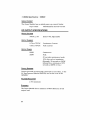
AC INPUT SPECIFICATIONS ........................................................................ 21
Input Voltage ............................................................................................ 21
Input Filter ................................................................................................ 21
Inrush Current .......................................................................................... 22
DC OUTPUT SPECIFICATIONS .................................................................... 22
Output Voltage ......................................................................................... 22
Output Current ......................................................................................... 22
Output Power ........................................................................................... 22
Output Grounds ........................................................................................ 22
Voltage Regulation ................................................................................... 22
Efficiency ................................................................................................... 22
II
OEM300· Preface
Over-Temperature Protection .................................................................. 23
Power Dump .................. "......................................................................... 23
Short Circuit Protection ............................................................................. 23
Overvoltage Protection ............................................................................. 23
OPERATING TEMPERATURES .................................................................... 24
Maximum Ambient: Still Air ...................................................................... 24
Maximum Ambient: Moving Air ................................................................ 24
Maximum Heatplate Temperature ........................................................... 24
Minimum Ambient Tempmature ............................................................... 24
® Protective Circuits in the OEM300 .......................... 25
SHORT CIRCUIT PROTECTION ................................................................... 25
OVER-TEMPERATURE PROTECTION ......................................................... 27
Trip Temperature ..................................................................................... 27
Hysteresis ................................................................................................. 27
POWER DUMP ................................................................................................ 28
OVERVOLTAGE PROTECTION .................................................................... 31
@ Heat & Thermal Management Issues ...................... 33
HEAT MUST BE REMOVED FROM THE OEM300 ....................................... 33
HEATPLATE COOLING .................................................................................. 33
Heatplate Temperature lIimit ................................................................... 34
Heatsink Calculations .............................................................................. 35
Heatsink Problems ................................................................................... 35
CONVECTION COOLING ............................................................................... 36
Ambient Air Temperature Limits .............................................................. 37
Providing Additional Ventilation ............................................................... 37
OVER-TEMPERATURE PROTECTION ......................................................... 38
® Calculating How Many Drives & Motors The
OEM300 Can Operate .............................................. 39
GENERAL GUIDELINES - STEP MOTOR SYSTEMS .................................. 39
WORST-CASE METHOD ............................................................................... 40
CALCULATION METHOD .............................................................................. 41
Where Power is Used in a Motion Control System .................................. 41
Power Requirements During a Typical Move ........................................... 45
Calculating the Power Required .............................................................. 47
A Design Example ................................................................................... 48
Unusual Power Requirements ................................................................. 52
MEASUREMENT METHOD ............................................................................ 53
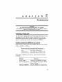
(j) Troubleshooting ........................................................ 57
POSSIBLE PROBLEMS ................................................................................. 57
RETURNING THE OEM300 TO COMPUMOTOR .......................................... 59
INDEX ................................................................................................ 61
1/1
p
R E F A
c
E
MAYBE YOU SHOULDN'T READ THIS MANUAL!
Perhaps you are wondering, "How hard can it be to operate this
Power Module? Why do I need a manual? Can't I just hook up
AC power, plug in some output cables, and power up my system?"
You may be right! If you have experience designing motion
control systems, then perhaps the only information you need
can be found in Chapter (2:1 Installation & Operation. You may
already know how to cool power supplies. You will have calculated the power your system requires, and you will connect the
right number of drives to the Power Module. You will know
about the hazards of load regeneration, and improper equipment grounding. And, you will probably take the proper steps to
ensure electrical noise is not a problem in your system. So, if
you are confident in your preparations, go ahead and plug
away! And best of luck with the OEM300!
The rest of the information in this manual gives details about
the issues mentioned above. Special benefits of using the
OEM300 are also discussed, such as the protective circuits that
guard equipment from damage by short circuits, load regeneration, or high temperatures. A troubleshooting section will help
you locate problems. So, browse through the manual; you might
find other topics of interest, too!
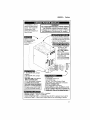
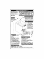
FOR THOSE WHO NEVER READ MANUALS
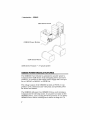
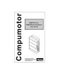
At least look at the next illustration. We have attempted to put
all the critical information you need in this drawing. It is also
shown on the back cover. Use it for quick reference. Consult
the rest of the manual for detailed information.
IV
OEM300 • Preface
OEM300 POWER MODULE
The OEM300 is NOT a
general purpose power
supply. Use it only with
Compumotor OEM
Series Microstepping or
Servo Drives.
WARNING
NO USER SERVICEABLE PARTS INSIDE
The OEM300 contains potentially lethal
Voltages! Do not attempt to repair it. Return
the OEM300 to Compumotor for repairs.
) \.
:(1
m#fNj#j@3 ---... .
Attach Power
Module's heatplate
to a heatsink or
heat sinking
surface
\>~\;
~
..
{;;/[
,J
HEATPLATE COOLING
You must provide a Thermal
;;
Interface to cool the heatplate
I
• Use silicone thermal joint com:
pound or thermal gasket
i · Maximum Temp 60°C (140°F)
;~;?f
I
AMBIENT AIR COOLING
~(qi<'.1~I<i
I
"~I,J'
:
~
"".~PI
if2r 01El~/"
o Keep 2" clearance
around top, bottom, and sides
AIR TEMP LIMITS:
o STILL AIR:
3SoC (9S0F)@200W
40°C(1 04°F)@170W
o MOVING AIR
4S0C( 113°F) @200W
SO°C( 122°F) @170W
,~IiI.~,-,~,.
I
INPUT POWER
----
• 90-132VAC with Jumper
Installed
o 180-26SVAC with Jumper
Removed
o DO NOT USE 132-180VAC
INPUT CONNECTOR:
oS Pin Removable Connector
016 AWG Recommended
You must connect the EARTH
terminal to EARTH GROUND!
(Chassis, cover, EARTH, GND
pins are connected internally)
"/,,, ...r*
JUMPER'
AC
AC
EARTH
OUTPUT POWER
o 7SVDC ±S%
o 2.7A/200W Continuous
o 4.0A/300W Peak
(30 sec., 10% Duty Cycle at Peak)
o Two 7SVDC pins, internally connected
OUTPUT CONNECTOR:
o 6 Pin Removable Connector
o Use16 AWG if < 10 ft., 14 AWG if> 10 ft.
DO NOT CONNECT MUL TlPLE OEM300s IN
PARALLEL! The will not share the load.
PROTECTIVE CIRCUITS
•
•
•
•
SHORT CIRCUIT PROTECTION - Latched
POWER DUMP - Turns 011 at 8SVDC
OVER-TEMPERATURE - Unit shuts down @ 60°C; Latched; Cool to 30°C
OVERVOLTAGE - Shuts down output after O.S sec overvoltage; Latched
v
Preface • OEM300
WARNINGS
& CAUTIONS
Warning and caution notes alert you to problems that may
occur if you do not follow the instructions correctly. Situations
that may cause bodily injury are presented as warnings.
WARNING
NO USER SERVICEABLE PARTS INSIDE THE OEM300!
The OEM300 contains potentially lethal voltages. Do not attempt to repair it.
Return it to Compumotor for any repairs.
Situations that may cause system damage are presented as
cautions.
CAUTION
Do not use AC input voltage in the range of 132-180VAC. AC voltage in this
range can cause excessive voltages to be generated within the OEM300, and
may damage the unit.
VI
c
H
A
p
T
E
R
CD
Introduction
DESIGN INTENTIONS
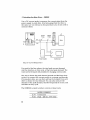
COMPUMOTOR'S OEM SERIES:
A
FAMILY OF MOTION CONTROL PROD-
UCTS
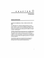
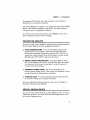
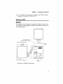
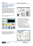
The OEM Series is a collection of high performance motion
control modules. The product line consists of stepper and servo
drives, indexers, motors, and the OEM300 Power Module. The
products are intended to be used as embedded systems around
which the Original Equipment Manufacturer (OEM) can design
a motion control system .
THE ORIGINAL EaUIPMENT MANUFACTURER DECIDES
How TO USE OEM
PRODUCTS
The products have a basic set of features that the OEM can
configure to meet varied needs. The products are not shipped as
ready-to-use units. Compumotor assumes that the OEM system
designer will make design and engineering decisions to properly
use the equipment.
THIS MANUAL PROVIDES INFORMATION NECESSARY TO
MAKE ENGINEERING AND DESIGN DECISIONS ABOUT
PROPER USE OF THE OEM300 POWER MODULE.
1
(j) Introduction • OEM300
OEM Series Drives
OEM300 Power Module
~
.
.!:; ( ",.
:,' i~
-
-
-' ~_
I
:,
','
OEM Series Motors
OEM Series Products -
t-
'-,j',
II
"
_~'
I
,'II
I
'0',:,
'_/
A Typical System
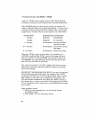
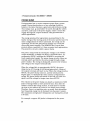
OEM300 POWER MODULE FEATURES
The OEM300 Power Module is optimized to provide power to
Compumotor's OEM Series of microstepping drives and servo
products. It contains a dual range power supply that can operate at 120VAC or 240VAC" at 50/60 Hz.
The voltage output of the OEM300 is fixed at 75VDC. It can
produce 2.7A continuous and 4.0A peak, and provides power
for drives and motors.
The OEM300 will power two OEM650 Drives, each running a
Compumotor 83-135 step motor. It can power as many as five
OEM650 Drives, each running 57-40 step motors. It can power
OEM670 Servo Drives running servo motors as large as 1/2
2
OEM300 • (J) Introduction
horsepower (373 watts). The total number of servo drives is
limited by the total power demand.
The Power Module is compact. It occupies the space of two OEM
drives, and mounts similarly to the drives. Its small footprint
conserves space in equipment cabinets.
To remove excess heat from within, the OEM300 uses a heatplate technique and convection cooling.
PROTECTIVE CIRCUITS
Several circuits in the OEM300 automatically provide protection
for the Power Module and the equipment it powers.
o
OVER-TEMPERATURE The Power Module monitors the
temperature of its heatplate, and will automatically shut
down if the heatplate temperature exceeds 60°C (l40°F). To
restart the Power Module: turn off AC power, cool the Power
Module below 30°C (86°F), and cycle AC power.
o
SHORT CIRCUIT PROTECTION The Power Module monitors current going to the drive, and will shut down its output
if it detects a short circuit in the drive. Cycle AC power to
resume normal operations.
o
INTERNAL POWER DUMP The Power Module has an
internal power dump circuit. This circuit can dissipate excess
energy during load regeneration conditions.
o
OVERVOLTAGE The Power Module will shut down if there
is excessive voltage at its output terminals.
For more information about these circuits, refer to Chapter @
Protective Circuits in the OEM300.
SPECIAL DESIGN ISSUES
You can use the Power Module in many different ways. To use it
effectively, however, you must solve several design issues. Two
of the most important are:
3
CD Introduction • OEM300
COOLING THE OEM300 POWER MODULE
The OEM300 Power Module dissipates some power as internal
heat. This excess heat must be removed from the Power Module.
When you design your system, keep in mind three things you
can do to remove heat.
o
COOL THE HEATPLATE-Make sure heat can pass through
the Power Module's heatplate and into a suitable heat sinking surface.
o
PROVIDE SPACE AROUND THE POWER MODULE-Allow
convection to transfer heat to the ambient air.
o
KEEP AMBIENT AIR WITHIN ITS TEMPERATURE LIMITS-Otherwise, it will not adequately cool the Power Module.
For more information about cooling the Power Module, refer to
Chapter ® Heat & Thennal~ Management Issues.
How MANY
DRIVES CAN THE OEM300 OPERATE?
The OEM300 can deliver power to many different combinations
of OEM Series products. You can save money if you analyze
your system, determine how much power each drive needs, and
then connect the right number of drives to use the full power
capability of the OEM300.
For information on calculating power required by different
motors and drives, see Chapter ® Calculating How Many Drives
& Motors The OEM300 Can Operate.
4
c
H
A
p
T E R
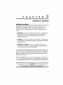
Installation & Operation
BEFORE YOU BEGIN
This chapter tells you how to test, install, and operate your
OEM300 Power Module. Before you begin installation, we
assume you have addressed and solved the following design
issues.
o
HEATSINK You have chosen a heatsink, or a suitable heat
sinking surface. You have selected a way to make good
thermal contact between the heatsink and the Power
Module's heatplate.
::J COOLING You have decided on a method for ventilating the
Power Module, and keeping ambient air temperatures within
specified limits.
o
NUMBER OF DRIVES You have calculated the power required by your system, and have decided how many drives
you can connect to each Power Module.
If you need more information about heatsinks and cooling, refer
to Chapter @ Heat & Thennal Management Issues. For information on how many drives you can connect to the Power Module,
refer to Chapter ® Calculating How Many Drives & Motors the
OEM300 Can Operate.
NOTE: The OEM300 is not a general-purpose power supply, nor
is it a laboratory bench supply. It was designed specifically for
use with OEM Series drives-it is unsuitable for other purposes.
CAUTION
The OEM300 Power Module should only be used with OEM Series drives.
Do not connect it to any other products or equipment.
5
@ Installation & Operation • OEM300
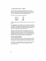
OEM300 SHIP KIT
Inspect the OEM300 upon receipt for obvious damage to its
shipping container. Report any damage to the shipping company. Parker Compumotor cannot be held responsible for
damage incurred in shipment. You should receive one or more
OEM300 Power Modules, depending upon what you ordered.
Compare your order with the units shipped.
Component
OEM300 Power Module
5 Pin Connector
6 Pin Connector
Part Number
OEM300
43-014298-01
43-006606-01
Accessories
OEM300 User Guide
88-013513-01
User guides are not sent with each product. They are available
upon request. Please order user gUides as needed.
BENCH TEST
OEM300 Power Modules are tested at the factory before they are
shipped. Ordinarily, there is no need to perform a bench test on
the Power Module before you install it in your system. If you
want to test the Power Module, you can perform the tests listed
below.
CAUTION
If you operate the OEM300 without adequate cooling, it may be damaged.
Mount the OEM300 to a heats ink. Make sure there is good thermal contact
between the Power Module's heatplate and the heatsink. Do not block the
openings in the cover. Allow adequate air movement so that convection can
cool the Power Module. Remove AC power to the Power Module when you
complete your tests.
To test a Power Module:
1. Connect AC power to the OEM300 (l20VAC with jumper
installed; or 220VAC with jumper removed).
2. LED: the green LED should be illuminated. This indicates
that the 75VDC power supply in the Power Module is operating correctly.
6
OEM300 • (2) Installation & Operation
3. Use a voltmeter to measure the voltage at the 75VDC output
terminals. It should be 75VDC ± 5%.
INSTALLATION
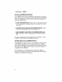
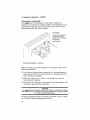
MOUNTING
The OEM300 Power Module is designed to minimize panel area,
or footprint, in an equipment cabinet. Dimensions are shown in
the drawing below.
4x 00.187 (4.75) Thru
(Clearance for #8 PHP Screw)
Dimensions in inches (millimeters)
0.813
(20.6)
~
Y,&".·44
LhvJi~~raELh
II ,
0.102 (2.6)
..~__________~5.~00~(1~27~)____
J
I,
2.000
(50.8)
,I
Dimensions-OEM300 Power Module
7
@ Installation & Operation • OEM300
Panel Layout and Minimum Spacing
Do not obstruct the openings in the top and bottom of the
OEM300. Provide space for air circulation between the Power
Module and other equipment. The figure below shows the
minimum spacing required.
[---1-------------1 2 (50.8) Clearance
:
(Minimum)
:
.~
~ I==========l
2.375
-1
(60.3)
2 (50.8)
Typ .......,
r--
I=±::======}----.,-
1
1
1
1
1
1_ 2 __
't%'t®i~' ,J
-
: (50.8)","''''''(;'
1Clearance
:::
:(Minimum) ,,,,,~:i;~,,,
I
I
T
: 2 (50.8) Clearance
I
(Minimum)
4.65
(118)
~: ::'.,,'
: I
i:-'' '
.,,. ~ I __
~~4(101)~
Minimum
~ - - - t . ,. . . ., , , , , . . . . ,...-=~---. ,.....,.__...... r..,..",,~
T
2
2.35
(50.8) (59.7)
rl'G"+=l=..J..=--...i--
4.65
(118)
Dimensions in inches
(millimeters)
Panel Layout-OEM300 Power Modules with OEM Series Drives
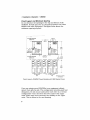
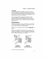
If you are using several OEM300s in an eqUipment cabinet,
mount them side by side. This configuration provides good heat
dissipation. Do not mount units above each other in a vertical
configuration-heat rises from the lower units to the upper
units, which may cause excessive heat buildup in the upper
units. This is shown in the next drawing.
8
OEM300 • (2) Installation & Operation
/
"I
\
I
I
\ I
I \
I
/
\
\
"\
I
\ I
I \
I
\
/
- m':
\
I
I
\
I
/
I
I
I \
I
I
I
\ \ I
\ I I I I'
/
I I II / I I (
\
I
\
\
I
I
I
\
\
I
\
\
/
\
\
/
'£'-0
:'".--:00 rn~···....
I
\
I
- m':
,/
i,-.
::00
_", ~=i:· . ·
_",,~U;2' $
/
I
I
I
I
(
\
/
\
I
I
,/
I
'
~
__"U:>=e ._
_
Mount Power Modules Side by Side ....
.... Not One Above the Other
Side by Side Mounting is Preferred
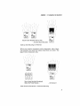
When you position equipment and components. place those
that produce the most heat above those that are cooler. The
figure below illustrates this.
\
/
\
\
/
\
I
\
I
"
"
/
(
I
I
- ........
I
I
I
I
J
J
I
I
J
\
(
\
I
\
\
I
\
\
I
/
/
\
\
I
J
I
(
I
J
\
\
\
I
I
/
/
Mount Heat SensitivE3 Equipment
Below the Power Module ....
.... Not Above It
Heat Sensitive Equipment-Preferred Mounting
9
(2) Installation & Operation • OEM300
Attachment to Heatsink
You must attach the heatplate of the Power Module to a
heatsink or suitable heat sinking surface. The heatplate is the
pathway through which you can remove much of the excess
heat generated by the Power Module.
HEATSINK
Use silicone thermal joint
compound or thermal
gasket between heatplate
and heatsink.
HEATPLATE
Attaching Heatplate to Heatsink
When you attach the Power Module to a heatsink, observe the
following gUidelines:
o
o
o
Use silicone thermal joint compound or a thermal gasket to
ensure good thermal contact between the heatsink and the
Power Module's heatplate.
Make sure there are no voids or air pockets between the
heats ink and heatplate.
VerifY that the heatsink is not warped (a warped surface will
not make a good thermal interface).
CAUTION
You must attach the heatplate of the Power Module to a heatsink or suitable
heat sinking surface. Use silicone thermal joint compound or a thermal gasket
to provide a good thermal interface.
For more information about choosing a heatsink, refer to Chapter @ Heat & Thermal Management Issues.
10
OEM300 • (2) Installation & Operation
Ventilation
The OEM300 depends on ventilation to remove much of its
excess heat. Mount the Power Module so that air can circulate
around it. Follow the gUidelines for minimum spacing that were
shown earlier in this section. Make sure the openings in the top
and bottom of the cover are not blocked.
If you have high ambient temperature conditions. or heatproducing equipment near the OEM300. you may need to
provide a fan for air circulation and cooling. For more information about ventilation. refer to Chapter @ Heat & Thermal Management Issues.
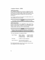
AC POWER CONNECTION
Use AC input power in the range of 90-132VAC or 180-265VAC
to operate the OEM300. and configure the jumper wire on the
power connector to match your input voltage.
Voltage in the intermediate range (l32-180VAC) MUST NOT BE
USED!
There are two terminals on the 5-pin AC input connector that
require the installation or removal of a jumper wire. depending
upon the input voltage you use. The following illustration shows
how to configure the jumper for your voltage.
120VAC:
Install jumper
240VAC:
Remove Jumper
AC Input Connector-Jumper Configurations
11
(2)
Installation & Operation • OEM300
120VAC Operations
The OEM300 is shipped from the factory configured for input
voltage in the 90-132VAC range, with the jumper in place on
the connector. Leave the jumper in place if you operate in this
range. Operating without a jumper will cause poor system
performance.
Line voltage is present on the jumper. For safety reasons, use
only insulated wire for the jumper.
WARNING
High voltage is present on the jumper. Use insulated wire for safety.
240VAC Operations
If you use input power in the 180-265VAC range, remove the
jumper. Do not operate the OEM300 in the 180-265VAC range
with the jumper in place. Doing so can produce high internal
voltages which could cause severe system damage.
CAUTION
Do not use a jumper when using AC input voltage in the 180-265VAC range.
If a jumper is in place, input voltage in this range will cause the OEM300 to
generate high internal voltages which could result in system damage.
AC input information is summarized below:
Input Voltage:
90VAC-132VAC
180VAC-265VAC
Forbidden Range:
Jumper installed
Jumper removed
132VAC-180VAC
Wire Size:
16 AWG (1.5 mm2 ) minimum
Input Connector:
5-pin removable connector
(Phoenix PIN GMVSTBR 2.5/5-ST)
The following illustration shows the AC input connector properly configured for both voltage ranges.
12
OEM300 • (2) Installation & Operation
240VAC
120VAC
JUMPER
AC
LINE
AC
NEUTRAL
EARTH
()
01
i
0i
0:
0:
AC
LINE 1
AC
LINE 2
EARTH
0
0
0
0
0
EARTH
GROUND
EARTH
GROUND
Note:
Note:
Line and Neutral
are Interchangeable
Line 1 and Line 2
are Interchangeable
AC Input Connections
CAUTION
Do not use AC input voltage in the range of 132-180VAC. AC voltage in this
range can cause excessive voltages to be generated within the OEM300, and
may damage the unit.
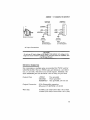
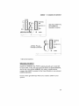
DC OUTPUT CONNECTION
For convenience, multiple pins are provided for 75VDC and for
GROUND (GND). The two 75VDC pins are identical-use either
one. or use both. whichever your needs require. Similarly. the
three GROUND pins are identical-use as many as you need.
Output Pins:
+ 75VDC
GROUND
RESERVED
Output Connector:
6-Pin Removable connector
(Phoenix PjN MVSTBR 1.5j6-ST)
Wire Size:
AWG (1.5 mm2) ifless than 10 ft. (3m)
14 AWG (2.5 mm2) if more than 10 ft. (3m)
Two provided
Three provided
One provided; Do not use
16;
13
@ Installation & Operation • OEM300
The following drawing illustrates typical power cabling for
various OEM Series drives.
AC
POWER=~~U lUt:::t::;=:::t:~'
MICROSTEPPING
SERVO
OEM Series Drive
OEM Series Drive
@~I
POWER
FAULT
REMOTE
e
0
0
....
VOC· _
A.
®
A·
POWER
0
REF
CURRENT
DUMP
VDC+ _
"-----
0
0
0
',..
0
•
•
Power Connections to Various Drives
OUTPUT POWER CABLE LENGTH
Make the output power cables as short as possible. Voltage
drops occur in cables over 3 feet long. and cause a reduction in
power delivered to the drive. To minimize cable length. mount
the OEM300 close to the drive.
The next drawing shows that the 75VDC output pins are connected together internally. It also shows the internal connections of the ground pins and cover.
14
OEM300 • I2J Installation & Operation
(RESERVED)
GND
~+75VDC
~GND
•
@
2.7A
GND Pins, EARTH Pin,
and COVER are
Internally Connected
POWER
(RESERVED)
GND
~+75VDC
+75VDC Pins are
Internally Connected
@
2.7A
~GND
POWER
Internal Connections
GROUNDING FOR SAFETY
Inside the OEM300, the 75VDC output grounds are connected
to each other, to the AC input ground (which is labeled EARTH),
and to the cover of the OEM300. For safety considerations,
connect the EARTH terminal of the Power Module to an external
EARTH GROUND.
Do not create ground loops when you connect cables to your
system.
15
® Installation & Operation • OEM300
How MANY
DRIVES CAN BE CONNECTED TO ONE OEM300?
The OEM300 can deliver power to many different combinations
of drives, indexers, and the motors they operate. Determine the
power demanded by your application, and verifY that the
OEM300 will supply the amount of power needed. You may
need multiple OEM300 Power Modules; or, you may be able to
use fewer Power Modules than anticipated. For details on how
to calculate the power output required of the OEM300, refer to
Chapter ® Calculating the Number oj Drives & Motors the
OEM300 Can Operate.
CONNECTING MULTIPLE DRIVES TO THE OEM300
Consult the following figure for gUidelines on how to connect
more than one drive to the OEM300. You can make a single
power bus or you can use the extra pins in the DC output
connector to make a second power bus.
~T
?~~ 1IIIi
-:;; 1J
EARTH
GROUND
Power Cabling Options
16
OEM300 • (2J Installation & Operation
You can connect OEM6!)O Microstepping Drives and OEM670
Servo Drives to the same OEM300 Power Module.
USING MORE THAN ONE OEM300 POWER MODULE
The OEM300 is not designed for current sharing. Each unit is
designed as a standalone Power Module. Do not attempt to
connect multiple OEM300s together in parallel. Instead, connect drives directly to individual Power Modules.
CAUTION
Do not connect multiple OEM300 Power Modules in parallel. Connect drives
directly to individual Power Modules.
ELECTRICAL NOISE CONTROL
The OEM300 Power Module contains a switching power supply.
Internally, it rapidly switches several high voltage components
on and off. This rapid switching creates electrical noise, which
is a standard characteristic of switching power supplies.
You may need to reduce electrical noise, depending on your
application and the sensitivity of the equipment in your system.
The following information is provided to help with your noise
reduction efforts. For additional information about controlling
electrical noise, consult the technical reference section in
Compumotor's catalog.
Switching Frequencies
Primary Switching Frequency:
118 kHz ± 9 kHz
AC Line Switching Frequency:
48-72 Hz, plus harmonics
(AC line frequency valies by country)
Input Filter
Internally, the OEM300 has an AC input filter. This filter reduces the electrical noise that is conducted from the Power
Module to the AC power line. If you need to further reduce the
noise sent out over the AC lines, you can install an external
filter at the point where AC power is connected to the Power
Module. A variety of filters are commerCially available from
many different vendors.
17
(2) Installation & Operation • OEM300
Output Filter
We recommend that no external filters be placed between the
output of the OEM300 Power Module and any equipment
connected to it.
The OEM300 Power Module should be connected directly to
Compumotor OEM Series drives. It is designed to respond
rapidly to power demands from drives and their loads. Any
external filters, such as EMI filters or extra capacitors, may
seriously impede the response and performance of the Power
Module.
Output Cables
Noise can be coupled from the output cables to sensitive equipment by means of electromagnetic radiation. This type of noise
problem is known as Electro Magnetic Inteiference, or EM!.
If you need to reduce EMI emanating from the power cables, use
shielded power cables and properly ground the shield. You can
achieve additional reductions in EMI if you run cables in conduit or steel pipe. Cables should be as short as possible. Keep
cables away from sensitive equipment.
If you run separate wires for power cables (POS and GND,
or + and - ), both wires should be parallel, immediately adjacent
to each other. and twisted together. This will minimize circuit
inductance and radiated noise.
Proper Application of the OEM300
In extreme cases and unusual applications. sensitive equipment
can be highly susceptible to electrical noise problems. In situations like this. a switching power supply might be the wrong
type of power supply to use.
If your system cannot tolerate the amount of electrical noise
generated by the OEM300" and noise reduction techniques fail
to reduce noise to tolerable levels, then you may need to consider using a linear power supply. such as the Compumotor
DC 4. Linear supplies are virtually noise free. and give excellent
results in noise-sensitive applications. Unfortunately. in comparison to switching supplies. linear supplies are large. heavy.
and dissipate more power. They also suffer from poor output
regulation. which may affect the high-speed performance of
your system.
18
OEM300 • !2J Installation & Operation
OPERATION
The OEM300 Power Module is intended to be hardwired within
your system. Therefore. it does not have an ON/OFF switch. AC
input cables. or DC output cables. You should provide a means
for turning the OEM300 on and off. connecting input AC power.
and delivering DC output power to your drives.
During operation, a green LED on the front panel is illuminated
to indicate the 75VDC section is functioning.
19
I2J Installation & Operation • OEM300
20
c
H
A
p
T
E R
@
OEM300 Specifications
WARNING
NO USER-SERVICEABLE PARTS INSIDE THE OEM300!
The OEM300 contains potentially lethal voltages. Do not attempt to repair it.
Return it to Compumotor for any repairs.
AC INPUT SPECIFICATIONS
INPUT VOLTAGE
Low Range: ,Jumper installed
High Range: LTumper removed
90VAC to 132VAC
180VAC to 265VAC
Forbidden Range:
132VAC to 180VAC
WARNING
High voltage is present on the jumper. Use insulated wire for safety.
CAUTION
Do not use AC input voltage in the range 132-180VAC.
Voltage in this range can cause excessive voltages to be generated within the
OEM300, and may damage the unit.
INPUT FILTER
The Power Module has a line filter at the AC input that minimizes noise energy sent out to the power line.
21
@ OEM300 Specifications • OEM300
INRUSH CURRENT
The Power Module has an initial power up current limiter.
Input Limit:
40A Maximum Inrush Current
DC OUTPUT SPECIFICATIONS
OUTPUT VOLTAGE
75VDC ± 5%
(Fixed-Not Adjustable)
OUTPUT CURRENT
2.7A at 75VDC
4.0A at 75VDC
Continuous Current
Peak Current
OUTPUT POWER
200W
300W
Continuous
Peak
30 seconds maximum at peak
10% duty cycle at maximum
(Example: 30 seconds at 300W,
followed by a minimum of 270
seconds at 200W or less.)
OUTPUT GROUNDS
Output grounds are internally connected to each other, to the
AC input ground (labeled EARTH), and to the cover of the
OEM300.
VOLTAGE REGULATION
±
5% maximum
EFFICIENCY
The Power Module has a minimum of 80% efficiency at full
output load.
22
OEM300 • @ OEM300 Specifications
OVER-TEMPERATURE PROTECTION
The Power Module will shut down if its heatplate reaches a
temperature of 60°C (l40°F). This is a LATCHED condition. To
resume normal operations, turn off AC power, cool the Power
Module below 30°C (86°F), and then turn on AC power.
POWER DUMP
The OEM300 has a power dump circuit that can dissipate
excess energy from load regeneration conditions.
THRESHOLD VOLTAGE: 85VDC ± 3VDC
ENERGY DISSIPATION:
Consult Power Dump section in Chapter ® Protective
Circuits
AVERAGE POWER DISSIPATION RATE:
PEAK
POWEI~
8 Watts
DISSIPATION RATE:
722.5 Watts
EQUIVALENT ENERGY: Two 83-135 motors, each
turning loads with 10: 1 Rotor Inertia at 50 rps,
Simultaneously decelerate to a full stop in 0.3 sec.
SHORT CIRCUIT PROTECTION
The Power Module shuts down the 75VDC output if there is a
short circuit in output cables or drives. This is a LATCHED
condition. Cycle AC power to resume normal operations.
Short Circuit Current
Response Time
9 Amps
Immediate
(output shuts down)
6 Amps
Responds in 3 seconds
OVERVOLTAGE PROTECTION
The Power Module has an output overvoltage protection circuit.
It shuts down the Power Module if the power dump stays on
continuously for more than one-half second. This is a LATCHED
condition. Correct the problem, then cycle AC power to resume
normal operations.
23
® OEM300 Specifications • OEM300
OPERATING TEMPERATURES
MAXIMUM AMBIENT: STILL AIR
35°e (95°F)
With a 200W Load
40 0 e (104°F)
With a 170W Load
MAXIMUM AMBIENT: MOVING AIR
45°e (113°F)
With a 200W Load
50 0 e (122°F)
With a 170W Load
MAXIMUM HEATPLATE TEMPERATURE
MINIMUM AMBIENT TEMPERATURE
24
c
H
A
p
T
E R
®
Protective Circuits in the OEM300
Extreme conditions can damage power supplies. The OEM300
Power Module contains several circuits that will protect it from
threatening conditions, such as short circuits in drives, excessive heat buildup in equipment cabinets. or energy regenerated
by high inertial loads.
The OEM300's protective circuits are built-in and work automatically. You do not need to do anything to turn them on; in
fact. you cannot alter them in any way. Because they are automatic. they can cause unexpected results if you do not understand how they work.
For example. if there is a short circuit in a drive connected to
the Power Module. the Power Module will shut down. If you are
unaware of the short circuit protection feature. you might think
the shutdown is caused by a defective Power Module and waste
time trying to fix it. If you know about the protective circuitry,
however, you can find the root cause of the problem-the short
circuit in the drive-more qUickly. You can proceed straight to
locating and fixing the short circuit, and getting your system
running again.
The following information about the protective circuits will help
you understand how they work. when they take effect. and the
results they produce. This will aid your troubleshooting efforts.
and help you locate the cause of unexpected behavior.
SHORT CIRCUIT PROTECTION
The OEM300 continuously monitors output current at the
75VDC terminals. If it detects a rapid current rise to excessive
levels. it interprets the current rise as a short circuit fault in the
drive. It shuts off power to the 75VDC output terminals. Inter-
25
@ Protective Circuits in the OEM300 • OEM300
nally. the 75VDC power supply section of the Power Module
continues to function. and the green LED remains illuminated.
If the OEM300 detects a short circuit current in excess of 9
amps. it will shut down the output immediately. It will monitor
a 6 amp current and shut down the output if the current lasts
longer than 3 seconds. This is summarized in the table below:
Current Level
9 amps
6 amps
4-6 amps
2.7-4 amps
0-2.7 amps
Response Time of Protection
Respond:
Immediately
Respond:
In 3 seconds
No Response: Beyond specified
operating range
No Response: Intermittent operating range
No Response: Continuous range
When the 75VDC output is shut down. the shutdown is a
IATCHED condition (the 75VDC output will remain off until
power is cycled). To CYCLE POWER. turn off the AC power to
the OEM300. wait approximately 30 seconds (the green LED
will turn off). then turn on AC power.
The output is latched in the OFF condition for safety reasons.
Short circuit protection guards people from injury and equipment from damage.
IMPORTANT TROUBLESHOOTING NOTE: You may be confused
if your system unexpectedly stops. the voltage at the 75VDC
terminals is 0 Volts. but the LED is illuminated. There is probably a short circuit fault in your equipment. Remember. the
LED will remain illuminated. even when the 75VDC output is
shut down due to a short circuit fault. Find and fix the problem
in your equipment. then cycle power to the OEM300 and restart
your system.
Other possible causes:
CD Excessive load regeneration-see the Power Dump
description below.
@ Overvoltage-see the description below.
26
OEM300 • @) Protective Circuits in the OEM300
OVER-TEMPERATURE PROTECTION
The OEM300 has a circuit that protects it from damage due to
over-temperature conditions. This circuit monitors the temperature of the Power Module's heatplate. A temperature rise above
60°C (140°F) will trigger a thermal switch; when this happens,
the protection circuit shuts down the Power Module, and turns
off the green LED. This is a latched condition. Before the Power
Module can operate again, its heatplate must cool below approximately 30°C (86°F) and AC power must be cycled.
The Power Module will cool faster if you turn off AC power while
it cools. If AC power is on, several bleeder resistors will continue
to dissipate their heat into the heatplate and keep it warm, even
though the Power Module is off. It will cool much faster with the
power off. Therefore, design your system so that, if an overtemperature shutdown occurs, AC power is turned off while the
Power Module cools down.
TRIP TEMPERATURE
DESIGN TIP: Use 60°C (140°F) as the maximum heatplate
temperature allowed for continuous operation of the Power
Module. Because of the manufacturing tolerance on the thermal
switch, different OEM300 units will shut down at different
temperatures in the 60°C to 70°C range (140°F to 158°F). For
predictability, use 60°C fl40°F) as the shutdown temperature.
HYSTERESIS
The thermal switch used by the over-temperature protection
circuit has built-in thermal hysteresis. The switch will open at
65°C ± 5° (14goF ± gOF), and shut down power to the OEM300.
It will not close until it has cooled to apprOximately 30°C (86°F).
This means that the OEM300 will not operate again until it has
had adequate time to cool.
TROUBLESHOOTING NOTE: If the OEM300 shuts down because of excessive heatplate temperature, the heatplate must
cool below 30°C (86°F) before the unit can be restarted. Turn off
AC power while the OEM300 cools.
27
@ Protective Circuits in the OEM300 • OEM300
POWER DUMP
During normal use. a motor consumes power from a power
supply. During deceleration or a free-wheeling shutdown.
however. the motor becomes a generator and produces energy.
This energy must go somewhere! It travels through the cables
and drive. and back to the power supply. where it enters the
supply through the output terminals. This phenomenon is
called regeneration.
The energy produced by regeneration is proportional to the
kinetic energy of the moving parts of the motor and its load. For
some configurations of motors and loads. the energy can be
quite high. and has the potential to damage any connected
drives and power supplies. The OEM300 has a circuit that
protects drives connected to it from excessive load regeneration.
The protective circuit is called a power dump.
The power dump works by sensing the voltage at the 75VDC
output terminals. A voltage rise above a threshold value. approximately 85VDC. indicates the OEM300 is receiving too
much regenerated energy. The power dump circuitry closes an
internal switch and diverts the extra energy through a large
power resistor. The energy is dissipated as heat in the resistor.
and voltage at the output terminals falls.
When the voltage falls to apprOximately 82VDC. the power
dump turns off. If energy is still being regenerated. voltage at
the output terminals will start to rise. When the voltage reaches
85VDC. the power dump turns on. and the whole process
begins again. To dissipate the entire amount of regenerated
energy. the power dump will switch on and off. over and over
again. until the voltage no longer rises above 85VDC.
The resistor in the power dump can absorb a maximum of 400
joules of energy within a short period of time. And. after the
resistor converts the energy to heat. it needs time to transfer
the heat to the ambient air before it can absorb more energy.
Therefore. there is a repetition rate. or period. that determines
how frequently energy can be dumped into the power resistor.
The maximum average power dissipation rate during this period
is 8 watts.
For example. suppose 400 joules is dissipated in the power
28
OEM300 • @ Protective Circuits in the OEM300
dump in one second. How long must we wait before we can
repeat the regeneration event? Average power dissipation must
be 8 watts or less during the total regeneration event (dump on
plus time waiting). We find the repetition rate by dividing 400
joules by 8 watts-this gives us 50 seconds. (Remember, 1 watt
is equal to 1 joule per second. So, 400 joules/8 watts = 50
seconds.) We must wait 49 seconds before regenerating again (1
second ON plus 49 seconds OFF = 50 seconds).
Another factor to consider in power dump performance is the
peak power dissipation rate-722.5 watts. If your system sends
power to the power dump at a rate higher than 722.5 watts, the
power dump cannot dissipate the power fast enough to lower
the voltage at the output terminals. It will stay on continuously.
Mter one-half second, the overvoltage circuit will shut down the
output of the OEM300. (See the next section for an explanation
of the overvoltage protection circuit.)
For example, suppose a moving system of motors contains 200
joules that must be dissipated in the power dump. How quickly
can it decelerate without overwhelming the power dump? If
energy is dissipated at the peak rate of 722.5 watts, we find that
the deceleration time is 200 joules/722.5 watts, or 0.3 seconds.
The repetition rate will be 200 joules/8 watts, or 25 seconds.
Power dump information is summarized below.
THRESHOLD VOLTAGE:
On
= 85 VDC
Off
=
82 VDC
29
@ Protective Circuits in the OEM300 • OEM300
The numbers in the table show the energy that can safely be
absorbed in the OEM300's power dump. When a motor regenerates energy. much of the energy is dissipated as heat in the
motor and drive. Therefore. total energy contained in the moving parts of the motor and load can be higher than the numbers
shown in the table. After motor and drive losses. the energy left
over will be sent into the power dump-this is the energy that is
listed in the table above.
(For a discussion of motor and drive losses. see the section
Where Power is Used in a Motion Control System. in Chapter ®
Calculating How Many Drives & Motors the OEM300 Can Operate.)
The power dump in the OI~M300 is designed to dissipate as
much regenerated energy as would occur in a worst-case situation where two 83-135 motors each operate loads with 10: 1
rotor inertia. Under these conditions. when regeneration occurs.
the power dump will turn on and dissipate the excess energy.
EXAMPLE: A single OEM83-135-MO motor turns a load that
has ten times the motor's rotor inertia. Speed of the system is
50 rps. The kinetic energy in the moving parts of the system can
be calculated as follows:
Kinetic Energy = (1/2) J
(if
= (1/2) HI + 10)(1.87 kg·cm2)(10-4 )} (21t·50)2
= 101.5joules
Where:
J = inertia. in kg·cm 2
1.87 kg·cm 2 is the motor's rotor inertia. It can
be found in the OEM650 User Guide.
10-4 is a conversion factor. to convert from
kg·cm 2 to kg·m 2 • units which are compatible
with joules.
m
= velocity. in radians/sec
(m
= 21t·rps)
Kinetic energy in this system is 101.5 joules. Kinetic energy in a
similar system with two motors would be approximately 200
joules. which can be absorbed in 0.3 sec.
(200J/722.5W"" 0.3 sec. See previous page.)
30
OEM300 • @ Protective Circuits jn the OEM300
Compumotor's OEM650 Microstepping Drive also has a power
dump circuit. To use it. you must connect an external power
resistor to the drive. However. the threshold voltage for the
power dump in the OEM300 is much lower than the threshold
in the OEM650. The OEM300's power dump will always tum on
first. Therefore. there is usually no need to use the power dump
in the drive. as long as your system's stored energy can be
safely dissipated in the OEM300's power dump.
However. if you design a system that has enough stored energy
to overwhelm the power dump in the OEM300. you may want to
use the drive's power dump to protect the drive. Regenerating
this much energy should be avoided. however. It is beyond the
speCified energy dissipation limits. and can damage the
OEM300.
OVERVOLTAGE PROTECTION
An overvoltage protection circuit guards your drives and equipment from excessively high voltages produced by a damaged
OEM300. It also protects your system from excessive regeneration.
If a damaged element within the Power Module causes it to
produce an output voltage in excess of 85VDC. the power dump
threshold voltage is exceeded. and the power dump turns on.
The overvoltage circuit monitors the power dump. If the power
dump stays on for more than one-half second. the overvoltage
circuit will shut down the output terminals.
The overvoltage circuit also monitors the power dump when
load regeneration occurs. In this case. if the power dump stays
on longer than one-half second. excessive regeneration is
occurring. To protect the OEM300. the overvoltage circuit will
shut down the output terminals.
TROUBLESHOOTING NOTE: There are no separate indicators
to distinguish between an excessive regeneration fault. a damaged Power Module. or a short circuit fault. Any of these conditions will shut down your system: and. the green LED will
remain illuminated.
31
@ Protective Circuits in the OEM300 • OEM300
When you attempt to restart your equipment, you should be
able to isolate the cause. If the problem is due to a short circuit
fault in connected equipment, the Power Module will shut down
instantly when it is turned on. If the problem is due to a damaged Power Module, it wil1 run for 1/2 second and shut down,
even with no load regeneration. If the problem is due to excessive regeneration, the Power Module will power your system
until load regeneration occurs; then it will shut down. These
conditions are summarized below.
Power Module Shuts Down ....
... .instantly when turned on
.... after running 1/2 second
.... when regeneration occurs
32
Probable Cause
Short circuit fault in drive
Damaged OEM300
Excessive regeneration
c
H A
p
T
E R
@
Heat & Thermal Management Issues
HEAT MUST BE REMOVED FROM THE OEM300
The OEM300 will operate over a broad range of ambient temperatures. As it delivers power to connected equipment, it also
produces heat internally. During load conditions where the
OEM300 is supplying its maximum output power, internally
generated heat can be as much as 35 watts. In the small space
enclosed by the Power Module, 35 watts is a significant amount
of heat! To keep the Power Module within its operating temperature limits. you must use two methods to remove this heat:
heatplate cooling and convection cooling.
HEATPLATE COOLING
The OEM300 uses a HEATPLATE technique to provide a heat
dissipation path. The heatplate is the entire back surface of the
OEM300; it is the unpainted metal plate you see when you look
at the back of the Power Module.
Internally. many of the components that produce the most heat
are thermally bonded to the heatplate. The heat they produce
can be removed through the heatplate pathway. This means
that if you can cool the heatplate, these components will stay
cool, too.
To cool the heatplate, you must mount it to a thermal mass,
such as a heatsink or a heat sinking surface. Make sure that
the surface of the heatsink is clean and flat (not warped). There
should be good contact between the heatplate and heatsink,
with no voids or empty spaces between them. Use silicone
thermal joint compound or a thermal gasket to ensure good
heat transfer across the thermal interface.
33
@ Heat & Thermal Management Issues • OEM300
CAUTION
The heatplate must be mounted to a heatsink or proper heat sinking surface.
Ensure good contact between the heatplate and the mounting surface. Use
silicone thermal joint compound or a thermal gasket to ensure heat transfer
from the heatplate to the mounting surface.
HEATPLATE TEMPERATURE LIMIT
Maximum Heatplate Temperature:
60°C (140°F)
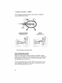
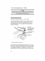
To check the heatplate temperature in your system, take measurements after the system has run long enough to reach
steady temperatures. As the next drawing shows, place your
thermal probe directly on the heatplate, not the heatsink to
which it is attached.
For accurate temperature
measurements, do not
place thermal probe on
heatsink. Instead ....
.... position thermal probe
on the heatplate.
Measuring Heatplate Temperature
Do not assume that the heatplate and heatsink are at the same
temperature. If the thermal interface between them is not good,
heat may not transfer from the heatplate to the heatsink. If heat
is not leaving the heatplate, its temperature can become very
high, while just a few inches away the heatsink is much cooler.
34
OEM300 • @ Heat & Thermal Management Issues
In this situation, if you place a thermal probe on the heatsink,
you might read an acceptable temperature. This could lead you
to think your system is within limits, but it is not. Therefore,
make sure you place the probe on the heatplate. This will give
you the most accurate temperature information about your
system.
HEATSINK CALCULATIONS
To cool the heatplate of the OEM300, mount the Power Module
to a heatsink. Or, you may prefer to mount the Power Module
directly to a heat sinking surface, such as the metal wall of an
equipment cabinet.
Your heats ink or heat sinking surface should satisfY this equation:
where:
TA
is the ambient temperature
Rth~A
is your heatsink's thermal resistance to ambient
conditions, in °CjW
20W in this equation is the amount of heat the Power Module
will dissipate through its heatplate, when it operates at its
maximum continuous output power. This is a worst-case
condition. If your application uses less power, the Power Module
will dissipate less heat. In this case, you can use a number
smaller than 20W in the equation above.
HEATSINK PROBLEMS
Several problems with heatsinks can cause poor heat transfer.
Warped Heatsink
Many heatsinks are made from aluminum extrusions. During
the extrusion process, the aluminum is hot. When it cools, it
sometimes warps. A warped heats ink will not make good contact with the Power Module. Heat transfer may be inadequate.
Ensure that your heatsink is flat.
35
® Heat & Thermal Management Issues • OEM300
Voids in Thennal Interface
The heatsink should be in full contact with the Power Module's
heatplate. Use silicone thermal joint compound or a thermal
gasket to ensure full contact. Make sure that there are no air
pockets, empty spaces, or voids in the thermal grease. Voids
can severely reduce the amount of surface area available for
heat transfer.
Paint
Paint on a heat sinking surface can cause poor thermal transfer. If you attach the Power Module to the wall of an equipment
cabinet, make sure that any paint has been removed from the
area where the Power Module attaches to the wall.
Thennal Contact Only Around Fasteners
Flexible or non-rigid heat sinking surfaces, such as equipment
cabinet walls, are prone to a particular problem. The pressure
of the bolts or screws that attach the Power Module to the wall
can cause the wall to warp slightly. There may be thermal
contact in the circular area immediately surrounding the bolt,
but nowhere else. If you use the wall of an equipment cabinet
for a heat sinking surface, make sure there is good thermal
contact everywhere between the heatplate and your surface, not
just around the bolts.
CONVECTION COOLING
Several heat produCing components inside the OEM300 are not
attached to the heatplate. They must dissipate their heat to the
surrounding air. The open top and bottom of the OEM300 allow
air to circulate and carry heat away from these components.
If the openings are blocked, air cannot circulate through the
Power Module. Heated air is not replaced by cooler air; instead,
the air is motionless, and heat builds up around the hot components.
Mount the OEM300 properly to ensure adequate air Circulation,
and to keep temperatures within acceptable limits. Refer to
Chapter@ Installation & Operation for information on recommended mounting patterns, spacing between the Power Module
and adjacent equipment, and other issues. Make sure the open
top and bottom of the OEM300 are not obstructed.
36
OEM300 • @ Heat & Thermal Management Issues
CAUTION
Do not obstruct the openings in the top and bottom of the OEM300. Ensure
adequate space for air circulation between the OEM300 and other equipment.
AMBIENT AIR TEMPERATURE LIMITS
The ambient air temperature must remain below these limits to
adequately cool internal components:
STILL
A.IR:
35°e (95°F) with a 200W load
40 e (104°F) with a 170W load
0
MOVING AIR:
45°e (113°F) with a 200W load
50 0 e (l22°F) with a 170W load
To measure ambient air temperature. position your thermal
probe below the OEM300. approximately one inch away from it.
Make measurements after your system has run long enough to
reach a stable operating temperature.
PROVIDING ADDITIONAL VENTILATION
If you have heat-producing equipment near the OEM300. you
may need to provide additional ventilation to keep the ambient
air temperature within limits. Additional ventilation can be
provided by vent holes in the equipment cabinet. a fan to move
air in the cabinet. a combination of fans and ventilation ducts.
or some other method.
Simply by moving air past the OEM300. you can raise the
maximum ambient temperature limit by looe (l8°F). from 35°e
to 45°e for a 200 watt load. or from 40 0 e to 50 0 e for a 170 watt
load. (95°F to 113°F at 200W. or 104°F to 122°F at 170W.)
You may wish to include a fan in your system. to take advantage of this extended temperature range. The fan should be
rated at approximately 20 cfm (cubic feet/minute) or more. It
should be 5 to 10 inches away from the OEM300. and positioned so that it blows air from the bottom up through the
OEM300.
37
® Heat & Thermal Management Issues • OEM300
EXAMPLE: Suppose you want to power a 170 watt system with
an OEM300. and you need to place your equipment in a sealed
equipment cabinet. You mount the Power Module in a cabinet
that has no fan or ventilation holes. Mter you power up your
system and let it run long enough to reach stable temperatures.
you check the temperature in the still air near the OEM300.
You find it is 45°C (l13°F), which is higher than the 40°C
(l04°F) recommended limit for still air.
So. you install a fan in the cabinet. and verify that it circulates
air through the Power Module. Once again you measure the air
temperature near the OEM300. and find that it is still 45°C
(l13°F). But. because the air is moving. the ambient air temperature is now within recommended limits. You can still use a
sealed cabinet without ventilation holes!
OVER-TEMPERATURE PROTECTION
The OEM300 has a circuit that protects the Power Module from
damage due to over-temperature conditions. This circuit shuts
down the Power Module if the heatplate temperature rises above
60°C (140°F).
For more information about the over-temperature circuit. refer
to Chapter ® Protective Circuits in the OEM300.
38
c
H
A
p
T
E
R
®
Calculating How Many Drives & Motors The OEM300 Can Operate
You can use the OEM300 Power Module to power
Compumotor's OEM Series servo motor drives (OEM670T.
OEM670X. OEM670SD. etc.) and OEM Series step motor drives
(OEM650. OEM650X. OEM350. OEM350X. etc.). This chapter
will explain how to determine the number of step motor drives
you can connect to the OEM300.
For a similar discussion about servo motor drives. see
Chapter ® Power Supply Selection in the OEM670T User Guide
(part number 88-013599-01). The section of that chapter called
Peak Power Curves for OEM Series Motors may be particularly
useful for using the OEM300 Power Module with OEM670
drives.
GENERAL GUIDELINES - STEP MOTOR SYSTEMS
The OEM300 Power Module can deliver power to many different
combinations of drives. indexers. and the motors they run. How
many drives can one Power Module operate? The answer depends on several factors
o
o
o
The size of each motor in the system.
The work each motor must do-what its move profile looks
like.
The time when each move profile occurs.
There are three methods you can use to determine how many
drives to connect to one OEM300.
o
o
o
WORST-CASE METHOD: If you want all your motors to be
able to Simultaneously produce full power. connect the
number of motors specified in the Worst-Case Table below.
CALCULATION METHOD: Based on figures for peak and
average power requirements. calculate the number of drives
to connect.
MEASUREMENT METHOD: Make a prototype of your system.
and directly measure the power requirements.
39
® Calculating How Many Drives • OEM300
For the simplest and most conservative way to proceed, use the
worst-case numbers. However, in almost every application, you
can operate more drives than these numbers suggest. Use the
information in the other sections below to see if you can save
money by operating additional drives with each Power Module.
The following sections use Compumotor OEM Series motors as
examples. If you are using other motors, obtain information
about the relevant motor speCifications (copper losses, core
losses, peak shaft power, etc.), and follow the same type of
procedure as explained below.
NOTE: The techniques presented in this chapter apply to step
motor systems. For information on how to determine the number of servo drives you can connect to an OEM300, consult your
servo drive user's manual.
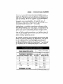
WORST-CASE METHOD
A system of drives and motors places the greatest demand on a
power supply when each motor produces the maximum shaft
power it can deliver, and all motors turn at the same time. For
the power supply, this is the "worst-case" situation. There are
no other times when the power supply must provide this much
power.
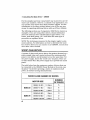
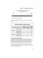
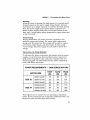
The table below lists the maximum number of drives that can
be connected to the OEM300 Power Module in the worst-case
situation-each drive operating a motor at maximum shaft
power; all motors turning simultaneously.
WORST-CASE NUMBER OF DRIVES
NUMBER
OF DRIVES
MOTOR SIZE
OEM5?-40'~_!/2 Stack
SIZE 23
SIZE 34
40
OEM5?-51··MO
1 Stack
OEM5? -83-MO
2 Stack
OEM83-62··MO
_.
1 Stack
OEM83-93··MO
2 Stack
OEM83-135-MO
3 Stack
-_.
---
--
5
4
3
3
----
--
-------
_.-
2
2
OEM300 • ® Calculating How Many Drives
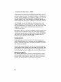
CALCULATION METHOD
In most applications, the worst-case situation described above
never occurs. Conditions where all motors in a system produce
maximum shaft power, all at the same time, are extremely rare.
Instead, it is more common for the motors to use power at
different levels: one may be accelerating, another stopped, and
others moving at constant velocity or decelerating.
If you consider the move profiles of all motors in your system,
and evaluate the amount of peak and average power the motors
require, you will probably find that you can operate more drives
and motors from one OEM300 than the worst-case numbers
suggest. Details on how to perform these calculations are given
below.
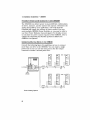
WHERE POWER IS USED IN A MOTION CONTROL SYSTEM
A motor can be in one of four states: stopped, accelerating,
slewing, or decelerating. The power supply must satisfY the
motor's power requirements, which are very different during
each of these states.
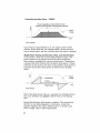
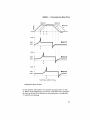
A sketch of a typical move profile is shown below.
Time
Typical Move Profile
In the following sections, we will see how the drive and motor
use the power they get from the power supply. Then, we will
examine the amount of power required by the drive and motor
during each part of a move.
41
® Calculating How Many Drives • OEM300
Copper Losses and Drive Losses
Two types of power losses always exist, whether a motor is in
motion or stopped-copper losses and drive losses. Their values
remain approximately constant, regardless of the speed at
which the motor turns. If the motor is not moving, these are the
only losses present.
Copper losses are caused by resistance to current flow in the
copper windings of the motor. A step motor that is stopped has
a current flowing in it to maintain holding torque; approximately the same amount of current flows when the motor is in
motion.
The copper losses are calculated as I2R-the square of the
current in the windings, multiplied by the resistance of the
windings. Since the current stays the same, whether the motor
is moving or stopped, the copper losses are constant. They are
usually small, approximately 10 to 15 Watts, because the
resistance of the windings is low.
Drive losses occur during normal operation of the drive. The
drive receives power from the power supply, and sends most of
that power to the motor. Some of the power, however, is lost as
heat in the drive when resistors and other components heat up.
Power dissipated as heat in the drive constitutes the drive
losses. These are usually small, approximately equal to the
copper losses. They are proportional to the current the drive
delivers. Since this current is fairly constant, drive losses are
also constant-they do not change when motor speed changes.
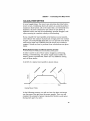
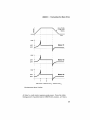
Copper losses and drive losses are shown in the drawing below.
Notice that these losses are constant, whether the motor is
moving or stopped.
42
OEM300 • ® Calculating How Many Drives
Power Dissipated in Motor's Copper Windings &
Power Dissipated in Drive
/ / -
- -}- -
-
- " "
/
---
/
Move
'~profile
"
/
-_.
Time
Copper Losses and Drives Losses
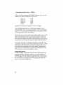
The following table lists the values for drive losses and copper
losses.
COPPER LOSSES and DRIVE LOSSES
Copper
Drive TOTAL
(COPPER
Loss(W) Loss(W) + DRIVE)
OEM SERIES MOTORS
SIZE 23
OEM57-40-MO
9
9
OEM57 -51-MO
11
OEM57-83-MO
9
11
13
15
20
27
OEM83-62-MO
----~.-
SIZE 34
..
--.---
- .. -
OEM83-93-MO
OEM83-135-MO
.-
13
14
15
---
---~.-
.-~
--
---------.~
18
22
22
28
34
42
-------
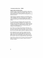
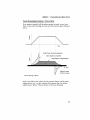
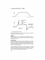
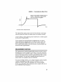
Core Losses Caused by Motion
When the motor is in motion, some power is lost because of the
movement of the motor. The moving magnetic fields in the
motor will induce eddy currents in the motor's iron core; these
eddy currents cause heating in the core. The power supply
delivers the power that ends up as heat in the motor's core.
The power losses caused by eddy current induction are called
core losses (they are also known as iron losses). Core losses are
shown in the drawing below.
43
® Calculating How Many Drives • OEM300
Power Dissipated as Heat in Motor's CoreCaused by Moving Motor Inducing Eddy Currents
""
/
/
/
~Move
" "
Profile
"
Time
Core Losses
Core losses are proportional to z)2, the square of the motor's
velocity. Notice that they can change rapidly during acceleration or deceleration, and are constant when the motor is slewing
Shaft Power During Acceleration. Slew. and Deceleration
To accelerate a load, the motor's shaft produces torque. The
power required to accelerate the load is called shaft power
(since torque multiplied by velocity equals power). During slew,
a system with little friction will not require shaft power. If there
is friction in the system, the motor must produce shaft power to
overcome the friction. Shaft power is shown in the drawing
below.
/
. - - Acceleration
Friction ~
Regeneration ------.
""
~ Move
" "
Profile
""
Time
Shaft Power
Notice that shaft power rises at a constant rate during acceleration. and. if friction is negligible. will be close to zero during
slew.
During deceleration, shaft power is negative. This means that
the drive is not delivering power to the motor. In fact, the
opposite happens: the motor delivers power to the drive and
power supply. This is called regeneration.
44
OEM300 • ® Calculating How Many Drives
POWER REQUIREMENTS DURING A TYPICAL MOVE
If we make a graph of all the places power is used. as we have
done in the next drawing. we can see where power goes during a
move.
Time
Shaft Power During Acceleration
/
Core
L~sses During Slew
/
Deceleration / Regeneration
..
\
7"
lIme
Copper Losses
& Drive Losses
Power During a Move
And. if we add up the values for the various losses, shaft power,
regeneration, etc., we get a graph of the power that the power
supply must deliver. This is shown in the next drawing.
45
® Calculating How Many Drives • OEM300
Time
I • __ Power Required
at Peak
Power Required
for Slew
'';.
Regeneration
------+
Power Required
When Stopped
i
Time
Power Required During a Move
Using the drawings above. we can discuss the power required
during each part of a move profile.
Stopped
When the motor is not moving. power is dissipated in copper
losses and drive losses. The power supply must deliver power to
replace these losses.
Accelerating
During acceleration. the motor develops shaft power. Because
the motor is moving. core losses start to dissipate power. and
playa larger role as speed increases. Copper losses and drive
losses are still present. The power supply must deliver enough
power for all these purposes.
In most applications. the period of time peak power is actually
required is very brief-often just a few thousandths of a second.
There is usually enough stored energy in the power supply's
capacitors to meet this brief power demand.
46
OEM300 • ® Calculating How Many Drives
Slewing
When the motor is slewing. the load moves at a constant speed.
Demand placed on the power supply drops sharply. because
shaft power is no longer required to accelerate the load. During
slew. the power supply must replace losses caused by core
losses; it must supply shaft power to overcome friction in the
load; and. it must replace power dissipated in copper losses and
in the drive itself.
Decelerating
During deceleration. the motor becomes a generator. and
produces regenerated energy. The motor sends regenerated
energy onto the power bus; this energy will be used to replace
core losses. copper losses. and drive losses. If there is still
excess energy. the power supply must be able to absorb this
energy.
CALCULATING THE POWER REQUIRED
To calculate the power your system will require from the power
supply. you need to know three numbers: power required at
peak. power required for slew. and power required when the
motor is stopped. The table below lists the power required by
each OEM Series step motor.
POWER REQUIREMENTS MOTOR SIZE
OEM57-40-MO
SIZE 23
OEM57-51-MO
-~------
-
OEM57 -83-MO
OEM83-62-MO
SIZE 34
OEM83-93-MO
OEM83-135-MO
OEM SERIES MOTORS
STOP
(W)
18
22
22
28
34
42
~---
SLEW
(W)
46---- ---54
48
67
75
89
-~----
PEAK
(W)
-
-
74
101
110
115
160
189
- -
-------
These figures are for motors that are operating at maximum
power. If your motors operate at less than maximum power. the
figures for peak and slew power will be lower.
47
® Calculating How Many Drives • OEM300
To determine the power that the OEM300 must deliver to your
system at any given time, first determine where each motor is in
its move profile-stopped, accelerating, slewing, or decelerating.
Use the numbers from the table above to approximate the
number of Watts each motor reqUires at that time. Add up the
Watts required by each motor to obtain the total power demand.
The OEM300 can provide 200W on a continuous basis, and
300W peak for up to 30 seconds (with a 10% duty cycle). Identify the periods when your system requires the most power, and
compare the power required with the amount of power the
OEM300 can deliver.
Remember, there is a reservoir of additional power stored in the
capacitors of the OEM300. If the peak power demand during
acceleration of some motors briefly exceeds 300W, the OEM300
may still be able to deliver enough power, provided that the
period of peak demand is short enough.
A
DESIGN EXAMPLE
To illustrate the calculation method, we will determine how
many OEM650 drives can be connected to one OEM300 Power
Module, when each drive runs an OEM57-83 motor (a 23 frame
size 2-stack step motor).
Because the number of drives that can be connected depends
on the motors' move profiles, we will look at two situations. The
first example has move profiles that occur simultaneously. The
second example has move profiles that occur at different times.
Simultaneous Moves
The drawing below shows the move profile and power requirements in a system where three motors Simultaneously accelerate until they reach maximum power, then move at constant
velocity. We assume there is no friction in the system.
48
OEM300 • ® Calculating How Many Drives
Move Profile
,/'ofAIiThree
Motors
Time
110W
Motor #1
48W
22W
110W
I
~
Motor #2
48W
22W
110W
Motor #3
48W
22W
t1
t2
Total Power = 330W at Time t 1; 144Wat Time t2
Simultaneous Move Profiles
At time f1. each motor requires peak power. From the table
listing power requirements for OEM Series motors. we find a
49
® Calculating How Many Drives • OEM300
value of 110W at peak for the OEM57-83 motor. Next, we add
together the power required by each motor:
Motor #1
Motor #2
Motor #3
TOTAL
llOW
llOW
1 lOW
330W
We find the total power required at time t1 is 330W.
The OEM300 is specified as a 300W power supply. Can it
provide 330W? Yes, because the duration of time that 330W is
required is very brief; the OEM300 will use extra power stored
in its capacitors to meet this demand.
Notice that every motor's peak power requirements occur at the
same time. Because of this, we can only run three motors of
this size. This is the same number that is listed in the worstcase table for OEM57-83 motors. The method discussed in this
section was used to find the numbers in the worst-case table.
At time t2, each motor is slewing and requires only 48W. The
total power required to operate the system at this time is 144W.
This means that most of the time this system operates, less
than half of the capability of the Power Module is being used.
The next section shows how to use the full capabilities of the
Power Module, and operate additional drives.
Independent Moves
In this example, we consider the same three motors as in the
previous example. This time, however, the move profiles are
staggered, so that the peak power requirements of each motor
occur at different times. Move profiles and power requirements
for each motor are shown in the next drawing. (We assume
there is no friction during slew.)
50
OEM300 • ® Calculating How Many Drives
Motor #1
Ii'
Motor #2
---------~
.... ,", ...I "" ... "" '" "r.'.II
•• 1,
.' ,
"'j ,
1 •• '
••••
,
(
1
I
1
1
I',
1
Motor #3
'
/
.1·..,
,
••••
1
1
,
••••
"
'
Time
110W
Motor #1
48W
22W
110W
Motor #2
48W
22W
110W
Motor #3
48W
22W
t3
Total Power = 206W at Time t3
Independent Move Profiles
In this system. when Motor # 1 reaches its peak power at time
f1. Motor #2 is beginning to accelerate, and Motor #3 is stopped.
At time f3. Motor #3 accelerates to its peak power. and Motors
# 1 and #2 are slewing.
51
® Calculating How Many Drives • OEM300
The peak power required by this system occurs at time t3.
Motors # 1 and #2 each require 48W while slewing. Motor #3
requires 110W during its moment of peak power. (These numbers can be found in the Power Requirements table.)
We add each motor's power requirements:
Motor #1
Motor #2
Motor #3
TOTAL
48W
48W
110W
206W
The total power the three motors and drives require at time t3 is
206W.
By staggering the move profiles, we have substantially reduced
the peak power requirements of the total system. A fourth motor
and drive could be added. The OEM300 would easily have the
capability to provide the necessary power, no matter when the
fourth motor's peak power demand occurred.
Even more drives and motors can be added. If the moves are
organized so that some motors are stopped while others are
running. the peak demand will be reduced. (Remember that a
stopped motor still requires power-in this example, 22WJ. The
peak demand will also be reduced if some motors operate at a
level that requires less than full peak or full slew power.
UNUSUAL POWER REQUIREMENTS
So far. the explanation of the calculation method has assumed
that the power required during slew is substantially less than
that required at peak acceleration. This is not always the case.
For example, the following drawing shows a graph of the power
reqUired by a motor while it moves a load against a large
amount of friction.
52
OEM300 • ® Calculating How Many Drives
r
Moving a load against a large amount of
friction - slew power is much greater
than when friction is negligible
Time
Unusual Power Requirements
The demand for power rises as the load accelerates, and stays
near the peak level while the load moves at constant velocity.
A motor lifting a load against gravity would have a similar graph
for its power requirements.
If your system has unusual power requirements, you must
make appropriate adjustments to the figures given earlier for
power required by OEM Series motors. Or, use the measurement method discussed in the next section, and determine the
actual current requirements.
MEASUREMENT METHOD
The measurement method empirically measures actual current
flowing from a power supply to each drive. To use the measurement method, you must first make a working prototype of your
system, and measure the current required by each drive as the
motors operate. You can then compare the total current required with that available from the OEM300.
For your prototype system, use a large temporary power supply,
capable of providing enough current for all drives in your
system at 75VDC. Once you determine the current requirements, you will replace the temporary power supply with one or
more OEM300 Power Modules.
53
® Calculating How Many Drives • OEM300
Use a DC current probe to measure the current going from the
power supply to each drive. (Currents going from the drive to
the motor are not relevant in this procedure; you do not need to
measure them.)
Current
Probe
Voltage
Probe
OEM
Series
Drive
,/
Motor
'--_-+-, B
ool=====hA
Probe Amplifier
D
000
Oscilloscope
Setup for Current Measurement
You need to find two values: the total peak current demand;
and the duration, or duty cycle, of that total peak demand. The
total current demand will probably be changing continuously.
One way to locate the peak demand periods and find their duty
cycles is to connect the current probes to a storage oscilloscope.
For any given time, you can then add up the demand from each
drive to obtain the total demand. You can also measure the
duration of the peak demand, find how frequently it occurs, and
calculate its duty cycle.
The OEM300 is rated to deliver current at these levels:
2.7A
4.0A
54
RATED CURRENT
Continuous
Peak (30 sec; 10% duty)
OEM300 • is) Calculating How Many Drives
Current levels that activate the OEM300's short circuit protection are shown in the next table.
SHORT CIRCUIT PROTECTION
Shutdown Within ....
Current Level:
6A
3 seconds
9A
Immediate
With the results of your current probe measurements. and the
current levels listed above. determine how many drives you can
connect to each OEM300. Try to keep the current produced by
the OEM300 within the rated levels.
What happens when your system operates on the borderline,
and occasionally requires more than 4 Amps of current? The
answer depends on the duration and level of the excess current
demand. If asked to deliver excess current, the OEM300 will do
so for brief periods. Voltage will stay very near the rated voltage
of 75VDC.
However. there are two possible consequences if the OEM300
operates outside its specified range. The first is related to overtemperature protection. If the OEM300 continually provides
current in excess of 4.0 Amps, it may become excessively hot.
The OEM300 will not be damaged, but when its heatplate
temperature exceeds 60°C, the over-temperature protection
circuit will shut down the output of the OEM300.
The second potential problem is related to the short circuit
protection feature. The OEM300 will produce currents above
4.0 Amps, to satisfY brief demands; but, if it produces 6.0
Amps, the short circuit protection feature will shut down the
output within seconds. If the current reaches 9.0 Amps, however briefly, the OEM300 will shut down immediately.
Operating the OEM300 beyond its specified range can cause
unpredictable results. Therefore, to achieve optimum performance from the Power Module. connect the appropriate number
of drives.
55
® Calculating How Many Drives • OEM300
56
c
H
A
p
T
E
R
Troubleshooting
WARNING
NO USER SERVICEABLE PARTS INSIDE THE OEM300!
The OEM300 contains potentially lethal voltages. Do not attempt to repair it.
Return it to Compumotor for any repairs.
POSSIBLE PROBLEMS
The first section below gives troubleshooting information for an
OEM300 that does not have drives connected to it. Use the
information in the second section to help you diagnose problems in a system with motors, drives and an OEM300.
No DRIVE IS CONNECTED; OEM300 WILL NOT TURN ON
With AC power connected to the OEM300, the LED and 75VDC
output should be as follows:
NORMAL OPERATION WITH AC POWER CONNECTED
LED:
75VDC OUTPUT:
Should be Illuminated
Should Measure 75VDC ± 5%
If the above conditions are not true, there are three possible
problems:
PROBLEM
No AC power
Thermal Shutdown
Defective OEM300
SOLUTION
Check AC at OEM300 AC Input
Cool OEM300 below 30°C (86°F);
Cycle AC Power
Return OEM300 to Compumotor
57
([J Troubleshooting • OEM300
DRIVE IS CONNECTED; OEM300 WILL NOT POWER DRIVE
Check to see if the LED is illuminated. If it is not, use the
information in the first table below. If it is illuminated, use the
information in the second table.
LED is OFF -
OEM300 Does Not Power Drive
Use an AC voltmeter to verify
presence of AC power at AC
input of OEM300.
Wrong Jumper
Configuration
System will not turn on. or will
not stay on.
120VAC: Install jumper
240VAC: Remove jumper
Thermal Shutdown
due to OverTemperature
System ran properly, but shut
down unexpectedly when
heatplate exceeded 60°C
(140°F). LED is off. OEM300
will not restart.
Cool OEM300 below 30°C
(86°F). Cycle AC power.
Restart OEM300.
Damaged OEM300
OEM300 will not turn on,
even though AC power is
present at input, and
heatplate temp is below 30°C
(86°F).
Return OEM300 to
Compumotor.
LED is ON -
OEM300 Does Not Power Drive
When system is turned on,
OEM300 shuts down
immediately. LED stays on.
Solve short circuit problem in
connected equipment. Cycle
AC power to restart system.
Overvoltage or
Damaged OEM300
When turned on with motor
not moving, system runs for
approx. 1/2 second, then
OEM300 shuts down. LED
stays on.
Return OEM300 to
Compumotor.
Excessive
Regeneration
When turned on, system runs
until regeneration occurs.
OEM300 shuts down during
regeneration. LED stays on.
Adjust move profile or load
characteristics to keep
regeneration within
specifications. Cycle AC
power and restart system.
Drive is not
connected
OEM300 is on. 75VDC output
measures 75VDC. LED is on.
But drive is off.
Check cable connections.
Use a voltmeter to verify
75VDC is present at drive
input.
Wrong Jumper
Configuration
Motor operates poorly, or
does not run at all.
120VAC: Install jumper
240VAC: Remove jumper
I
58
OEM300 • (j) Troubleshooting
RETURNING THE OEM300 TO COMPUMOTOR
If your OEM300 has failed. you must return it for replacement
or repair. If you return your OEM300 for repairs or upgrades.
use the following steps:
1. Get the serial number and the model number of the defective
unit(s). and a purchase order number to cover repair costs in
the event Parker Compumotor determines the unit is out of
warranty.
2. Before you ship the unit to Parker Compumotor. have someone from your organization with a technical understanding of
the OEM300 and its application include answers to the following questions:
• What is the extent of the failure/reason for return?
• How long did it operate?
• How many units are still working?
• How many units failed?
• What was happening when the unit failed (i.e .. installing the
unit. cycling power. starting other equipment. etc.)?
• How was the product configured (in detail)?
• What. if any. cables were connected. and how?
• With what equipment is the unit connected?
• What was the application?
• What was the system sizing (speed. acceleration. duty cycle.
inertia. torque. friction. etc.)?
• What was the system environment (temperature. enclosure.
spacing. unit orientation. contaminants. etc.)?
• What upgrades are required (hardware. user gUide)?
3 . Call Parker Compumotor's Applications Engineering Department at 800-358-9070 for a Return Material Authorization
(RMA) number. Returned products cannot be accepted without
an RMA number.
4. Ship the unit to:
Parker Compumotor Corporation
5500 Business Park Drive
Rohnert Park. CA 94928
Attn: RMA # xxxxxxx
59
(iJ Troubleshooting • OEM300
60
I
N D E
x
A
o
AC Input Ground 15
AC Input Secifications 21-24
AC Input Voltage 12
AC Power Connection 11
Accelerating-Power Requirements
46
Additional Ventilation 37-38
Ambient Temperature Limits 24, 37
DC4 18
DC Output Connector 13
DC Output Specifications 22
Decelerating-Power Requirements
47
Description of OEM300 2
Design Issues 3
cooling OEM300 4
how many drives? 4
Dimensions 7
Drive Losses 42
Drives-How many can OEM300
operate? 39-55
Duty cycle 22
B
Bench test 6
Bus 14
c
Cable Length 14
Calculating # of Drives to Connect
39-55
Calculating Power Requirements 47
Calculation Method 41-53
Cautions VI
Compumotor DC 4 18
Conduit 18
Connecting Multiple Drives 16
Connectors 6
Continuous Power Output 22
Controlling electrical noise 17
Convection Cooling 36-38
Copper Losses 42
Core Losses 43
Current limiter 22
Current probes 54
Current sharing 17
Cycle power-definition 26
E
EARTH ground 15
Efficiency 22
Electrical Noise Control 17
Electro Magnetic Interference 18
Electromagnetic radiation 18
EMI 18
EMI filters 18
External filter 17
Extra capacitors 18
F
Fan, for ventilation 37
Features of OEM300 2
Filters 17
5 Pin Connector 6, 12
61
Index • OEM300
G
Green LED 19
Ground loops 15
Ground pins 13
Grounding 15
H
Heat sinking surface 35
Heatplate Cooling 33-36
Heatplate Temperature Limit 24, 34
Heatsink Calculations 35
Heatsink Problems 35-36
How Many Drives to Connect? 3955
Hysteresis 27
Input Connector 12
Input Filter 17, 21
Input ground 15
Input Specifications 21-24
Input Voltage 21
Inrush Current 22
Installation 7-18
Internal connections 14
J
Jumper wire 11, 58
L
Latched-Definition 26
LED 19
Linear power supply 18
Load regeneration 28
M
Maximum Ambient Temperature 24
Maximum Heatplate Temperature
24,27
Maximum number of drives 40
Measurement Method 53-55
Measuring Heatplate Temperature
34
Minimum Ambient Temperature 24
62
Minimum Spacing 8
Motors-Power Requirements 47
Mounting 7-11
Air circulation 11
Attachment to Heatsink 10
Heat-producing equipment 9
Minimum Spacing 7
Multiple OEM300s 8
Panel Layout 7
Ventilation 11
Moving Air-Temperature Limits 24
Multiple pins 13
N
Noise reduction 17
Input Filter 17
Linearpowersupp~ 18
Output Cables 18
Output Filter 18
Switching power supply 17
o
OEM Series
basic features
design intentions
OEM Series Step Motors-Power
Requirements 47
ON/OFF switch 19
Output Connection 13
Output Connector 13
Output Current 22
Output Filter 18
Output Grounds 15, 22
Output Pins 13
Output Power. See Power Output
Output Specifications 22
Output Voltage 22
Over-Temperature Protection
23,27
Overvoltage Protection 23, 31-32
threshold values 31
troubleshooting 31
p
Paint, and heatsink 36
Panel Layout 8
OEM300 • Index
Parallel OEM300s 17
Peak Power Output 22
Plug
AC input 12
DC output 13
Power Bus 14
Power cabling 14
Power Connection 11
Power Dump 23, 28-31
OEM650 power dump 31
Power Output 22
continuous 22
duty cycle at peak 22
peak 22
Power Required During Move 45
Power Requirements-TABLE 47
Problems-Troubleshooting 57
Protective Circuits 3, 25-32
Providing Additional Ventilation 3738
R
Reducing electrical noise 17
Regeneration 28
Removable connector
AC input 12
DC output 13
Reserved pin 13
Returning OEM300 to Compumotor
59
RMA number 59
s
Safety considerations 15
75VDC output grounds 15
75VDC pins 13
Shaft Power 44
Shielded power cables 18
Ship Kit 6
Short Circuit Protection 23, 25-26
current levels 26
response time 26
Shutdown temperature 27
6 Pin Connector 6, 13
Slewing-Power Requirements 47
Spacing 8
Specifications for OEM300 21-24
Step Motors-Power Requirements
47
Still Air Temperature Limits 24
Stopped Power Requirements 46
Switching Frequencies 17
Switching power supply 17
T
Temperatures-operating 24
Thermal hysteresis 27
Thermal interface 33
Thermal mass 33
Thermal probe 34
Thermal switch 27
Trip Temperature 27
Troubleshooting 57-59
Turning OEM300 on 19
Typical move profile 41
u
Unusual Power Requirements 52
User Guide 6
v
Ventilation 37-38
Voids in Thermal Interface 36
Voltage Range-AC Input 12
Voltage Regulation 22
w
Warnings VI
Warped Heatsink 35
Where Power is Used 41
Wire Size-AC Input 12
Wire Size-DC Output 13
Worst-Case Method 40
63
OEM300 POWER MODULE
The OEM300 is NOT a
general purpose power
supply. Use it only with
Compumotor OEM
Series Microstepping or
Servo Drives.
WARNING
NO USER SERVICEABLE PARTS INSIDE
The OEM300 contains potentially lethal
voltages! Do not attempt to repair it. Return
the OEM300 to Compumotor for repairs.
HEATPLATE COOLING
W$iijiimi ---......
Attach Power
Module's heatplate
to a heatsink or
heat sinking
surface
~ :
• You must provide a Thermal
Interface to cool the heatplate
• Use silicone thermal joint compound or thermal gasket
• Maximum Temp 60°C (140°F)
AMBIENT AIR COOLING
• Keep 2" clearance
around top, bottom, and sides
AIR TEMP LIMITS:
• STILL AIR:
35°C (95°F)@200W
40°C(1 04°F)@170W
• MOVING AIR
45°C(113°F)@200W
50°C(122°F)@170W
INPUT POWER
• 90-132VAC with Jumper
Installed
• 180-265VAC with Jumper
Removed
• DO NOT USE 132-180VAC
INPUT CONNECTOR:
• 5 Pin Removable Connector
• 16 AWG Recommended
You must connect the EARTH
terminal to EARTH GROUND!
(Chassis, cover, EARTH, GND
pins are connected internally)
OUTPUT POWER
• 75VDC ± 5%
• 2.7A/200W Continuous
• 4.0A/300W Peak
(30 sec., 10% Duty Cycle at Peak)
• Two 75VDC pins, internally connected
OUTPUT CONNECTOR:
• 6 Pin Removable Connector
• Use16 AWG if < 10 ft., 14 AWG if> 10 ft.
DO NOT CONNECT MUL TlPLE OEM300s IN
PARALLEL! The will not share the load.
PROTECTIVE CIRCUITS
•
•
•
•
SHORT CIRCUIT PROTECTION - Latched
POWER DUMP - Turns on at 85VDC
OVER-TEMPERATURE - Unit shuts down @ 60°C; Latched; Cool to 30°C
OVERVOLTAGE - Shuts down output after 0.5 sec overvoltage; Latched