1
GUARDIAN
A5-6000 Dispensing System
)RUXVHZLWKQRQÀDPPDEOHIRDPDQGSRO\XUHD
1RWIRUXVHLQH[SORVLYHDWPRVSKHUHV
USER MANUAL
0D[LPXPÀXLGZRUNLQJSUHVVXUH
SVL03DEDU
EN
T IS P R
CHINESE
PATENT
HI
ZL 200630130159.1
T
T
M
CT ED B
Y
U.S.A.
PATENT
D546,840
S E Q UI P
T IS P R
CT ED B
Y
HI
EN
TE
O
M
TE
O
S E Q UI P
Important Safety Instructions
Read all warnings and instructions in
this manual. Save these instructions.
Table Of Contents
Section 1 Installation
Warnings ............................................................................................................................................................
Introduction ........................................................................................................................................................
Standard Equipment ..........................................................................................................................................
Technical Data .........................................................................................................................
Equipment Assembly ..........................................................................................................................................
1
5
6
7
8
Section 2 Operation
Start-up Instructions ...........................................................................................................................................
Shut–down Instructions ......................................................................................................................................
14
18
Section 3 General Information
Assembly Drawings .............................................................................................................................................
Sub Assembly Drawings ......................................................................................................................................
Maintenance ........................................................................................................................................................
Troubleshooting ...................................................................................................................................................
Options ................................................................................................................................................................
22
29
36
37
40
Section 4 Warranty and Reference Information
Limited Warranty Policy ............................................................................................................
41
Technical Assistance ................................................................................................................
42
For Your Reference ............................................................................................. INSIDE BACK COVER
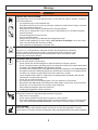
Warnings
The following warnings are for the setup, use, grounding, maintenance, and repair of this equipment. The exclamation
SRLQWV\PERODOHUWV\RXWRDJHQHUDOZDUQLQJDQGWKHKD]DUGV\PEROUHIHUVWRSURFHGXUHVSHFL¿FULVN5HIHUEDFNWRWKHVH
ZDUQLQJV$GGLWLRQDOSURGXFWVSHFL¿FZDUQLQJVPD\EHIRXQGWKURXJKRXWWKHERG\RIWKLVPDQXDOZKHUHDSSOLFDEOH
WARNING
ELECTRIC SHOCK HAZARD
,PSURSHUJURXQGLQJVHWXSRUXVDJHRIWKHV\VWHPFDQFDXVHHOHFWULFVKRFN
Turn off and disconnect power cord before servicing equipment.
Use only grounded electrical outlets.
Use only 3-wire extension cords.
Ensure ground prongs are intact on sprayer and extension cords.
Do not expose to rain. Store indoors.
TOXIC FLUID OR FUMES HAZARD
7R[LFÀXLGVRUIXPHVFDQFDXVHVHULRXVLQMXU\RUGHDWKLIVSODVKHGLQWKHH\HVRURQVNLQLQKDOHGRU
swallowed.
5HDG06'6¶VWRNQRZWKHVSHFL¿FKD]DUGVRIWKHÀXLGV\RXDUHXVLQJ
6WRUHKD]DUGRXVÀXLGLQDSSURYHGFRQWDLQHUVDQGGLVSRVHRILWDFFRUGLQJWRDSSOLFDEOHJXLGHlines.
Always wear impervious gloves when spraying or cleaning equipment.
PERSONAL PROTECTIVE EQUIPMENT
You must wear appropriate protective equipment when operating, servicing, or when in the operating
DUHDRIWKHHTXLSPHQWWRKHOSSURWHFW\RXIURPVHULRXVLQMXU\LQFOXGLQJH\HLQMXU\LQKDODWLRQRIWR[LF
fumes, burns, and hearing loss. This equipment includes but is not limited to:
Protective eyewear
&ORWKLQJDQGUHVSLUDWRUDVUHFRPPHQGHGE\WKHÀXLGDQGVROYHQWPDQXIDFWXUHU
Gloves
Hearing protection
SKIN INJECTION HAZARD
+LJKSUHVVXUHÀXLGIURPJXQKRVHOHDNVRUUXSWXUHGFRPSRQHQWVZLOOSLHUFHVNLQ7KLVPD\ORRNOLNH
MXVWDFXWEXWLWLVDVHULRXVLQMXU\WKDWFDQUHVXOWLQDPSXWDWLRQGet immediate surgical treatment.
Do not point gun at anyone or at any part of the body.
Do not put your hand over the spray tip.
'RQRWVWRSRUGHÀHFWOHDNVZLWK\RXUKDQGERG\JORYHRUUDJ
Close material shutoff valves, and then shut off or disconnect air supply when not spraying.
Follow Pressure Relief Procedure in this manual, when you stop spraying and before cleaning,
FKHFNLQJRUVHUYLFLQJHTXLSPHQW
1
Warnings
WARNING
FIRE AND EXPLOSION HAZARD
)ODPPDEOHIXPHVVXFKDVVROYHQWDQGSDLQWIXPHVLQZRUNDUHDFDQLJQLWHRUH[SORGH7RKHOSSUHYHQW¿UHDQGH[SORVLRQ
Use equipment only in well ventilated area.
Eliminate all ignition sources; such as pilot lights, cigarettes, portable electric lamps, and plastic
drop cloths (potential static arc).
.HHSZRUNDUHDIUHHRIGHEULVLQFOXGLQJVROYHQWUDJVDQGJDVROLQH
'RQRWSOXJRUXQSOXJSRZHUFRUGVRUWXUQSRZHURUOLJKWVZLWFKHVRQRURIIZKHQÀDPPDEOH
fumes are present.
*URXQGDOOHTXLSPHQWLQWKHZRUNDUHD
Use only grounded hoses.
+ROGJXQ¿UPO\WRVLGHRIJURXQGHGSDLOZKHQWULJJHULQJLQWRSDLO
,IWKHUHLVVWDWLFVSDUNLQJRU\RXIHHODVKRFNstop operation immediately. Do not use equipment until you identify and correct the problem.
.HHSDZRUNLQJ¿UHH[WLQJXLVKHULQWKHZRUNDUHD
PRESSURIZED ALUMINUM PARTS HAZARD
Do not use 1,1,1-trichloroethane, methylene chloride, other halogenated hydrocarbon
VROYHQWVRUÀXLGVFRQWDLQLQJVXFKVROYHQWVLQSUHVVXUL]HGDOXPLQXPHTXLSPHQW6XFK
use can cause serious chemical reaction and equipment rupture, and result in death,
VHULRXVLQMXU\DQGSURSHUW\GDPDJH
EQUIPMENT MISUSE HAZARD
0LVXVHFDQFDXVHGHDWKRUVHULRXVLQMXU\
'RQRWRSHUDWHWKHXQLWZKHQIDWLJXHGRUXQGHUWKHLQÀXHQFHRIGUXJVRUDOFRKRO
'RQRWH[FHHGWKHPD[LPXPZRUNLQJSUHVVXUHRUWHPSHUDWXUHUDWLQJRIWKHORZHVWUDWHGV\VWHP
component. See Technical Data in all equipment manuals.
8VHÀXLGVDQGVROYHQWVWKDWDUHFRPSDWLEOHZLWKHTXLSPHQWZHWWHGSDUWV6HHTechnical Data in
DOOHTXLSPHQWPDQXDOV5HDGÀXLGDQGVROYHQWPDQXIDFWXUHU¶VZDUQLQJV)RUFRPSOHWHLQIRUPDtion about your material, request MSDS forms from distributor or retailer.
&KHFNHTXLSPHQWGDLO\5HSDLURUUHSODFHZRUQRUGDPDJHGSDUWVLPPHGLDWHO\ZLWKJHQXLQH
manufacturer’s replacement parts only.
Do not alter or modify equipment.
Use equipment only for its intended purpose. Call your distributor for information.
5RXWHKRVHVDQGFDEOHVDZD\IURPWUDI¿FDUHDVVKDUSHGJHVPRYLQJSDUWVDQGKRWVXUIDFHV
'RQRWNLQNRURYHUEHQGKRVHVRUXVHKRVHVWRSXOOHTXLSPHQW
.HHSFKLOGUHQDQGDQLPDOVDZD\IURPZRUNDUHD
Comply with all applicable safety regulations.
MOVING PARTS HAZARD
0RYLQJSDUWVFDQSLQFKRUDPSXWDWH¿QJHUVDQGRWKHUERG\SDUWV
Keep clear of moving parts.
Do not operate equipment with protective guards or covers removed.
3UHVVXUL]HGHTXLSPHQWFDQVWDUWZLWKRXWZDUQLQJ%HIRUHFKHFNLQJPRYLQJRUVHUYLFLQJHTXLSment, follow the Pressure Relief Procedure in this manual. Disconnect power or air supply.
BURN HAZARD
(TXLSPHQWVXUIDFHVDQGÀXLGWKDW¶VKHDWHGFDQEHFRPHYHU\KRWGXULQJRSHUDWLRQ7RDYRLG
VHYHUHEXUQVGRQRWWRXFKKRWÀXLGRUHTXLSPHQW:DLWXQWLOHTXLSPHQWÀXLGKDVFRROHGFRPSOHWHO\
2
Warnings
To prevent exposing ISO to moisture:
Isocyanate Hazard
Spraying materials containing isocyanates creates
potentially harmful mists, vapors, and atomized
particulates.
Read material manufacturer’s warnings and
PDWHULDO06'6WRNQRZVSHFL¿FKD]DUGVDQG
precautions related to isocyanates.
Prevent inhalation of isocyanate mists, vapors, and
DWRPL]HGSDUWLFXODWHVE\SURYLGLQJVXI¿FLHQWYHQWLODWLRQLQWKHZRUNDUHD,IVXI¿FLHQWYHQWLODWLRQLVQRW
available, a supplied-air respirator is required for
HYHU\RQHLQWKHZRUNDUHD
To prevent contact with isocyanates, appropriate
personal protective equipment, including chemically
impermeable gloves, boots, aprons, and goggles, is
DOVRUHTXLUHGIRUHYHU\RQHLQWKHZRUNDUHD
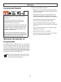
Moisture Sensitivity of
Isocyanates
Isocyanates (ISO) are catalysts used in two component
foam and polyurea coatings. ISO will react with moisture
(such as humidity) to form small, hard, abrasive crystals,
ZKLFKEHFRPHVXVSHQGHGLQWKHÀXLG(YHQWXDOO\D¿OPZLOO
form on the surface and the ISO will begin to gel, increasing in viscosity. If used, this partially cured ISO will reduce
performance and the life of all wetted parts.
7KHDPRXQWRI¿OPIRUPDWLRQDQGUDWHRIFU\VWDOlization varies depending on the blend of ISO,
the humidity, and the temperature.
3
Always use a sealed container with a desiccant dryer
in the vent, or a nitrogen atmosphere. Never store ISO
in an open container.
.HHSWKH,62OXEHSXPSUHVHUYRLU¿OOHGZLWK*UDFR
Throat Seal Liquid (TSL), Part 206995. The lubricant
creates a barrier between the ISO and the atmosphere.
8VHPRLVWXUHSURRIKRVHVVSHFL¿FDOO\GHVLJQHGIRU
ISO, such as those supplied with your system.
Never use reclaimed solvents, which may contain
PRLVWXUH$OZD\VNHHSVROYHQWFRQWDLQHUVFORVHGZKHQ
not in use.
Never use solvent on one side if it has been contaminated from the other side.
$OZD\VSDUNSXPSVZKHQ\RXVKXWGRZQ
Always lubricate threaded parts with Part 217374 ISO
pump oil or grease when reassembling.
Warnings
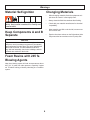
Material Self-ignition
Changing Materials
Some materials may become self-igniting if applied to
WKLFNO\ 5HDG PDWHULDO PDQXIDFWXUHU¶V ZDUQLQJV DQG
material MSDS.
Keep Components A and B
Separate
CAUTION
To prevent cross-contamination of the equipment’s wetted parts, never interchange component A (isocyanate)
and component B (resin) parts. The gun is shipped with
WKH$VLGHRQWKHOHIW7KHÀXLGPDQLIROGÀXLGKRXVLQJVLGHVHDODVVHPEO\FKHFNYDOYHFDUWULGJHDQGPL[
FKDPEHUDUHPDUNHGRQWKH$VLGH
Foam Resins with 245 fa
Blowing Agents
New foam blowing agents will froth at temperatures above
90°F (33 °C) when not under pressure, especially if agitated. To reduce frothing, minimize preheating in a circulation
system.
4
:KHQFKDQJLQJPDWHULDOVÀXVKWKHHTXLSPHQWPXOtiple times to ensure it is thoroughly clean.
$OZD\VFOHDQWKHÀXLGLQOHWVWUDLQHUVDIWHUÀXVKLQJ
&KHFNZLWK\RXUPDWHULDOPDQXIDFWXUHUIRUFKHPLFDO
compatibility.
Most materials use ISO on the A side, but some use
ISO on the B side.
Epoxies often have amines on the B (hardener) side.
Polyureas often have amines on the B (resin) side.
Section 1 - Installation: Introduction
Introduction
The information in this document is intended only to
LQGLFDWHWKHFRPSRQHQWVDQGWKHLUQRUPDOZRUNLQJ
relationship typical use. Each assembly should be
directed by a GlasCraft distributor or made from the
GlasCraft Assembly instructions provided.
Before operating, maintaining or servicing any
GlasCraft system, read and understand all of the
technical and safety literature provided with GlasCraft
products. If you do not have the proper or related
manuals and safety literature for your GlasCraft system,
contact your GlasCraft distributor.
This manual provides information for the assembly, operation, maintenance and service of this GlasCraft product as
XVHGLQDW\SLFDOFRQ¿JXUDWLRQ:KLOHLWOLVWVVWDQGDUGVSHFL¿
cations and procedures, some deviations may be found.
In this GlasCraft technical and safety publication, the
following advisories will be provided where appropriate:
Information about the procedure in progress.
In order to provide our users with the most up-to-date
WHFKQRORJ\SRVVLEOHZHDUHFRQVWDQWO\VHHNLQJWRLPSURYH
products. If a technological change occurs after a prodXFWLVRQWKHPDUNHWZHZLOOLPSOHPHQWWKDWWHFKQRORJ\LQ
IXWXUHSURGXFWLRQDQGLISUDFWLFDOPDNHLWDYDLODEOHWRFXUUHQWXVHUVDVDUHWUR¿WXSGDWHRUVXSSOHPHQW,I\RX¿QG
a discrepancy between your unit and the available documentation, contact your GlasCraft distributor to resolve the
difference.
Is imperative information about equipment protection.
CAUTION
Indicates a hazardous situation that can
result in minor or moderate injury.
WARNING
Careful study and continued use of this manual will provide a better understanding of the equipment and process,
UHVXOWLQJLQPRUHHI¿FLHQWRSHUDWLRQORQJHUWURXEOHIUHH
service and faster, easier troubleshooting.
Indicates a hazardous situation that can
result in death or serious injury.
ELECTRICAL SHOCK HAZARD
Indicates a hazardous situation that can
result in electrical shock or serious injury.
5
Section 1 - Installation: Standard Equipment
Model - A5-6000
Part
Description
GC1750
GC1752
GC1753
A5-6000 UNIT; 220V, 1PH, F
A5-6000 UNIT; 220V, 3PH, F
A5-6000 UNIT; 380V, 3PH, C
GCP2R2*
PROBLER P2 GUN
246075*
POWER LOCK HEATED HOSE
246050*
WHIP HOSE ASSEMBLY
313268
USER MANUAL
206995
FLUID, TSL, 1 QT. BOTTLE
GC0174
TRANSFER KIT; A5 AND A6 UNITS (DOES NOT INCLUDE TRANFER PUMPS
* Purchase separately
Recommended Repair Parts
Part
Description
GC1748
HEATER REPAIR KIT
Related Manuals
Part
Description
312766
T1 2:1 RATIO TRANSFER PUMP INSTRUCTIONS-PARTS
309572
HEATED HOSE INSTRUCTIONS-PARTS
313277
MATERIAL PUMPS INSTRUCTIONS
6
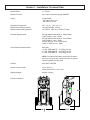
Section 1 - Installation: Technical Data
Material Ratio:
1:1 (Fixed)
Material Viscosity:
200- 2000 Centipoise (Cps) @ AMBIENT
Output:
Pumps Rated:
.042 Gallons Per Cycle
.159 Liters Per Cycle
Operating Temperatures:
0D[LPXPDLUZRUNLQJSUHVVXUH 0D[LPXPÀXLGZRUNLQJSUHVVXUH
(OHFWULFDO5HTXLUHPHQWV
Compressed Air Requirements:
32º F ( 0º C ) - 180º (82 º C )
SVL03DEDU
5$7,2SVL03DEDU
$#9$&K]6LQJOH3KDVH
(cable: 6 AWG, 2 wire + GND)
$#9$&K]7KUHH3KDVH
(cable: 8 AWG, 3 wire + GND)
20 A @ 380 VAC, 50 hz. Three Phase
(cable: 12 AWG, 4 wire + GND)
Base Unit:
1.0 GAL PER MINUTE – 17 CFM @ 100 psi
1.5 GAL PER MINUTE – 24 CFM @ 100 psi
2.0 GAL PER MINUTE – 33 CFM @ 100 psi
NOTE:$VRXWSXWLVLQFUHDVHGDFKLHYHGZFKDPEHU
size on gun or spray tip), pressure drop will be greater.
Heating capability will also drop.
Heaters:
6000 WATT HEATER
Maximum Hose Length:
310 ft. (94.5 m)
(DFK6HFWLRQIW[LQ,'
6KLSSLQJ:HLJKW
OEVNJ
Overall Dimensions:
7
Section 1 - Installation: Equipment Assembly
Guardian Line Installation Guide
GlasCraft Systems are factory assembled. If any
questions arise concerning air or electrical
connections, please refer to illustrations located in
the forward portion of this User Manual or contact
your GlasCraft distributor.
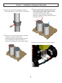
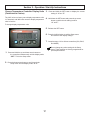
1. Locate Guardian.
'RQRWXVHDQ\TXLFNGLVFRQQHFW¿WWLQJVRQ
the main air line going to the machine!
Check your air-compressor to make sure it is
capable of supplying the maximum amount of air
that the machine requires. All GlasCraft equipment
is rated at 25 CFM (cubic foot per minute) 708
liters @ 90-100 psi (0.62-0.7 MPa, 6.3-7.7 BAR)
do not exceed 125 PSI (0.86 MPa, 8.6 bar).
a. Locate Guardian on a level surface.
b. Do not expose Guardian to rain.
Bolt Guardian to orginanl shipping pallet before
lifting.
c.8VHWKHZKHHOVWRPRYH*XDUGLDQWRD¿[HG location, or bolt to shipping pallet and move with
IRUNOLIW
d. 7RPRXQWRQDWUXFNEHGRUWUDLOHUDQGEROW
GLUHFWO\WRWUXFNRUWUDLOHUEHG
2. Advanced preparation
a. Before beginning any installation, ensure that the
applicator has the desired power supply available,
LH9VLQJOHSKDVH9WKUHHSKDVH
within 10 ft. of were the machine is to be placed.
If the machine needs to be further that 10 ft. from
the power supply, additional lengths of properly
sized electrical cable will be required.
Never use a smaller gauge size than supplied
by the factory!
b. Depending on the electrical setup, it may be
necessary to install an appropriate plug on the end
of the cable. GlasCraft will not supply this plug, as
we are unaware of which style will be needed.
c.&RQVXOWWKHGDWDVKHHWIRUWKHVSHFL¿FXQLWEHLQJ
LQVWDOOHGWRGHWHUPLQHWKHSURSHUEUHDNHUVL]H
needed.
d. You will need to run an air line to the area where
the machine will be placed. consult the data
VKHHWWKHVSHFL¿FXQLWEHLQJLQVWDOOHGWRGHWHUPLQH
how much clean, dry air will be needed to supply
the machine. If the air line is under 25 ft. use a
PLQLPXPRILQ,'SLSHRUKRVH,IWKHDLUOLQH
is longerWKDQIWXVHDPLQLPXPRILQ
pipe or hose. Anything smaller than these
diameters will severly affect the machine’s
8
performance!
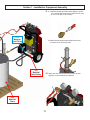
2. Move material drums to the area that the equipment will
be placed, ensuring that they are not sitting directly on
WKHÀRRU6LPSO\SODFHWKHGUXPVRQWRSRIDSDOOHWRU
similar device, so the drum bottoms will not be in
contact with any cold surfaces.
3. Open all boxes that came with the machine and verify
that all items are accounted for.
4. ,QVWDOO<¿OWHUVSURYLGHGLQWUDQVIHUNLW*&LQWR outlets of both transfer pumps (purchase separately.
Be sure to use PTFE tape on the threads.
Section 1 - Installation: Equipment Assembly
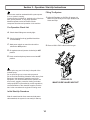
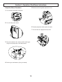
7.0DNHVXUHWKDWWKHSODVWLFFDSVKDYHEHHQUHPRYHG
5. ,QVWDOODPDOHTXLFNGLVFRQQHFW¿WWLQJWRDLULQOHWRI
from the bottom of the pumps and then slide the
transfer pumps into the collars. Tighten the collars,
securing the transfer pumps in place.
/RRVHQWKHLQYHQWSOXJVRQERWKGUXPV
allowing for ventilation. If using a desiccant dryer on
the A side, install it now.
both pumps. Besure to use PTFE tape on the threads.
6. Remove the 2 inch bung caps on both the A and B
side drums. Install the transfer pump
FROODUVEXQJDGDSWHUVLQWRWKHEXQJKROHVPDNLQJ
sure to lubricate the threads with vaseline or
grease, thus enabling easy removal when needed.
8. Remove the metal caps from the material pumps.
9
Section 1 - Installation: Equipment Assembly
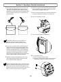
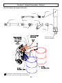
9. Connect one end of each material hose (provided in
WUDQVIHUNLW*&WRWKHLQOHW
¿WWLQJVORFDWHGRQWKHEDFNRIWKHPDFKLQHIt is
highly recommended that you label the (POLY)
hose with BLUE tape and the (ISO) hose with RED
tape to ensure that you don’t put the wrong transfer
pump in the opposite material drum.
POLY
Material
Drum
10. Connect the other end of the material hoses to
the correct transfer pumps. Ensure that they
are not reversed and tighten securely.
10
Section 1 - Installation: Equipment Assembly
11. a. ,QVWDOOWKHIHPDOHTXLFNGLVFRQQHFW¿WWLQJVRQWRWKH
POLY
Material
Inlet Fitting
óLQDLUOLQHVWKDWFDPHLQWKHWUDQVIHUNLWBe sure
to use PTFE tape on the threads.
b. $WWDFKWKHTXLFNGLVFRQQHFW¿WWLQJVWRWKHPDOH
receivers on the transfer pumps.
ISO
Material
Inlet Fitting
12. Attach the other end of the airlines to the far right
regulator on the machines air manifold.
ISO
Material
Drum
11
Section 1 - Installation: Equipment Assembly
13. ,IWKHRSWLRQDOVFXIIMDFNHWLVEHLQJ
16. &RQQHFWWKHLQDLUOLQHRQWKHKRVHDVVHPEO\WR
used (highly recommended, sold separately)
install it over each individual section of hose
before proceeding any further. Securely tape both
HQGVRIVFXIIMDFNHWWRWKHKRVHDVVHPEO\
the air line whip hose on the front of the machine.
14. Locate the thermal couple wire protruding from the
%VLGH¿WWLQJRQWKHIURQWRIWKHPDFKLQH8QFRLO
the wire and lay it out straight.
17. Connect electrical wires using electrical connectors
installed on unit.
Electrical Connector
Elect
Ferrules
Main power from power source should be disconnected
or turned off to console before making hose
connections.
15. Feed the the thermal couple wire into the B side
portion of the hose and pull the rest of the hose up
until you can connect the hose to the front of the
machine. Tighten the hose securely, being careful
not to twist the hose in an “un-natural” bend.
Refer to the last page in this installation guide for
instructions on how to secure hoses properly.
See Heated Hose manual 309572 for detailed
instructions of connecting heated hoses.
Heated hose length, including whip hose, must
be 60 ft. (18.3) minimum.
18. Add extra hose lengths if necessary.
12
Section 1 - Installation: Equipment Assembly
19. Connect hose assembly and the gun as
VKRZQ7KH¿WWLQJVRQWKHKRVHDVVHPEO\
are sized differently and will attach only one way.
20.3UHVVXUHFKHFNKRVH6HH+HDWHG+RVHPDQXDO
3UHVVXUHFKHFNIRUOHDNV,I\RXGRQRW
¿QGDQ\OHDNVZUDSKRVHDQGHOHFWULFDO
connections to prevent damage.
21. If more than 50 ft. of hose is used, the transformer tap
setting will need to be set for proper hose length. The
VWLFNHURQWKHIURQWFRYHUZLOOVD\ZKLFKWDSWRPRYH
the wire to. DO NOT MOVE THE COMMON LEG!
When main power to system console is on, the white
and black wires in the console are always live!
Disconnect or turn off main power source before
opening console to make any repairs or before making
any electrical repair of any type to the system.
If you do not understand the electrical hook-up
described above, consult your local GlasCraft distributor
25DTXDOL¿HGHOHFWULFLDQ
Electrical connections must be checked on a
periodic basis.
YROWVLQJOHSKDVH
//*5281'
YROWWKUHHSKDVH
///*5281'
YROWWKUHHSKDVH
/EODFN
/EURZQ
/EODFN
/EOXH
*5281'JUHHQ
13
Section 2 - Operation: Start-Up Instructions
Filling The System
Never leave machine unattended while system power
is on or system is running.
6\VWHPUXQQLQJLVGH¿QHGDVSUHKHDWF\FOHRIWKHKRVH
heat, primary heaters, or any pump operation.
Machine operators must be familiar with the
component functions and operation of the machine.
1. $GMXVW$LU5HJXODWRUWR36,WR¿OOV\VWHP$LU
0RWRUZLOOF\FOHVORZO\WR¿OO3XPSV+HDWHUVDQG
Hoses and stop.
Pre-Operation Check List
A. &KHFNWKDWDOO¿WWLQJVDUHVHFXUHO\WLJKW
B. &KHFNHOHFWULFDOKRRNXSTXDOL¿HGHOHFWULFLDQ
recommended).
C. Main power switch on control box should be
2. 5HPRYH,6232/<VLGHEORFNVIURPJXQ
switched to OFF position.
D.$LUUHJXODWRUWXUQHGFRXQWHUFORFNZLVHWROFF
position.
E. Hose control and primary heater control to OFF
position.
Do not place any part of the body in the path of the
material spray.
Do not point the gun at or near other personnel.
'RQRWORRNLQWRWKH0L[LQJ&KDPEHURUL¿FHDWDQ\WLPH
Because of the hazardous materials used in this
equipment, it is recommended that the operator use
an air mask, goggles, protective clothing, and other
safety equipment as prescribed by current regulations,
recommendations of the chemical suppliers, and the
laws in the area where the equipment is being used.
PROBLER P2
MAKE SURE VALVES ARE OFF
Initial Start-Up Procedure
With all material and air lines connected and power
cable attached, the system is now ready for start-up.
14
Section 2 - Operation: Start-Up Instructions
3. Place separate clean containers under each indiYLGXDOVLGHEORFNSlowly open material valves
EODFNDUURZIRUZDUGRQHDFKVLGHEORFNWRDOORZ
WUDSSHGDLUWRHVFDSHWKHKRVHDQGPDWHULDOWRÀRZ
into the containers until all air is purged from the
material system.
6.&OHDQDQGOXEULFDWHVLGHEORFNVDQGVHDOVWKRURXJKO\
DQGUHDVVHPEOHRQJXQ0DNHFHUWDLQWKDWWKHVLGH
EORFNVFUHZVDUHWLJKWHQHGVHFXUHO\
7. Refer to material manufacturers operating instructions
for proper preparation of material, i.e, mixers, etc.
8. Leave air regulator at 20 PSI
9. Turn main power Switch to ON position.
Remember to dispense one to two gallons of
material to clear the system of grease and
plasticizer that was used during factory testing.
4. Close manual material valves. Material pressure
gauges should now register approximately equal
pressure. If one side registers considerably more
pressure than the other side, go to the high pressure side and bleed off some pressure by slightly
opening the manual material valve on the side
EORFNRYHUWKHFRQWDLQHU%OHHGSUHVVXUHXQWLOERWK
sides are approximately the same pressure.
10. Turn on Hose Control:
a. Push in the green power button.
b. Press up or down arrow buttons on the controller
until desired temperature setting is achieved.
5. Dispose of waste material properly and in accordance with chemical suppliers instructions and
local, state and federal regulations.
Before re-assembling side blocks, lubrication can be
applied by dabbing a white lithium grease into holes
inside of gun front housing and wiping grease over
side block seals. Grease will purge itself when the air
valve is turned on at gun and gun is triggered.
15
Section 2 - Operation: Start-Up Instructions
11. Turn on the ISO & POLY Heater control:
12.$GMXVWPDLQDLUUHJXODWRUWRPDWHULDOVXSSOLHUV
VSHFL¿FDWLRQV
a. Push in green power button.
b. Press up or down arrow buttons on the
controller until desired temperature setting is
achieved.
13. Turn purge air and material valves ON at gun.
6WUDLJKWHQKRVHRXWÀDWWRDYRLGXQHYHQKHDWLQJDQG
damage to internal wiring of the Hose Assembly.
Allow enough time for hose to warm up (approximately
15- 20 minutes). Remember that the heated hose
does not have a delta rating. The heated hose’s function is to maintain the heat generated by the primary
heaters during system operation, and preheat material
during initial start-up. The hose should be set to
maintain a temperature close to the set point of the
heaters.
ON
Due to the expansion of urethanes when heated, it is
imperative that on cold start-up of the system that the
heaters be turned on and allowed to reach operating
temperatures before the main pump air regulator is
adjusted to the desired spray pressure. If you do not
allow the heaters to reach operating temperature before
adjusting air pressure, the material pressure will exceed
the set point of the over pressure switches causing the
system to shut down.
OFF
14. Relieve any excess pressure by triggering the gun.
The Emergency Stop Switch is located on the bottom
right side of the control panel, when depressed, it will
shut down the power and activate the air dump valve.
To reset, turn handle on push button.
15. The system is now ready for operation.
16
Section 2 - Operation: Start-Up Instructions
Change Temperature Controller Display Units
(Fahrenheit to Celsius)
The 220V units are factory set to display temperature units
in Fahrenheit, and 380V units are set to display temperature
units in Celsius.
3. Press and hold the SET button to display the current
setting of “C” or “F”.
4. Hold down the SET button and press the up arrow
button to switch the unit setting to either
“C” or “F”.
To change display temperature units:
5. Release the SET button.
6. 3UHVVWKH,Q¿QLW\EXWWRQWRH[LWWKH6HWXSPHQX
and save the unit display change.
7. Complete steps 1-6 for all three controllers (ISO, POLY,
and HOSE).
Do not change any other settings in the Setup
menu. These settings are factory programmed for
optimal performance.
1. Press and hold the up and down arrow buttons on
the controller simultaneously until the display reads
“SET”. This is the Setup menu.
2. Press the down arrow button to scroll through the
setup menu until the display reads “C - F”.
17
Section 2 - Operation: Shut-Down Instructions
Daily Shut-Down Procedure
5. Reduce main air regulator pressure to zero.
1. Turn off hose and heater controllers.
2. Turn off main power switch.
6. 9LVXDOO\LQVSHFWWKHHQWLUHV\VWHPIRUOHDNV
7. Turn off main air supply and main power.
3. Flip retract switch to the “retract position” and trigger
the gun until pumps are in the down position.
4. Perform gun maintenance. (See gun manual)
18
Section 2 - Operation: Shut-Down Instructions
8. Coil heated hoses with a minimum four foot diameter
WRDYRLGNLQNLQJDQGVXEVHTXHQWGDPDJHWRWKH
internal electrical wiring.
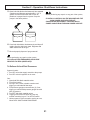
9. &KHFNDQGOXEHWRSRIWKHÀXLGVHFWLRQ
2. 8VHDVXLWDEOHVROYHQWWRÀXVKWKHÀXLGFLUFXLWV7R
determine the compatibility of solvents with material
EHLQJXVHG$OZD\VFKHFNZLWKPDWHULDOVXSSOLHU
3. ,QFUHDVHWUDQVIHUSXPSSUHVVXUHXQWLOÀXLG
movement occurs.
Wipe off residual material
and add a tablespoon
of TSL
,IÀXLGPRYHPHQWGRHVNOT occur @ 100 psi
(0.7 MPa, 7 bar) of air on transfer pumps, increase
main pump pressure until the main proportioner
SLOWLY starts cycling.
4. 2QFHSULPDU\PDWHULDOLVÀXVKHGIURPWKHV\VWHP
UHGXFHWKHPDLQDLUSUHVVXUHWR]HURRUÀLSWKH
retract switch to the “retract position” and trigger
the gun until the pumps are in the down position.
5. ,IWKHVROYHQWXVHGWRÀXVKWKHV\VWHPDOVRFRQWDLQV
SODFWLFL]HUHQVXUHWKDWDOOSULPDU\PDWHULDOLVÀXVKHG
from the system and close the ball valves at the gun.
6. /HDYHWKHSXPSVLQWKHIXOOGRZQVWURNHSRVLWLRQZLWK
'RQRWEOHHGÀXLGSUHVVXUHIURPWKHV\VWHP
approximately 200-500 psi. (1.4-3.4 MPa, 14-35 bar)
RQWKHÀXLGJDXJHV
7. If plasticizer is required to chase out solvent, cycle
Extended Shut-Down Procedure
The following procedure is for long extended shut-down
periods.
main pumps until the system is full of plasticizer, then
close valves and leave the pumps in the full down
VWURNHSRVLWLRQZLWKSVL03D
bar).
Power should be disconnected and all air regulators
turned down to zero.
1.5HPRYHVLGHEORFNVIURPWKHJXQDQGUHOLHYHSUHVVXUH
from the system.
PROBLER P2
19
Section 2 - Operation: Shut-Down Instructions
8. Turn off main air supply and disconnect air line from
2. $GMXVWPDLQDLUUHJXODWRUWRSVL
the system.
3. $GMXVWWUDQVIHUSXPSUHJXODWRUVWRDSSUR[LPDWHO\SVL
9. Generously coat the exposed transfer pump shafts
with lithium grease.
10. Coil the heated hoses with a minimum four foot
GLDPHWHUWRDYRLGNLQNLQJDQGVXEVHTXHQWGDPDJH
to the internal electrical wiring.
11. For gun shut down, follow the procedure from the
gun manual.
12. The length of time a system is shut down, and the
climate conditions it’s stored in will determine how
RIWHQWKHV\VWHPVKRXOGEHSXUJHGDQGUH¿OOHG
8VXDOO\HYHU\ZHHNVWKHIROORZLQJSURFHGXUH
should be followed.
4. 5HPRYHWKHVLGHEORFNVIURPWKHJXQ
3XUJHDQG5H¿OO3URFHGXUH
1. Connect the main air line to the system.
PROBLER P2
20
Section 2 - Operation: Shut-Down Instructions
5. 2SHQERWKVLGHEORFNVVLPXOWDQHRXVO\LQWRVHSDUDWH
FRQWDLQHUVDQGGLVSHQVHDSSUR[LPDWHO\
gallons of material from each side or until all
plasticizer is purged from the system. Stop the
pumps in the down position.
Before performing any repairs on any part of the system,
PLACE ALL CONTROLS ON THE MACHINE AND THE
MAIN POWER SOURCE IN THE OFF
POSITION AND DISCONNECT THE ELECTRICAL
POWER CABLE FROM THE MAIN POWER SOURCE!
6. &ORVHERWKVLGHEORFNVVLPXOWDQHRXVO\DQGZLSHRII
UHVLGXHIURPWKHVLGHEORFNVHDOV5HJUHDVHDQG
DWWDFKERWKEORFNVWRWKHJXQ
7. Mix and properly dispose of purge material.
Before performing any repairs on the system,
ALL AIR and FLUID PRESSURES SHOULD BE
RELIEVED TO ZERO (BLEED-OFF)!
To Relieve Air And Fluid Pressures:
System Console:
1. Turn OFF valves that supply material to the pumps.
2. Turn OFF main air regulator on air motor.
Gun:
2SHQERWK6LGHEORFNPDWHULDOYDOYHV
2. Turn ON air switch.
3. Point gun into a clean, suitable container and
WULJJHUJXQXQWLOPDWHULDOÀRZVWRSV
4. Fluid pressure gauges must read zero (0), if not,
WULJJHUJXQXQWLOWKHÀXLGSUHVVXUHJDXJHVGRUHDG
zero (0) pressure.
7XUQ2))VLGHEORFNPDWHULDOYDOYHV
6. Trigger gun several more times to purge any
material remaining in gun. Turn OFF air switch.
7. Unless system is to be returned to service at once,
follow DAILY SHUT-DOWN PROCEDURE
21
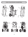
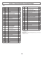
Section 3 - General Information: Assembly Drawings
Guardian A5-6000 Assemblies
22
25
4
41
24
18
18
53
12
52
10
15
52
8
30
4
41
4
41
28
21
14
39
C (32)
31
Included with Control Panel
26
44
40
38
1
39
1
39
43
42
44
40
38
C
(32)
Detail A
Some parts have been removed for clarity
Supplied with cart assembly
See Detail A
Some parts have been removed for clarity
Part
C
# Phases
Voltage
GC1750
GC2440
1
220
GC1752
GC1758
3
220
GC1753
GC1760
3
380
22
Section 3 - General Information: Assembly Drawings
6
6
29
45
29
45
3
41
3
41
20
2
41
23
23
19
29
3
41
3
41
2
41
29
48
Red Tubing
Blue Tubing
51
49
16
50
A
11
B
49
50
54
To A
54
27
27
To B
23
Section 3 - General Information: Assembly Drawings
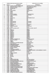
Parts
Ref.
Part
1)
Description
Qty.
RIVET, BLIND
5
10
2
112925
SCREW, CAP
3
GC0433
SCREW
4
4
GC0434
SCREW
12
6
GC0578
ELBOW, JIC;
1370;81)6
8
GC0586
LABEL, TRANSFORMER
GC0797
LABEL, LIVE WIRE
1
11
GC0811
CONNECTOR
1
12S
15G280
LABEL, WARNING
1
13V
GC0834
14)
HOSE, ASSY, THERMOCOUPLE
1
SCREW, SELF-TAP; 2 IN., #10
4
31
CONTROL, PANEL; SEE CONTROL
PANEL ASSY. PAGE
1
32
MODULE, ELECTRICAL; SEE
ELECTRICAL ASSY. PAGE
1
GC2052
39)
1
10S
Description
38
2
WIRE, #6 THHN, BLK; 7.0830 FT.
7)
Ref. Part
Qty.
WASHER, FLAT
4
WASHER, FLAT
9
40
GC2107
WASHER, LOCK, SPRING
4
41
GC2109
WASHER, LOCK, SPRING
26
42
GC2112
WASHER, LOCK, SPRING
2
43
GC2175
SCREW
2
44
GC2192
SCREW
4
45
GC2203
FITTING
2
HOSE, P.E., 0.500OD NATURAL;
1.4 FT.
48)
15
GC1071
SWITCH, POWER
1
49
GC2363
LABEL, ISO
2
16
15W209
JACK, PANEL, CIRCULAR
1
50
GC2364
LABEL ,POLY
2
51
GC2365
LABEL, HOSE
1
52
GC2368
LABEL, MAIN
2
53
GC2369
LABEL, HOSE
1
54
GC0805
SWITCH, PRESSURE, HIGH
2
CONNECTOR, HEATED HOSE
1
CABLE, POWER; 11 FT.
17)V
18
GC1181
GAUGE, PRESSURE,
3000PSI, BACK MT
2
19
GC1714
HEATER, ASSY, HEATER,
DUAL, ROD, ISO
1
20
GC1716
HEATER, HEATER,
DUAL, ROD, POLY, 1500
1
21
GC1718
22
PLATE, BOTTOM
1
CART, ASSY., SEE PG. 29
1
2
23
GC1725
COVER, HEATER
24
GC1726
COVER, SHELL
1
25
GC1730
RING, PANEL, CONTROL
1
26
GC1734
PUMP, ASSY., SEE MANUAL
313277
1
27
GC1744
HOSE, ASSY.
2
NUT, RIVET
4
28)
29
GC1746
WASHER, FIBER
4
30
GC1755
LABEL
1
55V 261821
)Purchase locally.
VNot Shown.
SReplacement Danger and Warning labels, tags, and cards are
available at no cost.
24
Section 3 - General Information: Assembly Drawings
25
Section 3 - General Information: Assembly Drawings
26
Section 3 - General Information: Assembly Drawings
27
Section 3 - General Information: Assembly Drawings
28
Section 3 - General Information: Sub Assembly Drawings
Cart Assembly
125
144
118
142
141
106
102
115
116
117
123
126
106
122
141
101
141
110
106
137
135
119
149
150
105
120
113
119
Some Parts Removed For Clarity
124
147
129
148
130
109
147
129
114
114
147
129
147
129
133
146
138
140
104
104
132
111
132
103
134
144
See Detail A
142
109
139
112
Some Parts Removed For Clarity
145
136
143
108
107
Detail A
29
Section 3 - General Information: Sub Assembly Drawings
Cart Assembly
Ref.
Part
Description
Qty.
Ref.
Part
101
GC0012
ELBOW
2
132 )
GROMMET, RUBBER
2
102
GC0148
CONNECTOR
1
133 )
GROMMET, RUBBER
1
103
GC0217
ADAPTER
1
134
GC2044
WASHER, FLAT, STD,
4
GC2045
WASHER, FLAT, FENDER
2
GC2048
WASHER, FLAT, STD
1
WASHER, FLAT, STD
4
Description
Qty.
104
GC0286
HOSE, ASSY
1
135
105
GC0409
SCREW
2
136
106
112925
SCREW
14
1
107
GC0437
SCREW
108
GC0585
TRANSFORMER, TOUCH SAFE
109 )
RETAINER,PLUG, VENT,
RETAINER
7
137 )
138
GC2052
WASHER, FLAT, STD
4
139
GC2096
187+(;67'
4
140
GC2107
WASHER, LOCK, SPRING
5
141
GC2109
WASHER, LOCK, SPRING
14
110
GC0790
HOSE, ASSY
2
142
GC2110
WASHER, LOCK, SPRING
6
111
GC0999
75$16)250(5%2;
CONTROL
1
143
GC2119
SCREW
1
144
GC2180
SCREW
6
SCREW
4
112
GC1040
CONNECTOR
1
113
GC1042
AMMETER, 30A
1
114
15W209
JACK, PANEL, CIRCULAR
2
115
GC1612
PLATE, COUPLING
1
116
GC1621
LIGHT, PILOT
1
117
GC1625
LIGHT, LED, WHITE, 240V
1
118
GC1719
HANGER, PANEL, CONTROL
2
119
GC1723
COVER, HEATER
2
120
GC1724
BRACKET, AMMETER
1
122
GC1738
FITTING, BULKHEAD
2
123
GC1739
NUT, BULKHEAD
2
124
GC1743
WHEEL
2
GC0020
FITTING
3
125
GC1749
MANIFOLD, ASSY, AIR
1
GC0222
REGULATOR, AIR
2
126
GC1754
MANIFOLD, ASSY, FLUID
1
GC0240
GAUGE, AIR
2
129
GC1999
NUT, CONDUIT
4
GC0241
GAUGE, AIR
1
NUT, CONDUIT
1
)
ELBOW
1
GC0755
VALVE, BALL
1
GC1720
BRACKET, L
1
GC1732
MAINFOLD, AIR
1
GC0000
CAP, OILER
2
130 )
145 )
146
GC2192
SCREW
4
147
GC2372
GRIP, CORD
4
CONNECTOR
1
148 )
149
117455
),77,1*-,&[137
1
150
GC2207
),77,1*-,&[137
1
)Purchase locally.
Part
30
Description
Qty.
GC0001
GASKET, CAP, OILER
4
GC1994
ELBOW
1
GC2016
FITTING, PIPE, TEE
1
GC2110
WASHER, LOCK, SPRING
2
GC2167
1,33/(3,3(+(;
2
GC2169
1,33/(3,3(+(;
2
GC2170
1,33/(3,3(+(;
1
GC2179
SCREW
2
GC1772
LABEL, MANIFOLD
1
Section 3 - General Information: Sub Assembly Drawings
Control Panel Assembly
228
225
221
218
223
220
204
201
227
226
217
220
224
222
228
227
220
219
209
214
215
236
205
210
213
203
212
202
Ref.
Part
Description
201
GC0584
202
203
204
208
Qty.
Ref.
Part
Description
COUNTER, LCD
1
221
GC1614
LENS, ILLUMINATED, "R"
GC0599
)86($03
3
222
GC1616
/(16,//80,1$7(',2
2
GC0601
FUSE, 2AMP
1
223
GC1617
LENS, YELLOW
3
15W684
MODULE, HEATER, CONTROL
2
224
GC1619
LENS, GREEN
2
225
GC1622
LED, YELLOW, 24V
3
4
226
GC1624
LED, GREEN, 24V
2
227
GC1626
BLOCK, CONTACT, NORMALLY
OPEN
5
228
GC1627
BLOCK, CONTACT, NORMALLY
CLOSE
5
230
GC1779
CABLE, PLUG, ELEC., FEMALE
2
RAIL, DIN; 0.875
205 )
3
208
GC0859
FUSE, FUSEHOLDER, DIN RAIL
209
GC0956
LABEL, EMERGENCY STOP
1
210
GC0972
BLOCK, JUMPER, TERMINAL
2
212
GC1161
RELAY, 3 POLE 10AMP
4
213
GC1164
SOCKET, RELAY, 3 POLE,
10AMP
4
214
GC1172
7(50,1$/,1287
6
231
GC1780
CABLE, PLUG, ELEC.,FEMALE
1
215
GC1173
COVER, END, TERMINAL, 2 in.,
2 OUT
3
232
GC1782
CABLE, PLUG, ELECTRICAL,
MALE
2
217
GC1608
BUTTON, LATCHED
2
233
GC1783
1
218
GC1609
BUTTON, MOMENTARY
3
CABLE, PLUG, ELECTRICAL,
MALE
219
GC1611
BUTTON, EMERGENCY STOP
1
236
15W687
MODULE, HOSE CONTROL
1
220
GC1612
PLATE, COUPLING
6
)Purchase locally.
31
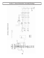
Section 3 - General Information: Sub Assembly Drawings
GC2440 (220V, 1 Phase) Electrical Assembly
313
314
309
314
308
307
302
312
306
305
302
301
303
311
314
314
310
303
315
316
317
Ref.
Part
Description
301
GC0601
FUSE, 2AMP
Qty.
2
RAIL, DIN; 2.4
302 )
303
GC0851
CIRCUIT BRKR, DIN RAIL
3
305
GC0859
FUSE, FUSEHOLDER, DIN RAIL
2
306
GC0974
BLOCKFUSE, 63AMPS
1
307
GC1000
FUSE, 63AMP, TAB, BOLTED
1
308
GC1014
RELAY, SOLID STATE, 63A
1
309
GC1015
RELAY, SOLID STATE, 50A
2
310
GC1055
6:,7&+212))32/(6
1
311
GC1060
&29(5%/2&.6:,7&+212))
1
312
GC1088
RELAY, CONTACTOR,
MECHANICAL, 25A
1
313
GC1262
RELAY, CONTACTOR,
MECHANICAL, 4-POLE
1
314
GC1651
CLAMP, END, TERMINAL,
UNIVERSAL
4
315
GC1030
BLOCK, TERMINAL
2
316
GC1033
SPACER, BLOCK, TERMINAL
4
317
GC1036
COVER, BLOCK, TERMINAL
2
)Purchase locally.
32
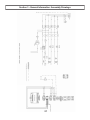
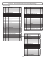
Section 3 - General Information: Sub Assembly Drawings
GC1758 (220V, 3 Phase) Electrical Assembly
313
309
314
314
308
302
307
306
305
312
301
303
302
311
314
314
310
302
303
Ref.
Part
Description
301
GC0601
FUSE, 2AMP
Qty.
2
RAIL, DIN; 2.4
302 )
303
GC0851
CIRCUIT BRKR, DIN RAIL
3
305
GC0859
FUSE, FUSEHOLDER, DIN RAIL
2
306
GC0974
BLOCKFUSE, 63AMPS
1
307
GC1000
FUSE, 63AMP, TAB, BOLTED
1
308
GC1014
RELAY, SOLID STATE, 63A
1
309
GC1015
RELAY, SOLID STATE, 50A
2
310
GC1055
6:,7&+212))32/(6
1
311
GC1060
&29(5%/2&.6:,7&+212))
1
312
GC1088
RELAY, CONTACTOR,
MECHANICAL, 25A
1
313
GC1262
RELAY, CONTACTOR,
MECHANICAL, 4-POLE
1
314
GC1651
CLAMP, END, TERMINAL,
UNIVERSAL
4
)Purchase locally.
33
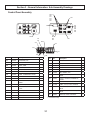
Section 3 - General Information: Sub Assembly Drawings
GC1760 (220V, 3 Phase) Electrical Assembly
415
414
414
408
402
416
407
402
405
406
401
403
414
414
404
412
413
403
402
409
410
411
Ref.
Part
Description
401
GC0601
FUSE, 2AMP
Qty.
Ref.
Part
Description
2
409
GC1030
BLOCK, TERMINAL, CURRENT,
HIGH
1
410
GC1033
SPACER, BLOCK, TERM,
CURRENT, HIGH
2
RAIL, DIN, 2.4
402 )
Qty.
403
GC0851
CIRCUIT BRKR, DIN RAIL
3
404
GC0859
FUSE, FUSEHOLDER, DIN
RAIL
2
411
GC1036
COVER, BLOCK, TERM,
CURRENT, HIGH
1
405
GC0974
BLOCK, FUSE, 63AMPS
1
412
GC1056
6:,7&+212))32/(6
1
406
GC1000
FUSE, 63AMP, TAB, BOLTED
1
413
GC1061
GC1014
RELAY, SOLID STATE, 63A
1
&29(5%/2&.6:,7&+21
OFF, 4POL
1
407
408
GC1015
RELAY, SOLID STATE, 50A
2
414
GC1651
CLAMP, END, TERMINAL,
UNIVERSAL
4
415
GC1262
RELAY, CONTACTOR,
MECHANICAL, 4-POLE
1
416
GC1088
RELAY, CONTACTOR,
MECHANICAL,25A
1
)Purchase locally.
34
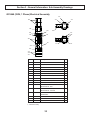
Section 3 - General Information: Sub Assembly Drawings
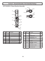
GC1714, GC1715, GC1716, GC1717 Heat Exchanger Assembly
517,
518
509
505
502
503
501
507
502
504, 516
511
510
508
506
517, 518
Ref.
Part
Description
Qty.
ISO MODEL
506
WATTS
Qty.
501
GC0025
PLUG, PIPE
1
GC1714
GC0891
1500
2
502
GC1748
.,725,1*NLWLQFOXGHV
4
GC1715
GC0893
750
2
503
GC0482
CONNECTOR
1
504
GC0554
SCREW
4
505
GC0559
THERMOMETER, THERMOCOUPLE,
VELOCITY, HIGH
1
POLY
MODEL
506
WATTS
Qty.
ELEMENT, HEATER; SEE TABLES
2
GC1716
GC0891
1500
2
SWITCH, OVERTEMP
2
GC1717
GC0893
750
2
506
507
GC0962
508
GC1226
SPRING, COMPRESSION,
2
509
GC1711
CAP, FRONT, HEATER, DUAL
1
510
GC1712
CAP, REAR, HEATER, DUAL
1
511
GC1713
+286,1*%2'<(;758'('+($7(5
1
512 V
GC1773
CABLE, PLUG, ELEC., FEMALE
1
513 V
GC1774
CABLE, PLUG, ELEC., MALE
1
514 V
GC1778
CABLE, PLUG, ELEC., FEMALE
1
515 V
GC1781
CABLE, PLUG, ELEC., MALE,
1
516
GC2105
WASHER, LOCK, SPRING
4
517
GC2109
WASHER, LOCK, SPRING
12
518
GC2151
SCREW
12
VNot Shown.
35
Section 3 - General Information: Maintenance
Daily Routine Maintenance
1. 9LVXDOO\LQVSHFWWKHV\VWHPIRUOHDNV
2. &KHFNGHVLFFDQWGU\HUWRHQVXUHSURSHUIXQFWLRQLQJ
Replace dryer beads as necessary.
3. &KHFNDQGOXEHWRSRIWKHÀXLGVHFWLRQ
Wipe off residual material
and add a tablespoon
of TSL
Weekly Maintenance
1. Place a small amount of grease on the air motor
shaft.
2. See related manuals.
36
Section 3 - General Information: Troubleshooting
If a high pressure situation develops, the sensor will detect
this and immediately engage the hold-in circuit.
Do not place any part of the body in the path of the
material spray.
Do not point the gun at or near other personnel.
'RQRWORRNLQWRWKH0L[LQJ&KDPEHURUL¿FHDWDQ\
time.
Because of the hazardous materials used in this
equipment, it is recommended that the operator
use an air mask, goggles, protective clothing, and
other safety equipment as prescribed by current
regulations, recommendations of the chemical sup
pliers, and the laws in the area where the equip
ment is being used.
This will disengage power to the air motor and will also
turn the heaters off.
On the control box panel, there are three yellow lighted push
EXWWRQVPDUNHGRYHUSUHVVXUH2QHRIWKHVHSXVKEXWWRQV
will be illuminated after the monitoring sensor engages, indicating where the problem is located
(ISO, Poly, or Hose).
The system will dispense liquid at high pressure
when Gun Trigger is activated. Read and note
WARNINGS contained in this User Manual and
the Probler P2 Gun User Manual, 313213.
The Polyol will expand in the Hose if any normal
operating pressures are bled off whenever the material is above approximately 75 degrees F. Hot Polyol
hoses should never be bled, by any method, to zero
pressure for two reasons.
1. The seals in the Gun rely on high pressure to make
their seal. The high pressure cannot be maintained if
the pumps are attempting to apply this pressure
through a hose full of expanded froth; therefore, the
Gun seal may leak.
2. Re-starting immediately after hot Polyol has expanded in the system may result in spraying substantial amounts of “bad” foam. This will continue until the expanded Polyol in the primary Heater and the
Hose has been completely purged.
In the over pressure situation, the system will remain shutdown until it is manually reset.
At this point, it is necessary to determine if the problem is an
over pressure situation.
When the sensor engages, the system will be frozen, giving you the pressure readings at the time the problem was
detected.
,QVSHFWWKHÀXLGSUHVVXUHJDXJHVLQDQRYHUSUHVVXUHVLWXDWLRQRQHRIWKHÀXLGSUHVVXUHJDXJHVZLOOEHVLJQL¿FDQWO\
higher than the other gauge.
Over Pressure System Protection
The system incorporates monitors for high
pressure monitoring. These monitoring devices will
prevent the system from continued operation if
high pressure situations develop.
There are pressure sensors located on each propor
tioning pump. The high pressure sensor is located at
WKHRXWERXQGRIWKHÀXLGVHFWLRQ
When main power to unit is on, the console will have wires
that are live. Disconnect or turn off main power source before opening console to make any repairs.
Before performing any repairs on the system,
ALL AIR and FLUID PRESSURES SHOULD BE RELIEVED
TO ZERO (BLEED-OFF)!
The high pressure monitoring sensor will engage if
ÀXLGSUHVVXUHLQFUHDVHVDERYHSVL
37
Section 3 - General Information: Troubleshooting
Over Pressure Problem Correction
Material Or Mechanical Problem
1. Determine if the problem is high pressure related.
Troubleshooting Procedure
2. Relieve system material pressure.
By following this procedure, you should be able to locate
and cure problems easily. Remember, however, that a
VXFFHVVIXORSHUDWRUPXVWNQRZ
3. Turn off main power.
:+$7*22'0$7(5,$//22.6/,.(
4. Fix the problem area:
+2:7+((48,30(171250$//<23(5$7(6
a. Potential high pressure causes:
-Restriction
-Overheating material in static position
,62¿OWHUDWJXQ
:+$73$7+7+(0$7(5,$/6)2//2:7+528*+
THE EQUIPMENT.
.12:/('*(2)7+(6(7528%/(6+227,1*
PROCEDURES.
5. Re-start system for operation
Always start with step one, never skip any portion of
these procedures. The material pressure gauges are to
be used for troubleshooting purposes only. The
pressures registered on one gauge will not necessarily
match the other. This difference can be caused by
variance in materials, temperatures, viscosities, etc.
Once the power has been turned off and problem
solved, and the main power is turned on again, the
over pressure lighted buttons will automatically be
reset.
If you do not understand the electrical hook-up de
scribed above, consult your local GlasCraft distributor
25DTXDOL¿HGHOHFWULFLDQ
1. Identify the missing material.
2.&KHFNWKHPDWHULDOSUHVVXUHJDXJHRQWKH
missing material side.
,WLVUHFRPPHQGHGWKDWDTXDOL¿HGOLFHQVHGHOHFWULFLDQ
should install power to the supply disconnect.
a. If the missing material gauge reads HIGHER than
normal, there is a RESTRICTION problem
between the gauge and the Mixing Chamber tip
in the Gun.
You should always follow all local or national electrical
codes.
Disconnect power source BEFORE attempting any repairs or opening the Control Boxes. Access to internal
SDUWVLVOLPLWHGWRTXDOL¿HGSHUVRQQHO21/<
Place Main Power Switch in OFF position BEFORE disconnecting power cables. This equipment is not
approved for use in hazardous locations as set forth in
the National Electrical Code Article 500 and Sub-Part “S”
of the OSHA Standards.
b. If the missing material gauge reads LOWER than
normal, there is a STARVATION problem between
the gauge and the material supply system.
3UREOHPVPD\EHF\FOLFLQWKDWWKH\ZLOODSSHDU¿UVWRQ
only one stroke of the Proportioning Pump. Check the
pressure gauges during one of these bursts of missing
materials and always stop spraying while you are
getting a burst of good material.
3. Concern yourself only with the material pressure
on the missing material side. In troubleshooting a
STARVATION problem where the pressure gauge
on the missing material side is LOWER than normal,
VWDUWDWWKHSRLQWIDUWKHVWIURPWKHXQLWDQGZRUN
IRUZDUG&KHFNWKHREYLRXVDQGHDV\WKLQJV¿UVW
38
Section 3 - General Information: Troubleshooting
A. MATERIAL DRUMS
1. Material in drums?
2. Material temperature?
a. If the material is too cold, especially at the
bottom of the drum, it will raise the viscosity of
the material and stall Transfer Pumps.
A. GUN
6LGHEORFNPDWHULDOYDOYHWXUQHGRQ"
2. Bore hole of mixing chamber clean?
3. Filter strainer screen clean?
4. Side hole in mixing chamber clean?
B. MATERIAL TEMPERATURE
B. OPTIONAL TRANSFER PUMP(S)
1. Too high a temperature on resin side can cause
1. Is it operating?
a blowing agent to pre-expand in either the
2. Is air turned on to transfer pump?
hose or the primary heater.
3. Regulated pressure where it should be?
4. Severe contamination of pump shaft on isocyaC. HOSES
nate side. This indicates that the pump shaft is not
0DNHVXUHWKDWWKH+RVHVDUHQRWSOXJJHG
being lubricated.
&KHFN)LOWHURIWUDQVIHUSXPS
TROUBLESHOOTING A POOR SPRAY PATTERN
6. Before diagnosing a faulty transfer pump, be sure
DQGFKHFNDOOLWHPVMXVWOLVWHGXQGHU7UDQVIHU3XPS
To troubleshoot a poor spray pattern, you must
understand the factors that affect the spray pattern.
C. FILTER ASSEMBLY
&KHFNÀXLG¿OWHUDWLQOHWWRSURSRUWLRQLQJSXPSV
if applicable.
A. TEMPERATURE
1. Too warm a material temperature will cause a
D. PROPORTIONING PUMPS
VHSDUDWLRQ¿QJHULQJLQWKHSDWWHUQ
1. Determine whether the burst appears on the
2. Too cold a material temperature will cause a
3XPS¶VXSRUGRZQVWURNH
stream effect.
D,IEXUVWDSSHDUVRQ83VWURNHFKHFN833(5
ball Seat and cups.
E,IEXUVWDSSHDUVRQ'2:1VWURNHFKHFN
B. PRESSURE
LOWER Ball Seat
1. Too high a pressure will cause excessive
Follow the procedures in the order given. Remember
that repairs should be made as soon as possible.
Don’t leave the unit open to air any longer than
necessary, as this will lead to further problems, such
as moisture entering the system and causing the
isocyanate to crystallize.
RYHUVSUD\DQGRUVHSDUDWLRQ¿QJHULQJ
2. Too low a pressure will cause a stream effect.
C.&217$0,1$7,21,17+(0,;,1*&+$0%(5
$IRUHLJQREMHFWLQWKHPL[LQJFKDPEHUZLOO
cause a poor pattern.
Correct problem(s) immediately!
After the unit has been exposed to the atmosphere, it
should be run long enough to displace the material that
was in the unit when it was opened up.
1(9(5LQVSHFW¿OWHUDVVHPEOLHVDWWLPHRIVKXWGRZQ
4. In troubleshooting, a restriction problem where the
material pressure gauge on the missing material
side is higher than normal, start at the point farthest
IURPWKHXQLWDQGZRUNEDFNZDUG&KHFNREYLRXV
DQGHDV\WKLQJV¿UVW
Before performing any repairs on the gun, ALL AIR and
FLUID PRESSURES SHOULD BE RELIEVED TO
ZERO (BLEED-OFF)!
39
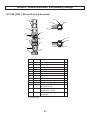
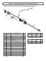
Section 3 - General Information: Options
GC0174 Transfer Kit (supplied with unit)
GC1240
GC1233
GC0479
GC0178
GC1747
GC2208
GC2199
Transfer Pump;
purchase separately
7KHWUDQVIHUNLWDWWDFKHVWKHVDPHZD\IRUERWK
ISO & POLY side. Use PTFE tape on NPT threads.
40
Section 4 - Warranty and Reference Information: Limited Warranty Policy
Graco Standard Warranty
Graco warrants all equipment referenced in this document which is manufactured by Graco and bearing its name to be free
IURPGHIHFWVLQPDWHULDODQGZRUNPDQVKLSRQWKHGDWHRIVDOHWRWKHRULJLQDOSXUFKDVHUIRUXVH:LWKWKHH[FHSWLRQRIDQ\
special, extended, or limited warranty published by Graco, Graco will, for a period of twelve months from the date of sale,
repair or replace any part of the equipment determined by Graco to be defective. This warranty applies only when the equipment is installed, operated and maintained in accordance with Graco’s written recommendations.
This warranty does not cover, and Graco shall not be liable for general wear and tear, or any malfunction, damage or wear
caused by faulty installation, misapplication, abrasion, corrosion, inadequate or improper maintenance, negligence, accident, tampering, or substitution of non-Graco component parts. Nor shall Graco be liable for malfunction, damage or wear
caused by the incompatibility of Graco equipment with structures, accessories, equipment or materials not supplied by
Graco, or the improper design, manufacture, installation, operation or maintenance of structures, accessories, equipment
or materials not supplied by Graco.
This warranty is conditioned upon the prepaid return of the equipment claimed to be defective to an authorized Graco disWULEXWRUIRUYHUL¿FDWLRQRIWKHFODLPHGGHIHFW,IWKHFODLPHGGHIHFWLVYHUL¿HG*UDFRZLOOUHSDLURUUHSODFHIUHHRIFKDUJHDQ\
defective parts. The equipment will be returned to the original purchaser transportation prepaid. If inspection of the equipPHQWGRHVQRWGLVFORVHDQ\GHIHFWLQPDWHULDORUZRUNPDQVKLSUHSDLUVZLOOEHPDGHDWDUHDVRQDEOHFKDUJHZKLFKFKDUJHV
may include the costs of parts, labor, and transportation.
THIS WARRANTY IS EXCLUSIVE, AND IS IN LIEU OF ANY OTHER WARRANTIES, EXPRESS OR IMPLIED, INCLUDING BUT NOT LIMITED TO WARRANTY OF MERCHANTABILITY OR WARRANTY OF FITNESS FOR A PARTICULAR
PURPOSE.
Graco’s sole obligation and buyer’s sole remedy for any breach of warranty shall be as set forth above. The buyer agrees
WKDWQRRWKHUUHPHG\LQFOXGLQJEXWQRWOLPLWHGWRLQFLGHQWDORUFRQVHTXHQWLDOGDPDJHVIRUORVWSUR¿WVORVWVDOHVLQMXU\WR
person or property, or any other incidental or consequential loss) shall be available. Any action for breach of warranty must
be brought within two (2) years of the date of sale.
GRACO MAKES NO WARRANTY, AND DISCLAIMS ALL IMPLIED WARRANTIES OF MERCHANTABILITY AND FITNESS FOR A PARTICULAR PURPOSE, IN CONNECTION WITH ACCESSORIES, EQUIPMENT, MATERIALS OR COMPONENTS SOLD BUT NOT MANUFACTURED BY GRACO. These items sold, but not manufactured by Graco (such as
HOHFWULFPRWRUVVZLWFKHVKRVHHWFDUHVXEMHFWWRWKHZDUUDQW\LIDQ\RIWKHLUPDQXIDFWXUHU*UDFRZLOOSURYLGHSXUFKDVHU
ZLWKUHDVRQDEOHDVVLVWDQFHLQPDNLQJDQ\FODLPIRUEUHDFKRIWKHVHZDUUDQWLHV
In no event will Graco be liable for indirect, incidental, special or consequential damages resulting from Graco supplying
equipment hereunder, or the furnishing, performance, or use of any products or other goods sold hereto, whether due to a
breach of contract, breach of warranty, the negligence of Graco, or otherwise.
FOR GRACO CANADA CUSTOMERS
7KH3DUWLHVDFNQRZOHGJHWKDWWKH\KDYHUHTXLUHGWKDWWKHSUHVHQWGRFXPHQWDVZHOODVDOOGRFXPHQWVQRWLFHVDQGOHJDO
proceedings entered into, given or instituted pursuant hereto or relating directly or indirectly hereto, be drawn up in English.
Les parties reconnaissent avoir convenu que la rédaction du présente document sera en Anglais, ainsi que tous documents,
DYLVHWSURFpGXUHVMXGLFLDLUHVH[pFXWpVGRQQpVRXLQWHQWpVjODVXLWHGHRXHQUDSSRUWGLUHFWHPHQWRXLQGLUHFWHPHQWDYHF
les procédures concernées.
Graco Information
TO PLACE AN ORDER, contact your Graco distributor or call to identify the nearest distributor.
Phone: 612-623-6921 or Toll Free: 1-800-328-0211 Fax: 612-378-3505
PARA EFETUAR ENCOMENDAS OU PARA ASSISTÊNCIA TÉCNICA, contate o seu distribuidor da Graco.
POUR PLACER UNE COMMANDE OU DEMANDER DU SERVICE, contactez votre distributeur Graco.
PARA REMITIR UN PEDIDO O SOLICITAR SERVICIO, póngase en contacto con el distribuidor de Graco.
41
Section 4 - Warranty and Reference Information: Technical Assistance
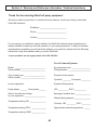
Thank You for selecting GlasCraft spray equipment
Should you have any questions or need technical assistance, contact your factory authorized
GlasCraft distributor.
'LVWULEXWRUBBBBBBBBBBBBBBBBBBBBBBBBB
3KRQHBBBBBBBBBBBBBBBBBBBBBBBBBBBB
&RQWDFWBBBBBBBBBBBBBBBBBBBBBBBBBBB
For any issues your distributor cannot address, the GlasCraft technical service department is
always available to assist you with the operation of your spray equipment. To help our technical
representatives expedite your call and better address your questions, please have the following
information ready and available when you phone GlasCraft.
* If your questions are not urgent, please call 1-800-328-0211.
For Air Powered Systems:
Model: _____________________________
Serial number: _______________________
Air compressor size: __________________
CFM generated: _____________________
Type of spray gun: ____________________
Serial number: _______________________
Pressure at the system:
Hydraulic ________ Pneumatic _________
,V\RXUHTXLSPHQW'\QDPLFÀXLGSUHVVXUH
Single phase: _______ Three phase ______
ISO __________ POLY ___________
What is the inbound voltage
to your equipment: ____________________
Spray gun chamber size: ______________
Material being sprayed: _______________
Temperature setting ISO: _______________
Viscosity: ISO _________ POLY ________
Temperature setting POLY: ______________
Approximate material temperature: ______
Temperature setting HOSE: _____________
42
For Your Reference
Date Purchased
__________________________________________________
Distributor
______________________________________________________
______________________________________________________
Contact
______________________________________________________
Phone
______________________________________________________
E-mail
______________________________________________________
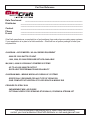
GlasCraft manufactures a complete line of polyurethane foam and polyurea coating spray systems.
,I\RXUDSSOLFDWLRQLVLQSODQWRUD¿HOGFRQWUDFWRU*ODV&UDIWKDVDV\VWHPSDFNDJHWRPHHW\RXU
requirements.
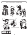
GUARDIAN - AIR POWERED / A5 & A6 SERIES EQUIPMENT
. 6000 OR 12000 WATTS OF HEAT
. 1600, 2200, OR 3000 PRESSURE SET-UPS AVAILABLE
MH, MH II, & MH III HYDRAULIC POWERED SYSTEMS
. UP TO 45 LBS / MINUTE OUTPUT
. EXCELLENT PERFORMANCE AND RELIABILITY
GUARDIAN MMH - MOBILE MODULAR HYDRAULIC SYSTEMS
. SPECIFICALLY DESIGNED FOR ANY TYPE OF SPRAY RIG
. GIVE COMPLETE UTILIZATION OF FLOOR SPACE IN MOBILE RIG
PROBLER P2 SPRAY GUN
. IMPINGEMENT MIX / AIR PURGE
. OPTIONAL NOZZLE FOR SPRAYING STUD WALLS, POURING & STREAM JET
For more information concerning any of these GlasCraft products,
contact your local authorized GlasCraft distributor or visit www.glascraft.com
Quality
a tty
y and
an
nd Performanc
Performance…
er rm nc …
GENUINE
N
G
GL
GLA
GLASCRAFT
L
LA
T
www.glascraft.com
313268B
GRACO INC.
P.O. BOX 1441
MINNEAPOLIS, MN 55440-1441
Phone
Toll Free
Fax
612-623-6921
1-800-328-0211
612-378-3505