1
User’s Manual
3.7.18
3.7.19
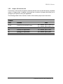
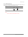
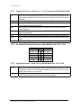
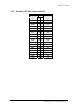
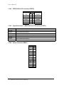
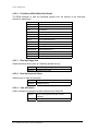
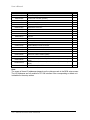
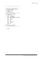
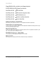
CD-ROM Audio Input Connector (CN8)
Signal
PIN
CD_GND
1
CD_L
2
CD_GND
3
CD_R
4
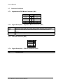
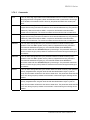
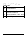
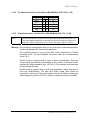
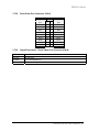
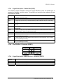
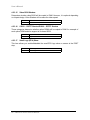
Signal Description – CD-ROM Input Connector (CN8)
CD L/R
Left and right CD audio input lines.
CD_GND
GND for left and right CD. This GND level is not connected to the board GND.
3.7.20
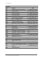
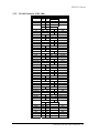
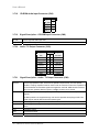
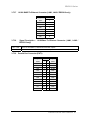
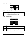
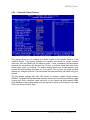
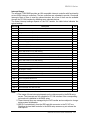
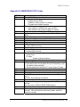
Audio / TV Output Connector (CN9)
Signal
3.7.21
PIN
Signal
Mic
1
2
Mic Bias
AGND
3
4
AGND
Line-Out L
5
6
Line-Out R
SPK L
7
8
SPK R
Line-In L
9
10
Line-In R
AGND
11
12
Yout
GND
13
14
Cout
GND
15
16
COMP
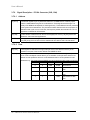
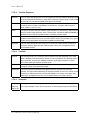
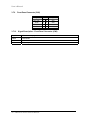
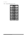
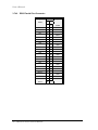
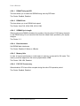
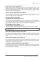
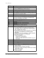
Signal Description – Audio / TV Output Connector (CN9)
SPK L/R
Left and right speaker output. These are the speaker outputs directly from the speaker
amplifier. Coupling capacitors must be used in order to avoid DC-currents in the speakers. If
the Audio Bracket is used these signals are supplied on the PCB. GND should be used as
return for each speaker. Maximum power: 0.5W@4 Ω load for each channel.
Mic / Mic Bias
The MIC signal is used for microphone input. This input is fed to the left microphone
channel.
Mic Bias provides 3.3V supplied through 3.2K Ω with capacitive decoupling to GND. This
signal may be used for bias of some microphone types.
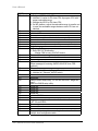
Line-In L/R
Left and right line in signals.
Line-Out L/R
Left and right line out signals. Both signals are capacitor coupled and should have GND as
return.
Yout
Luminance output
Cout
Chrominance output
COMP
Composit video output
36 EBC5612 Series User’s Manual