1
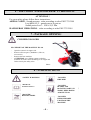
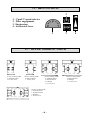
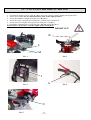
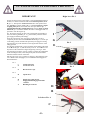
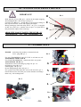
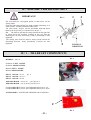
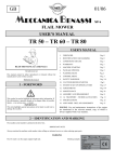
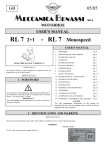
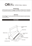
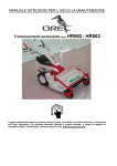
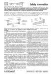
03/05
GB
MOTORHOE RT 401
Gasoline engine
USER’S MANUAL
INDEX
READ THIS MANUAL CAREFULLY
All right reserved
This manual cannot be either reproduced or released without the
manufacturer’s prior written consent.
PRINTED IN ITALY
1 - FOREWORD
This symbol is used to highlight an important safety information.
If this information is ignored, people are in danger either of
possible injures – even serious ones – or death.
1.
FOREWORD
Pag. 0
2.
IDENTIFICATION AND MARKING
Pag. 0
3.
CONDITIONS-USE
Pag. 1
4.
WARRANTY
Pag. 1
5.
SAFETY WARNINGS
6.
NOISE AND VIBRATIONS
Pag. 4
7.
PACKAGE OPENING
Pag. 4
8.
WARNING SIGNS
Pag. 4
9.
TECHNICAL FEATURES
Pag. 5
Pag. 2-3
10. TECHNICAL DATA
Pag. 5
11. DRIVING SIGNS
Pag. 6
12. TILLER WORKING WIDHT
Pag. 6
13 CAUTIONS BEFORE STARTING
Pag. 7
14 MACHINE STARTING
Pag. 8
15 ADJUSTMENTS
Pag. 9
16 ENGINE SAFETY DEVICE
Pag. 10
17 LUBRICANTS
Pag. 10
18-18/1 TILLER SET
Pag. 11
19
Pag. 12
DECLARATION OF CONFORMITY
IMPORTANT
This term highlights special precautions to be taken in order not
to damage the machine.
ENGINE
Use and maintenance instructions of the engine are
mentioned in the relevant manual, copy of which is always
supplied with every machine.
2 - IDENTIFICATION AND MARKING
The machine serial number is printed on the drive box.
IMPORTANT NOTE
Always mention the machine serial number when calling our technical service or when ordering spare parts.
MARKING
Marking example
The CE mark is on the engine support right side.
.
-0-
3-CONDITIONS AND USE
4-WARRANTY
This manual gives you general information on how this
machine should be used and maintained. For any technical
problem, please, call Your confidential dealer.
•
This machine has been designed to be used in
compliance with what specified in the machine
descriptions and safety warnings of this instructions
manual.
•
Any other use is not allowed. The manufacturer is
not responsible for damages caused by any use then
the intended use. The user is fully responsible for
any possible risk.
•
Use, maintenance and repair clauses prescribed by
the manufacturer are also integral part of the
machine intended use.
•
Only people familiar with this machine and well
aware of its hidden risks can use, repair and
maintain it.
•
The manufacturer is not responsible for damages
caused by non-authorized changes made on this
machine.
•
Besides warnings mentioned in this manual, please,
also comply with general regulations on safety and
accident prevention of EEC and the country in
which this machine will be operating.
If in doubt on causes and possible solutions for a certain
trouble, please, call our authorized dealer.
This should be absolutely done during the warranty
period, since any repair made by non-authorized
workshops makes this warranty null and void.
Bear always in mind that the authorized dealer has all
special tools, technical specifications and spare parts
necessary for properly fixing the machine.
Therefore, he should be called in case of any doubt on
maintenance specifications and/or procedures. Some
pages of this manual might not be perfectly right due to
misprints or production changes. For this reason, call
Your dealer before being perfectly familiar with this
machine and personally maintaining this machine. For
further information on use and maintenance of this
machine, ask your authorized dealer for the proper
technical manuals.
Our materials have a 12 months warranty (coverings and
electrical parts are not included). The manufacturer
agrees on replacing those parts considered as faulty free
of charge. Purchaser will be charged with labour costs –
necessary for repairing the machine – and possible
transport costs. Both the warranty claim and the returned
piece should always be addressed to our Spare Parts
Department and accompanied by regular freight bill
mentioning all the machine details.
As far as materials available on the market – especially
engines – are concerned, regulations of our supplier will
apply and applications for possible technical service
should be addressed to the local specialized technical
service centres.
Descriptions, figures and technical features mentioned
herein are non-binding for the Manufacturer. These are
mentioned as mere information. The Manufacturer
reserves the right to make any change at any time
without being bound to update this publication.
Copyright of MECCANICA BENASSI S.P.A.”
-1-
5- SAFETY WARNINGS
This machine has been designed and manufactured for being used by one operator
only, and is driven by means of the appropriate handlebars. Any other use is not
permitted.!
Before the machine is operating, read the Use and Maintenance manual
thoroughly, so that you are fully aware of all the operating controls and safety
aspects of the machine.
Before starting the engine , be sure that speeds selector is in position “F” and
the SAFETY DEVICES are well working and fitting. Without these cares the
operator might work in a danger situation.
DON’T SABOTAGE THE ENGINE STOP’ SAFETY DEVICE AND THE
DISENGAGEMENT DEVICE. THE MACHINE MIGHT BECOME
EXTREMELY DANGEROUS!
3) Do not under any circumstances transport people or objects on the machine.
4) Always ensure that the machine’s safety devices are correctly mounted and in perfect
working condition..
5) Before use, check that all the controls, in particular the clutch, the Motor stop and the brakes
(if fitted)are in good working order.
6) Any modification or spurious parts being fitted without the Manufacturer consent will nullify
the guarantee, and any possible resulting damage will not answered for.
7) This machine must not be used by children or inexperienced persons.
8) Before operating the machine, check that the area is clear and free of debris and that there are
no people within the working area (danger zone). The operator, will be held responsible for the
safety of third parties, if these are found within the working area of the machine. Do not use the
machine under these conditions.
9) Keep clear of cutting blades at all times while the machine is in operation. Pay particular
attention when reversing; keep hands and feet clear.
10) Use the machine only with the handles in the correct working position. This allows a safe
working distance between the operator and operating area.
11) Use only original accessories and spare parts to guarantee safety and correct operation of the
machine.
12) Stop engine before refuelling and remove ignition key (if fitted).
13) Handle the fuel with care to avoid spilling on the machine; clean any spillage immediately.
14) Never refuel in confined places, in vicinity of open flames or near the source of sparks. No
smoking!
15) Before starting the engine, check that all the controls are in the idle position.
16) Do not smoke when starting the engine!
17) Do not run the machine in a confined area as toxic exhaust gas can kill.
18) Plan your work before commencing.
19) Do not use the machine when you are tired.
-2-
5- SAFETY WARNINGS
20) Engage the clutch gradually; sudden engagement could cause the machine to rear up.
21) The area next to the engine exhaust will most likely reach temperatures above 80°.
Attention! Danger of scalding.
22) Always wear close fitting clothes and anti-slip shoes or boots. For safety reasons avoid
using loose clothing.
23) Make regular checks that all bolts and nuts are well tightened.
24) Keep the area of work clear and clean.
25) Only use the machine in clear visibility.
26) Avoid working with blunt cutting blades.
27) Pay maximum attention and use good sense when operating the machine.
28) If you hit any objects during work, stop the machine and check for any damage
immediately.
29) During movement to and from the area of work, disengage the Power Take Off. (P.T.O).
30) Pay attention when reversing the machine not to trip over anything. If you loose your
balancer, release the handlebars immediately; the Motor stop or the disengagement will
immediately stop the machine.
31) Do not under any circumstance attempt to by-pass the motor-stop device or remove the
disengagement device. The machine would result having no safety precautions and would be
extremely dangerous.
32)Do not travel down hill with the clutch disengaged or the gears in idle.
33) The machine’s speed must always suit the conditions and the environment.
34) Do not perform cleaning or maintenance operations of the machine when the engine is
running.
35) Avoid sharps turns when travelling up hill, down hill or across steep slopes.
36) In steep descents, do not disengage the drive and do not change gear.
37) When possible, avoid working up or down hill .Always travel across the slope.
38) Do not work on very steep slopes (max.30%).
39)Avoid overfilling the fuel tank.
It is important that the working position of the operator is always behind the
handlebar.
40) If there is fuel in the tank, avoid tilting the machine during maintenance or adjustment.
41) During use, keep the hot sections of the engine (i.e. cylinder head, exhaust, etc.) clean to
avoid a build up of debris that will overheat the engine.
42) Whenever possible, stop the machine on level ground.
43) When stopping on unlevelled ground, engage 1stgear (up hill) or reverse gear (down hill).
44) If leaving the machine for a long time, ensure it is inaccessible to children and
inexperienced people. Close the fuel tap (if fitted).
45) Do not leave the machine with the engine running.
46) The maintenance instructions of the machine must always be carefully followed and worn
parts replaced when necessary.
47) If the machine is to remain unused for some time, clean it accurately and insert the
appropriate protections.
48) Apart from the previous items, it is necessary to take heed of the specific safety norms in
force in the Country where the machine is operating.
-3-
6 – AIRY NOISE AND HANDLEBAR ’S VIBRATIONS
ATTENTION !
For your safety please follow these instructions :
AERIAL NOISE: Sound pressure value according to rules EN12733:2001
Leq (dBA) 85,5 – guard-ears to be put on.
Sound power level : LWA 95,5 Dba
HANDLEBAR VIBRATIONS : value according to rules EN12733:2001
7 - PACKAGE OPENING
CRUSHING DANGER
NB: WEIGHT OF THE MACHINE KG. 60.
-
Open the carton in its upper side.
Remove all loose parts (handlebar , tiller set ,
accessories).
Remove the bare machine.
ATTENTION: use a lifting system to take the
machine out of the carton according to its weight and
follow closely the safety rules.
Pic. 1
8 - WARNING SIGNS
“SAFETY WARNINGS”
“DANGER”
FIRE RISK
“READ USE
INSTRUCTIONS “
“DANGER”
BLADES AND
ROTATING PARTS IN
WORK. KEEP HANDS
AND FEET FAR
“DANGER”
BURNING RISKS
“DANGER”
KEEP CHILDREN
FAR FROM THE
MACHINE
-4-
9 – TECHNICAL FEATURES
2
1
12
5
MAIN PARTS:
1.
2.
3.
4.
5.
6.
7.
Accelerator lever
Engine stop lever
Handlebar
Handlebar adjustment lever
Engine starter
Bumper
Fuel tank (see also the engine
manual)
8. Driving wheel
9. Cutter set
10. Cutter hood
11. Clutch lever
12. Cutter disengaging lever
7
3
4
11
10
9
8
6
10 – TECHNICAL DATA
4 Strokes Engine
Recoil starter – transmission to the wheel and to the tiller set by chain and gears –
2 forward speeds – Handlebar adjustable in any position – Air filter in oil bath –
Centrifugal clutch in oil bath -
Pic. 3
-5-
11 – DRIVING SIGNS
2
1.
2.
3.
4.
1*and 2* speed selector
Tiller engagement
Engine stop
Accelerator lever
1
3
4
12 – TILLER WORKING WIDTH
16 cms. working width
2 unilateral knives
1 14 cms. Pivot
24 cms. working width
2 bilateral knives
1 14 cms. Pivot
32 cms. working width
2 unilateral knives
2 bilateral knives
2 bushings
1 31 cms. pivot
50 cms. working width
4 bilateral knives
2 unilateral knives
4 bushings
1 48 cms. pivot
-6-
40 cms. working width
4 bilateral knives
2 bushings
1 31 cms. pivot
13 – CAUTIONS BEFORE STARTING
1. Checking the engine oil level, plug “L” pic. 1; few or no oil may seriously damage the engine itself.
2. Please read carefully the use and maintenance book of the engine producer.
3. Check the handlebar’s height using the lever “B” pic. 2
4. Check the switch : position ON: switched on, position OFF: switched off
5. Use the setscrew “A” pic. 4 for a good work of the lever “I” pic. 3.
6. Check the oil transmission levels by the plug “M” pic. 1 and “N” pic. 5.
ATTENTION: do the above with the engine always switched off.
IMPORTANT!
B
L
M
Pic.2
Pic. 1
I
A
Pic. 3
N
Pic. 5
-7-
Pic. 4
14 – ENGINE START UP AND SAFETY DEVICES
IMPORTANT!
Right lever Pic. 1
Follow the instructions of the engine’s USE and MAINTENANCE
booklet, too and check that the clutch is in neutral position, lever
D (pic. 3). Then put the accelerator lever G in start position and
the switch I in position “ON”( pic. 1 ). Put lever B down , engine
stopping safety lever, and in the same time put lever C up ,
engaging/disengaging rotating tiller lever, then by hook A block
the levers (pic. 4 ). In this situation the tiller is disengaged and it is
possible to start the engine up.
For the engine starting up, take with one hand the start handle of
the recoil starter, part. E ( pic. 2 ), pull smoothly until the ratchet
gear engages and then pull sharply.
Once the engine starts, the rope has to be left gently as far as
completely wound. Now the accelerator lever G (pic.1) can be put
in the idling position and then the speed may be engaged. During
this operation pay much attention to the engine that must be in the
idling position.
For the tiller engagement ( always with the engine idling) take both
levers B and C ( pic. 4 ) and left slowly lever C . Lever B has to be
kept firm with a hand as the engine might stop, leaving it. After
this operations accelerate slowly in order to permit the engagement
of the centrifugal clutch, and consequently the movement of the
machine and the rotation of the tiller.
Moving only lever C it is possible to engage or disengage the tiller.
Lever C UP: tiller disengaged , lever C DOWN tiller engaged as
described below:
I
G
Pic. 2
E
Pic. 1
I
G
Switch ON/OFF
Accelerator lever
E
Recoil starter rope
D
Speeds lever
B
C
Engine stop safety device
Engagement/Disengagement tiller
rotation
Blocking levers hook
Pic. 3
Pic. 2
Pic. 3
Pic. 4
A
D
B
Left lever Pic. 4
C
-8-
A
15 - ADJUSTMENTS
IMPORTANT!
TILLER SAFETY GUARD pos.“C” pic. 1
The tiller has got guards that must be always fitted during the work and are foreseen by safety rules,too.
Follow with close attention these rules before working with this machine.
Check that screws are properly tightened before its using.
The hoeing depth may be regulated as follows:
-Working on surface, it is better to keep the safety hood DOWN.
-Working in depth, it is better to lift the hood so that tiller may go more down into the ground.
To do what describe above, it is enough to work on the fixing pivot “A” pic.1 and on the adjusting pivot
“B” pic.1
DIRECTION SPUR pos.“S” pic. 2
In order to get a regular advancement of the machine, it is necessary to use the direction-spur “S”pic.2
adjustable in some positions.
Working on a soft ground, it is better to keep the spur UP; in this way the machine forwards easier.
On a hard ground , it is better to keep the spur DOWN so that the sinking into the ground prevents a quick
advancement of the machine.
For doing this spur adjustment,“S” pic.2, take the T screw away, move the spur itself as far as the requested
position has been reached , then put the screw T again and fix definitely with its nut.
C
A
Pic. 1
B
C
Pic. 2
T
-9-
s
16 – ENGINE STOP SAFETY DEVICE
IMPORTANT!
Pic. 1
B
Main function of lever “B”, pic.1, consists in the engine stopping
when handgriff “E” is left for any reason,pic.1.
Leaving lever “B”,pic.1, , switch “D” is to be pressed, closing in
this way the electrical circuit and stopping the engine.
During starting up, check the safety device “A”, pic.1, is engaged
so that lever “C”, pic.1, remains close (in pic.1 it is open and in
this position the engine doesn’t start up).
E
D
ABSOLUTELY DON’T FASTEN THE LEVER “B”
- ENGINE STOP- TO THE HANDGRIFF “E”
C
17 – LUBRICANTS
ENGINE : read always the producer’s instruction book
Level : plug “M” pic. 5 .
For gear TRASMISSION and CLUTCH in oil bath use oil:
AGIP DIESEL SIGMA SAE 30 .
For CHAIN TRASMISSION ( wheel and tiller) use grease:
AGIP GREASE MU EP / 0 .
Transmission oil level checking: by plugs “L” pic. 3-5 .
Oil filling by plug “N” pic. 3
Exhaust plugs “S” pic. 4-5.
Grease filling through hole “G”, pic. 2 .
For a good work of the clutch fill as far as the level “L”, pic. 3.
Check all the levels each time you use the machine and change
them every 300 working hours.
Pic. 2
G
N
Pic. 3
Pic. 5
L
M
Pic. 4
S
L
S
- 10 -
A
18 – ASSEMBLY and DISASSEMBLY
IMPORTANT!
Pic. 1
The tool shaft has a hexagonal profile so that knives can be
quickly fitted.
Clean the tiller hubs and the tool shaft carefully lubricating it in
order to make assembly and disassembly easier.
-Fit tiller’s hubs “1”pic.1 into the tool holder shaft and fasten
them by the tie-pin “2” pic.1 and the NUT “3” pic. 1.
NB:
The tiller tie-pin must be always fitted from the right side
of whom drives the machine avoiding in this way that the
fastening nut “3” may unscrewing. Verify it periodically if well
tightened.
-The cutting side of knives must be always faced towards the
forwarding direction. Verify periodically if knives are well
tightened.
2
1
RUNNING
DIRECTION
18 / 1 – TILLER SET COMPONENTS
Pic. 2
BUSHING : mm. 53.
Unilateral LEFT KNIFE .
Unilateral RIGHT KNIFE .
Bilateral LEFT KNIFE .
Bilateral RIGHT KNIFE .
PIVOT with nut : cm. 14 - pic. 2
PIVOT with nut : cm. 31.5
PIVOT with nut : cm. 48
Adjustable HOOD : cm. 16-24 - pos.“C” pic.3
Adjustable HOOD : cm. 32-40-50 -pos.“C” pic.3
Complete tiller SET : knives /pivot/adjustable hood cm.16 - 24 .
Complete tiller SET : knives /pivot/adjustable hood cm.32 ,40,50
ACCESSORIES : ADJUSTABLE RIDGER with COUPLING.
C
Pic. 3
- 11 -
3
19 – DECLARATION OF CONFORMITY
- GB -
CE – DECLARATION OF CONFORMITY
In compliance with CEE 89/392 regulations and subsequent changes
- CERTIFICATE OF ORIGIN MECCANICA BENASSI S.p.A , I-44040 DOSSO (FE) via Statale, 325
DECLARES, under is own responsibility, that the item called MOTORHOE
Model:
RT 401
2216233
From series-no.:
* The number is printed on the machine’s gearbox .
is manufactured by the above company in compliance with basic safety and health
safeguard requirements specified in the regulation CEE 89/392 and subsequent changes.
For checking the conformity with the above regulations, have been examined the following
CEN rules: CEN UNI EN 709:98/A1 :2000.
Dosso, (Italy) , the 9th March, 2005
MECCANICA BENASSI SPA
L’Amministratore Unico
_____________________________
- 12-