1
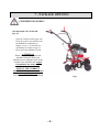
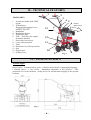
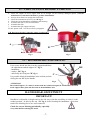
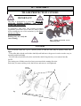
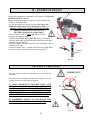
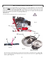
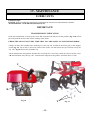
03/07
GB
MOTORHOE RL 3 (1+1)
USER’S MANUAL
TABLE OF CONTENTS
READ THIS MANUAL CAREFULLY
All rights reserved.
This manual cannot be either reproduced or released without the
manufacturer’s prior written consent.
PRINTED IN ITALY
1 – FOREWORD
This symbol is used to highlight an important safety information. If
this information is ignored, people are in danger either of possible
injures – even serious ones – or death.
IMPORTANT
This term highlight special precautions to be taken in order not to
damage the machine.
1.
FOREWORD
Pag. 0
2.
IDENTIFICATION AND MARKING
Pag. 0
3.
CONDITIONS AND USE LIMITS
Pag. 1
4.
WARRANTY
Pag. 1
5.
MACHINE START
Pag. 1
6.
SAFETY RULES
7.
PACKAGE OPENING
Pag,4
8.
WARNING SIGNS
Pag. 5
9.
CONTROL SIGNS
Pag. 5
Pag.2-3
10. TECHNICAL FEATURES
Pag.6
11. TECHNICAL DATA
Pag.6
12. PRECAUTIONS BEFORE STARTING
Pag.7
13. HANDLEBARS ASSEMBLING
Pag.7
14. ASSEMBLY
Pag.8
15. ENGINE START-UP
Pag.9
16. SAFETY DEVICES
Pag.9
17. CONTROLS WORKING
Pag.10
18. ADJUSTMENTS
Pag.11
19. MAINTENANCE
Pag.13
ENGINE: Use and maintenance instructions of this engine
are mentioned in the relative manual, copy of which is
always supplied with every machine.
2 – IDENTIFICATION AND MARKING
Machine serial number is printed on the drive box.
IMPORTANT NOTE
Always mention the machine serial number when calling our technical service or when ordering spare parts.
MARKING
Marking Sample
CE mark is on the handle support.
-0-
3-WARRANTY
3-CONDITIONS AND USE
LIMITS
.
This manual gives you general information on how this
machine should be used and maintained. For any
technical problem, please, call Your confidential dealer.
•
This machine has been designed to be used in
compliance with what specified in the machine
descriptions and safety warnings of this instructions
manual.
•
Any other use is not allowed. The manufacturer is
not responsible for damages caused by any use then
the intended use. The user is fully responsible for
any possible risk.
•
Use, maintenance and repair clauses prescribed by
the manufacturer are also integral part of the
machine intended use.
•
Only people familiar with this machine and well
aware of its hidden risks can use, repair and
maintain it.
•
The manufacturer is not responsible for damages
caused by non-authorized changes made on this
machine.
•
Besides warnings mentioned in this manual, please,
also comply with general regulations on safety and
accident prevention of EEC and the country in
which this machine will be operating.
If in doubt on causes and possible solutions for a certain
trouble, please, call our authorized dealer.
This should be absolutely done during the warranty
period, since any repair made by non-authorized
workshops makes this warranty null and void.
Bear always in mind that the authorized dealer has all
special tools, technical specifications and spare parts
necessary for properly fixing the machine.
Therefore, he should be called in case of any doubt on
maintenance specifications and/or procedures. Some
pages of this manual might not be perfectly right due to
misprints or production changes. For this reason, call
Your dealer before being perfectly familiar with this
machine and personally maintaining this machine. For
further information on use and maintenance of this
machine, ask your authorized dealer for the proper
technical manuals.
Our materials have 12 months warranty (coverings and
electrical parts are not included). The manufacturer
agrees on replacing those parts considered as faulty free
of charge. Purchaser will be charged with labour costs –
necessary for repairing the machine – and possible
transport costs. Both the warranty claim and the returned
piece should always be addressed to our Spare Parts
Department and accompanied by regular freight bill
mentioning all the machine details.
As far as materials available on the market – especially
engines – are concerned, regulations of our supplier will
apply and applications for possible technical service
should be addressed to the local specialized technical
service centres.
.
5 – MACHINE START
READ CAREFULLY THE WHOLE MANUAL BEFORE STARTING THIS
MOTORHOE
NOTE:
The manufacturer aims at ever improving both design and quality of his products. As a consequence, even though
this manual includes latest and most up-dated information available when printed, there might be small differences
between Your power hoe and the information reported in this manual. For any doubt or uncertainties on this
manual, please call our authorized dealer. This manual is integral part of this power hoe and should always
accompany this machine when sold.
-1-
6 - USE
INFORMATION ON A SAFE USE OF THIS MACHINE
1) This machine has been designed and manufactured for being used by one operator only, and is driven by means of
the appropriate handlebars. Any other use is not permitted.!
2) Before operating the machine, read the Use and Maintenance manual thoroughly, so that you are fully aware of all
the operating controls and safety aspects of the machine.
3) Do not under any circumstances transport people or objects on the machine.
4) Always ensure that the machine’s safety devices are correctly mounted and in perfect working condition..
5) Before use, check that all the controls, in particular the clutch, and the Motorstop are in good
working order.
6) Any modifications or spurious parts being fitted without the Manufacturer consent will nullify the guarantee, and
any possible resulting damage will not answered for.
7) This machine must not be used by children or inexperienced persons.
8) Before operating the machine, check that the area is clear and free of debris and that there are no people within the
working area (danger zone). The operator, will be held responsible for the safety of third parties, if these are found
within the working area of the machine. Do not use the machine under these conditions.
9) keep clear of cutting blades at all times while the machine is in operation. Pay particular attention when reversing;
keep hands and feet clear.
10) Use the machine only with the handles in the correct working position. This allows a safe working distance
between the operator and operating area.
11) Use only original accessories and spare parts to guarantee safety and correct operation of the machine.
12) Stop engine before refuelling and remove ignition key (if fitted).
13) Handle the fuel with care to avoid spilling on the machine; clean any spillage immediately.
14) Never refuel in confined places, in vicinity of open flames or near the source of sparks. No smoking!
15) Before starting the engine, check that all the controls are in the idle position.
16) Do not smoke when starting the engine!
17) Do not run the machine in a confined area as toxic exhaust gas can kill.
18) Plan your work before commencing.
19) Do not use the machine when you are tired.
20) Engage the clutch gradually; sudden engagement could cause the machine to rear up.
21) The area next to the engine exhaust will most likely reach temperatures above 80°. Attention! Danger of scalding.
22) Always wear close fitting clothes and anti-slip shoes or boots. For safety reasons avoid using loose clothing. .
23) Make regular checks that all bolts and nuts are well tightened.
-2-
24) Keep the area of work clear and clean.
25) Only use the machine in clear visibility.
26) Avoid working with blunt cutting blades. .
27) Pay maximum attention and use good sense when operating the machine.
28) If you hit any objects during work, stop the machine and check for any damage immediately.
29) During movement to and from the area of work, disengage the Power Take Off. (P.T.O).
30) Do not under any circumstance attempt to by-pass the motor-stop device or remove the disengagement device. The
machine would result having no safety precautions and would be extremely dangerous.
31) The machine’s speed must always suit the conditions and the environment.
32) Do not perform cleaning or maintenance operations of the machine when the engine is running.
33) Avoid sharps turns when travelling up hill, down hill or across steep slopes.
34) In steep descents, do not disengage the drive and do not change gear.
35) When possible, avoid working up or down hill .Always travel across the slope.
36) Do not work on very steep slopes (max.30%).
37)Avoid overfilling the fuel tank.
38) If there is fuel in the tank, avoid tilting the machine during maintenance or adjustment.
39) During use, keep the hot sections of the engine (i.e. cylinder head, exhaust, etc.) clean to avoid a build up of debris
that will overheat the engine.
40) Whenever possible, stop the machine on level ground.
41) If leaving the machine for a long time, ensure it is inaccessible to children and inexperienced people. Close the fuel
tap (if fitted).
42) Do not leave the machine with the engine running.
43) The maintenance instructions of the machine must always be carefully followed and worn parts replaced when
necessary.
44) If the machine is to remain unused for some time, clean it accurately and insert the appropriate protections.
45) Apart from the previous items, it is necessary to take heed of the specific safety norms in force in the Country
where the machine is operating.
-3-
7 – PACKAGE OPENING
CRUSHING DANGER !!
NB: MACHINE NET WEIGTH
Kgs. 40.
-
Open the carton from the upper side
Keep away all the free elements (for
the handlebars assembling see
chapter 13 pag. 7, for the tiller set
assembling see chapter 14 pag. 8)
-
Keep away the machine’s body
ATTENTION
When You are keeping away the
machine from the carton, pay
attention to use adequate strips to the
weight of the machine and respect
scrupulously the safety rules.
EFFECT THE CORRECT
ASSEMBLING of the free elements
on the machine’s body
(see chapters 13 et 14 for assembling
Fig. 1
-4-
8 – WARNING SIGNS
“WARNING” Comply with what
specified in control warning and
warning signs.
“DANGER”
Risk of fire.
Read use instruction !!
“DANGER”
Blades and rotating parts in
operation. Keep hands and feet
away...
“DANGER”
Risk of burns.
“DANGER”
Keep children away from the
machine.
9 – CONTROL SIGNS
Engage tiller movement
FORWARD (F) AND
REVERSE SPEED (R)
SELECTOR
(NEUTRAL in central
position)
ACCELERATOR HANDLE
WITH ENGINE STOP AND
STARTER.
ATTENTION
THIS SELECTOR IS
LOCATED DIRECTLY ON
THE GEARBOX LEVER
-5-
10 – TECHNICAL FEATURES
1
2
MAIN PARTS
1.
2.
3.
4.
5.
6.
7.
8.
9.
10.
11.
12.
13.
3
Accelerator handle with STOP
engine.
Transmission
Engaging/Disengaging Lever –
SAFETY DEVICE
Handlebars
Handlebars adjuster
Engine pull start
Tank – Fuel filler (See engine
instruction booklet)
Front wheel (accessory)
Cover tiller protection
Tiller
Extension Cover tiller protection
Spur
Support spur
Gearbox lever
4
5
6
SPEED
DIRECTION
13
12
7
11
10
9
Fig. 2
8
11 – TECHNICAL DATA
4 stroke engine
Recoil starter – Transmission by gears – Clutch by belt with lever engaging/disengaging –
1 forward speed + 1 one reverse – Handlebars adjustable in any position – Tiller
protection cover with extension – Safety device for advancement stopping if the operator
is absent
Fig. 3
-6-
12 – PRECAUTIONS BEFORE STARTING
1. Check the engine oil level; engine with no oil enough can be seriously damaged (please, read the
manufacturer’s instruction-booklet to get more information).
2. Always check if there is enough fuel in the tank.
3. Check the transmission oil level, cap “B” fig. 5.
4. Check the correct handlebars adjustment and blocking.
5. Assemble the tiller covers and extensions..
6. Assemble the tiller.
7. Assemble the spur support and spur.
For the points 4 and 7 see the successive paragraphs.
N.B. Do always the above when the engine is switch off!!
A
B
Fig. 4
Fig. 5
13 – HANDLEBARS ASSEMBLING
Is necessary thread into the pivot the support handlebars:
- the adjustment toothed support “C” fig. 6,
- handlebars
- washer “RS” fig. 6,
- and finally the fixing nut ”D” fig. 6.
D
C
It is possible block the handlebars in the wished position
closing the nut “D” by the handle.
Fig. 6
ATTENTION!
The toothed support “C” must be turned with the round teeth upward. Furthermore the teeth
on the support must joint with the teeth on the handlebars base.
HANDLEBAR ADJUSTMENT
IMPORTANT!
Handlebar is adjustable in height and on the side ways with the possibility to block it in the
wished position : do this by the nut “D” fig. 6,.After blocking the handlebars, check that
teeth of the blocking device are well connected.
Check the correct blocking periodically, especially
every time before starting the work.
-7-
RS
14 – ASSEMBLY
TILLER PROTECTION COVERS
IMPORTANT!
The tiller is protected by a cover that MUST BE
ALWAYS FITTED DURING THE WORK
WITH THE MACHINE.
In compliance with safety and accident prevention
regulations, protection covers must be always fitted
before starting the use of the motorhoe by the fixing
screws, see fig. 7.
During every use verify the
correct fixing.
Fig. 7 Tiller protection covers
and fixing nuts.
TILLER
The tool-holder shaft has a got a cylinder profile so that the tiller may be quickly fitted. (see
fig.8).
- Clean tiller-hubs (1),the tool-holder shaft (2) and lubricate with grease in order to make easy its
assembly and disassembly.
- Fit tiller hubs (1) and disc (3) on the tool-holder shaft fixing them by screw (4) and nut (5).
NOTE
The cutting part of blades must be always put towards the running direction.
Each time you start working verify that screws and nuts are well tightened.
SPEED
COURSE
4
1
1
3
2
Fig. 8
5
- 8-
15 – ENGINE START-UP
E
Follow the instructions contained in the engine’s USE AND
MAINTENANCE booklet..
Before starting the engine up, always check the following :
- There is fuel in the tank;
- oil is at the right level in the gear-box (fig. 5 part. B);
- Hold the clutch control lever lifted(fig. 11 part.2 ),
NEVER FASTEN UP OR BLOCK THIS LEVER!!
- Make sure that the gear shift lever is in
- NEUTRAL position (see control signs).
- Put accelerator lever in starter (fig. 10, lever with
correspondant sign) position ;
- Hold the start handle (fig. 9 part. E) of the recoil starter
with one hand only and pull smoothly until the ratchet gear
engages and pull sharply;
- Once the engine starts, the rope has to be left gently as far as
completely wound;
- Once the engine starts – put the accelerator lever (fig. 10) to
the lowest gear position and let the engine warm up.
Fig. 9
starter
Lowest
gear
Fig. 10
16. SAFETY DEVICES
IMPORTANT!
The main function of the lever “2” fig. 11 is to put the tiller in
movement.
2
This safety device disengage the tiller if the operator , for any
possible reason, leave the hand “F” fig. 11.
IS VERY IMPORTANT, BEFORE USING THE
MOTORHOE, VERIFY CAREFULLY THE RIGHT
FUNCTIONALITY OF THE SAFETY DEVICE (. IF
YOU HAVE ANY DOUBT ABOUT THE CORRECT
FUNCTIONALITY,
CONTACT
OUR
AUTHORIZED AFTER SALE SERVICE POINT.
F
IS FORBIDDEN FASTEN UP OR BLOCK THE
CLUTCH LEVER WITH THE HANDLE ”F”
Fig. 11
- 9-
17 – CONTROLS WORKING
ACCELERATOR LEVER
MAX
For engine Honda GCV 135:
STARTER
- Lever completely behind MIN
- Lever completely forward MAX
- Lever in MAX position and also in
STARTER position
- Lever completely down stops the engine.
MAX
MIN
Fig. 12
STOP
CLUTCH LEVER
- Lever (part.2 fig.13) down: transmission engaged, motorhoe
goes forward or back, depending from the speeds engaged;
- Lever (part.2 fig.13) up: transmission disengaged, the motorhoe
stops;
- For adjust the belt’s tension, act on the adjuster
(part. 1 fig. 13).
2
1
IS VERY IMPORTANT BEFORE USING THE
MOTORHOE, CHECK THE CORRECT FUNCTIONALITY
OF THE SAFETY DEVICE.
DON’T FASTEN UP OR BLOCK THIS LEVER
Fig. 13
SPEEDS ENGAGEMENT
1. Keep the clutch lever (part. 2 fig.13) up.
2. Put the control speeds lever (part. 3 fig.14) in the wished
position. See the speeds sticker on the gearbox rod (fig.14
and control signs);
3. Speed up the engine by the red hand (fig.12) and put
down gradually the clutch lever (part. 2 fig.13) for
putting in movement the motorhoe..
4. Keep the clutch lever up for disengage the speeds and put
the lever (part. 3 fig.14) in neutral position.
WARNING
Is always necessary put the engine at the lowest gear for
changing the speeds, leaving up the clutch lever.
3
Fig. 14
- 10-
18 - ADJUSTMENTS
SPUR AND SPUR COUPLING
The spur coupling “G” fig. 15a must be assembled to the rear part of the motorhoe’ body by the spline
“H” fig. 15a, fixed with the key “I” fig. 15a.
The spur “L” fig.15a must be threaded inside the hole of the spur support and fixed by the screw M”.
.
The spur coupling can roll on the key so that the spur is free to swing for a certain angle.
So is possible to adjust. :
- The spur’s deep.
- Turned spur solution, see fig. 15b.
H
G
M
Fig. 15a
L
I
Fig. 15b
- 11 -
BELT TENSION AND CLUTCH LEVER
(fig. 17b)
Remove
protection cover (fig. 16 Part. N) unscrewing the 2 screws (fig. 16 Part. O). Verify that belt (fig.
17b) is well pulled with clutch lever down (fig. 13 e 17a Part. 2) while with the same lever up, belt is free
to move inside pulleys (fig. 17b Part. PM e PD). On the contrary it is necessary put the engine in its right
position unscrewing its screws (fig. 16 Part. Q) by sliding it along slots of its support. Done this adjustment
fix the engine and fit the protection cover again (fig. 16 Part. N).
IMPORTANT!
It is better that this adjustment is done by a specialized person.
Fig. 16
Q
N
O
Belt tighter
EP Engine pulley
Belt
2
1
Fig. 17a
Fig. 17b
PD Driving pulley
The belt tension is granted during the working from the belt tighter, controlled by the lever (part. 2 fig.
17a). So, during the belt tension adjustment can be necessary act also on the lever’s (part. 2 fig. 17a)
adjuster (part. 1 fig. 17a).
- 12 -
19 - MAINTENANCE
LUBRICANTS
Lubricants types
ENGINE: Follow carefully the instructions contained in the relevant use and maintenance booklet.
TRANSMISSION: AGIP DIESEL SIGMA SAE 30.
IMPORTANT!
TRANSMISSION LUBRICATION
Check the transmission oil level by the screw “B” located on the left part on the gearbox (fig. 5-18). Never
put oil beyond the level for the correct working of the clutch.
CHECK THE OIL LEVEL EVERY TIME THAT YOU ARE GOING TO USE THE MOTORHOE.
Change oil after 300 working hours, draining it by the cap “S”, located on the lower part on the support
crown (fig. 19). For do this, is necessary unscrew the screws “T” that closes the cap. Put fresh oil by the
cap “U” fig. 18, that is also a breather cap.
All the transmission and gearbox elements are in oil bath. So is necessary check the oil level by the screw
“B” and add fresh oil by the cap “U”, located on the left part on the gearbox (from the driver’s side).
U
B
S
Fig. 18
T
- 13 -
Fig. 19
IF YOU NEED SPARE PARTS PLEASE PUT YOU IN TOUCH WITH
HOW TO DO IT !!
CLEARLY SPECIFYING IN WRITING
a) NAME OF THE MACHINE
b) FRAME NUMBER
c) POSITION, CODE NUMBER AND DESCRIPTION
d) QUANTITY
FOR ANY SPAREPART YOU NEED CONSULTING
THE RELEVANT SPAREPARTS BOOK.
Le descrizioni, le illustrazioni e le caratteristiche tecniche qui riportate, non sono vincolanti per la Casa Costruttrice che le comunica
a semplice titolo illustrativo, riservandosi la facoltà di modifiche in qualsiasi momento allo scopo di migliorare costantemente i
propri prodotti, senza l’obbligo di aggiornarle in questa pubblicazione.
Proprietà letteraria e artistica della Meccanica Benassi SpA.