1
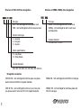
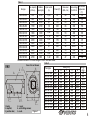
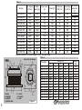
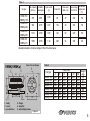
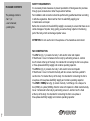
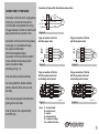
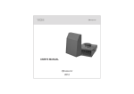
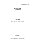
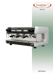
VENTS VKV/VKH/VKMK/VKMKp
ROOF CENTRIFUGAL FANS
USER’S MANUAL
2010
APPLICATION
VENTS VKV/ VKH/ VKMK/ VKMKp the roof centrifugal fan
enclosed in metal body, with input opening diameter 220
to 500 mm (hereinafter named as "the fan") are designed to
use in ventilation systems for industrial premises, swimming
pools, multi-apartment housing, offices, hospitals,
restaurants etc., being heated during winter season. They are
manufactured according to TU U V.2.5-29.2-30637114-012:2006.
The air coming out the fan should not contain dust, other
solid admixtures, sticky substances, and fibrous materials.
The ambient temperature should not exceed the limits indicated
in Table 1, 3, 5.
The fan should be installed vertically on the output air duct shaft
and may be used only for exhaust ventilation.
The fan is designed for long-term operation without
disconnection with the electricity supply.
By the type of protection against electrical shock the fans belong
to Class 1 devices according to GOST 12.2.007.0-75.
The degree of protection against access to the hazardous parts
and water penetration is IPX4.
Type of the climatic modification of the fan is UHL 4.2 according
to GOST 151590-69.
MAIN SPECIFICATIONS
The fans' designations, their parameters, and connection
dimensions are provided in tables 1, 2, 3, 4, 5, 6 and on
figs. 1, 2, 3.
Design of the fans is being constantly perfected, so some models
could slightly differ from the ones, described in this certificate.
2
Structure of VKV, VKH fans designation.
Structure of VKMK, VKMKp fans designation.
xxx xxx
xxx x x xxx
Fan type:
VKV - roof centrifugal fan with square cover
VKH - roof centrifugal fan with low square cover
Electric motor type:
2 - two-pole
4 - four-pole
6 - six-pole
Fan type:
VKMK - roof centrifugal fan with round cover
VKMKp - roof centrifugal fan with round cover
and base plate
Impeller diameter:
150; 200; 250; 315 mm
Mains specifications:
E - one phase
D - three phases
Impeller diameter:
220; 225; 250; 280; 310; 355; 400; 450; 500 mm
Designation examples:
3
VKV 2E 280 - roof centrifugal fan with two-pole one-phase
electric motor and 280 mm impeller diameter.
VKMK 200 - roof centrifugal fan with 200 mm inlet pipe.
VKH 4E 310 - roof centrifugal fan with low cover, four-pole
one-phase electric motor and 310 mm impeller diameter.
VKMKp 150 - roof centrifugal fan with base plate and
150 mm inlet pipe.
Table 1
Fan type
Max .capacity
(m3/hour)
Rotation
speed (rpm)
Input current
(A)
Power (W)
0,38
700
2700
VKV 2Е 220
0,6
900
2650
VKV 2Е 225
0,7
1300
2600
VKV 2Е 250
1,0
1780
2700
VKV 2Е 280
0,54
1820
1370
VKV 4Е 310
0,32
1950
1400
VKV 4D 310
1,12
2800
1420
VKV 4Е 355
0,52
2350
1400
VKV 4D 355
2,4
3400
1400
VKV 4Е 400
0,7
3800
1430
VKV 4D 400
3,1
3850
1350
VKV 4Е 450
0,82
4300
1430
VKV 4D 450
1,82
4700
880
VKV 6Е 500
Allowable deviation of mains voltage: ±10% of the rated value.
Cover 2 is not shown
VKV
2
D
В
3
1 - body;
3 - impeller;
5 - junction box;
4
2 - cover;
4 - self-cutting screws;
6 - nuts.
С
5
Mains voltage
(V) at 50 Hz
Max. ambient
temperature
(°C)
49
49
65
66
45
53
46
53
52
52
53
53
47
230
230
230
230
230
400
230
400
230
400 Y
230
400 Y
230
+55
+55
+50
+50
+85
+65
+50
+70
+80
+60
+50
+50
+50
Table 2
Fan type
6
Н
А
1
85
135
155
225
120
110
245
170
480
385
640
470
385
Noise level
(dBA, 3 m)
VKV 2Е 220
VKV 2Е 225
VKV 2Е 250
VKV 2Е 280
VKV 4Е 310
VKV 4D 310
VKV 4Е 355
VKV 4D 355
VKV 4Е 400
VKV 4D 400
VKV 4Е 450
VKV 4D 450
VKV 6Е 500
А
460
460
520
520
560
560
783
783
783
783
872
872
872
В
335
335
400
400
435
435
595
595
595
595
665
665
665
Size (mm)
С
245
245
330
330
330
330
450
450
450
450
535
535
535
Н
275
275
275
275
330
330
420
420
420
420
454
454
454
D
213
213
286
286
286
286
438
438
438
438
438
438
438
Weight
(kg)
8,9
9,6
12,8
12,7
17,8
17,8
22,0
22,0
27,5
27,5
29,5
29,5
33,8
Figure 1
4
Table 3
Fan type
Max .capacity
(m3/hour)
Rotation
speed (rpm)
Input current
(A)
Power (W)
0,38
700
2700
VKH 2Е 220
0,6
900
2650
VKH 2Е 225
0,7
1300
2600
VKH 2Е 250
1,0
1780
2700
VKH 2Е 280
0,54
1820
1370
VKH 4Е 310
0,32
1950
1400
VKH 4D 310
1,12
2800
1420
VKH 4Е 355
0,52
2350
1400
VKH 4D355
2,4
3400
1400
VKH 4Е 400
0,7
3800
1430
VKH 4D 400
3,1
3850
1350
VKH 4Е 450
0,82
4300
1430
VKH 4D 450
1,82
4700
880
VKH 6Е 500
Allowable deviation of mains voltage: ±10% of the rated value.
2
А
Н
VKH
Cover 2 is not shown
4
1
В
3
1 - body;
3 - impeller;
5 - eyebolt;
7 - junction box.
5
D
С
2 - cover;
4 - screws;
6 - nuts;
7
Figure 2
Mains voltage
(V) at 50 Hz
Max. ambient
temperature
(°C)
49
49
65
66
45
53
46
53
52
52
53
53
47
230
230
230
230
230
400
230
400
230
400 Y
230
400 Y
230
+55
+55
+50
+50
+85
+65
+50
+70
+80
+60
+50
+50
+50
Table 4
Fan type
6
5
85
135
155
225
120
110
245
170
480
385
640
470
385
Noise level
(dBA, 3 m)
VKH 2Е 220
VKH 2Е 225
VKH 2Е 250
VKH 2Е 280
VKH 4Е 310
VKH 4D 310
VKH 4Е 355
VKH 4D 355
VKH 4Е 400
VKH 4D 400
VKH 4Е 450
VKH 4D 450
VKH 6Е 500
А
338
338
365
365
400
400
550
550
550
550
640
640
640
В
335
335
400
400
435
435
595
595
595
595
665
665
665
Size (mm)
С
245
245
330
330
330
330
450
450
450
450
535
535
535
Н
228
228
265
265
250
250
348
348
348
348
400
400
465
D
213
213
286
286
286
286
438
438
438
438
438
438
438
Weight
(kg)
6,3
6,9
10,1
10,2
10,2
10,2
15,6
15,6
21,0
20,9
22,7
22,7
26,6
Table 5
Fan type
Rotation
Max. Capacity
speed (rpm)
(m3/hour)
VKMK 150
VKMKp 150
VKMK 200
VKMKp 200
VKMK 250
VKMKp 250
VKMK 315
VKMKp 315
Input current
(A)
Power (W)
Noise level
(dBA, 3 m)
Mains voltage
(V) at 50 Hz
Max. ambient
temperature
(°C)
555
2705
0,43
98
47
230
+55
950
2375
0,67
154
48
230
+50
1310
2790
0,85
194
52
230
+50
1880
2720
1,34
296
54
230
+45
Allowable deviation of mains voltage: ±10% of the rated value.
Cover 3 is not shown
VKMK(VKMKp)
3
Table 6
5
6
Fan type
D1
Н
L
А
4
1
1 - body;
3 - cover;
5 - junction box;
D2
2
2 - flange;
4 - impeller;
6 - self-cutting screws.
В
VKMK 150
VKMK 200
VKMK 250
VKMK 315
VKMKp 150
VKMKp 200
VKMKp 250
VKMKp 315
А
440
440
590
590
440
440
590
590
В
330
330
450
450
330
330
450
450
Size (mm)
H
L
230
30
238
30
249
30
269
30
230
2
2
238
249
2
269
2
D1
403
403
403
503
403
403
403
503
D2
150
200
250
315
150
200
250
315
Weight
(kg)
7,2
8,1
10,1
10,1
8,2
9,3
12,3
12,2
Figure 3
6
PACKAGE CONTENTS
The package contains:
- fan: 1 pc
- user’s manual;
- packing box.
SAFETY REQUIREMENTS
It is necessary to take measures to prevent penetration of black gases into premises
through open smoke ducts or other fire-prevention facilities.
Fan installation and connection should be performed by qualified electrician according
to effective regulations. Disconnect fan from the electricity supply prior
to maintenance and repair.
Before fan connection to the electricity supply is necessary to ensure that there are no
visible damages of impeller, body, grating, as well as foreign objects in the blowing
part of the body, which can damage impeller vanes.
ATTENTION: Do not use the fan in the explosive or fire-hazardous environment.
FAN CONSTRUCTION
The VKV fan (fig. 1) consists of a body 1 with electric motor and impeller
3 fitted therein. Cover 2 is fastened to the body by self-cutting screws 4. Junction
box 5 is fixed at the top of the body. It is intended for connecting the fan to one-phase
or three-phase electricity supply and contains operating capacitor.
The VKH fan (fig. 2) consists of a body 1 with electric motor and impeller
3 fitted therein. Cover 2 is fixed to the body with two screws 4 and two eyebolts 5.
Junction box 7 is fixed at the top of the body. It is intended for connecting the fan to
one-phase or three-phase electricity supply and contains operating capacitor.
The VKMK / VKMKp fans (fig. 3) consist of a body 1 with flange 2 in a shape of a
box (VKMK) or a plate (VKMKp). Electric motor with impeller 4 is fitted inside the body.
Cover 3 is fastened to the body by self-cutting screws 6. Junction box 5 is fixed
at the top of the body. It is intended for connecting the fan to one-phase or
three-phase electricity supply and contains operating capacitor.
7
CONNECTION TO THE MAINS
Connection scheme of the fan with one-phase motor
х
Connection of the fan to the single-phase
mains (fig. 4) should be through the
circuit-breaker incorporated into wiring.
The gap between contacts of switch at all
poles should not be less than 3 mm.
Connection of the fan to the three-phase
mains (figs. 5, 6) should be through
the 3-pole circuit-breaker
with thermomagnetic tripper.
Connection for the fan with the electric
motor and fitted overheating control
sensor should be made
according to Fig. 7, 8.
A fan should be mounted vertically.
Air moving direction should coincide
with the direction of the arrow on the
fan body.
black
~230V, 50Hz
blue
N
Figure 4
D-type connection of the fan
with three-phase motor
Y-type connection of the fan
with three-pase motor
х
black
L1
U1
L2
V1
blue
L2
L3
W1
brown
green
white
yellow
green / yellow
L3
V1
W1
L1
U1
U2
V2
W2
PE
blue
brown
green
white
yellow
green / yellow
PE
М
Figure 6
К
D-type connection of the fan
with three-phase motor and
overheating control sensor
К
X
U1
V1
W1
U2
V2
W2
TW 1
TW 2
S2
black
W2
Y-type connection of the fan
with three-phase motor and
overheating control sensor
L1
L2
L3
S1
х
U2
V2
М
Figure 5
black
blue
brown
green
white
yellow
М
*
*
green / yellow
L1
L2
L3
S1
S2
N
PE
* - one color
Figure 7
where
A fan is fixed on the output shaft by
four M10 nuts.
М
green / yellow
N
PE
A fan may be equipped with protective
grating at the input side.
brown
S
L
X
U1
V1
W1
U2
V2
W2
TW 1
TW 2
black
blue
brown
green
white
yellow
М
*
*
green / yellow
* - one color
Figure 8
X - terminal block;
M - electric motor;
S - switch;
K- solenoid starter;
S1 - switch-on button;
S2 - swithch-off button.
8
MANUFACTURER'S WARRANTY
MAINTENANCE
Maintenance of the fan should be carried out only
after disconnecting it with the mains. Maintenance
comprises periodical cleaning of the surfaces from
dust and dirt, when the fan is disconnected with the
mains. To remove the dust, use a soft dry brush or
compressed air.
Blades of the impeller require careful cleaning every
6 months.
The manufacturer, Joint-Stock Company “Ventilation systems ",
guarantees the normal operation of the fan during 24 months
from the date of sale through the retail outlet under condition
that the rules of transportation, storage, installation
and operation were followed.
For this purpose:
- loosen the self-cutting screws 4 (fig. 1), 6 (fig. 2)
screws 4 and eyebolts 5 (fig. 2)
- detach cover 2 (fig. 1, 2), cover 3 (fig. 3) from the body.
Using the water solution of detergent, clean the blades
of the impeller, avoiding fluid penetration onto the
electric motor.
In case of any failures in operation of the fan through the
manufacturer's fault during the warranty term, the consumer has
the right to have the fan replaced in accordance with the Article
14 item 9 of The Law of Ukraine "On consumer rights protection".
When the mark about the sale date is absent, the warranty period
is calculated from the date of manufacture.
Replacement will be made in the office located at:
1 Mikhaila Kotzubinskogo St., Kiev 01030 Ukraine.
KEEPING CONDITIONS
Keep the fan in the manufacturer's packaging in a well
vented premise at the temperature from +5°C to
+ 40°C and relative humidity not exceeding 80 %
(at T = 20°C).
9
The presence of acids, alkalis and other aggressive
substances in the air is not allowed.
ACCEPTANCE CERTIFICATE
Fan " VENTS VKV__________________"
"VENTS VKH __________________"
"VENTS VKMK _________________"
"VENTS VKMKp _________________"
(fill as appropriate, delete the rest)
complies with the TU U V.2.5-29.2-30637114-012:2006
and is accepted as ready for operation
Stamp of the inspector
Manufacture date
Sold
name of the trading company, stamp of the shop
Date of sale
V14EN-02