1
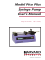
Model Pico Plus
Syringe Pump
User’s Manual
Pump 11 Pico Plus
MA1 70-2213
Publication 5412-001-REV-E
WEEE/RoHS Compliance Statement
EU Directives WEEE and RoHS
To Our Valued Customers:
We are committed to being a good corporate citizen. As part of that commitment,
we strive to maintain an environmentally conscious manufacturing operation. The
European Union (EU) has enacted two Directives, the first on product recycling
(Waste Electrical and Electronic Equipment, WEEE) and the second limiting the use
of certain substances (Restriction on the use of Hazardous Substances, RoHS).
Over time, these Directives will be implemented in the national laws of each EU
Member State.
Once the final national regulations have been put into place, recycling will be offered
for our products which are within the scope of the WEEE Directive. Products falling
under the scope of the WEEE Directive available for sale after August 13, 2005 will
be identified with a “wheelie bin” symbol.
Two Categories of products covered by the WEEE Directive are currently exempt
from the RoHS Directive – Category 8, medical devices (with the exception of
implanted or infected products) and Category 9, monitoring and control instruments.
Most of our products fall into either Category 8 or 9 and are currently exempt from
the RoHS Directive. We will continue to monitor the application of the RoHS
Directive to its products and will comply with any changes as they apply.
• Do Not Dispose Product with Municipal Waste
• Special Collection/Disposal Required
Table of Contents
H a r v a r d A p p a r a t u s Pico Plus S y r i n g e P u m p
1
SUBJECT
PAGE NO.
General Information - Warranty and Repairs ......................2
General Safety Summary ....................................................3-4
Introduction:
Theory of Operation ............................................................5
Features ..............................................................................5
Front and Rear Views ............................................................6
Installation:
Initial Setup & Location Requirements ................................7
Loading the Syringe ............................................................7
Operation:
Getting Started:
Turn Pump ON................................................................8
Function Keys and Run Indicator ....................................8
Entering Syringe Size ......................................................9
Entering Flow Rate Range ..............................................9
Entering Flow Rate..........................................................9
Press Run/Footswitch ....................................................9
Check Syringe ................................................................9
Advanced Features:
Volume Mode ..............................................................10
Power Failure ................................................................10
Changing Rates ............................................................11
Maintenance ................................................................11
Protecting Small, Fragile Syringes ................................11
Appendices:
A. Specifications ................................................................12
B. Table of Popular Syringe Diameters ..............................13
C. Table of Minimum and Maximum Flow Rates ..............14
D. Serial Communication ..............................................16-19
E. RS232 Connections ......................................................20
F. PC Connection ..............................................................20
Publication 5412-001-REV-E
General Information
H a r v a r d A p p a r a t u s Pico Plus S y r i n g e P u m p
2
Serial Number
All inquires concerning our product should refer to the serial number of the unit.
Serial numbers are located on the rear of the chassis.
Calibration
All syringe pumps are designed and manufactured to meet their performance specifications at all rated voltages and frequencies. A calibration certificate is available
upon request. Contact customer service for details and pricing.
Warranty
Harvard Apparatus warranties this instrument for a period of two year from date of
purchase. At its option, Harvard Apparatus will repair or replace the unit if it is
found to be defective as to workmanship or material.
This warranty does not extend to damage resulting from misuse, neglect or abuse,
normal wear and tear, or accident.
This warranty extends only to the original customer purchaser.
IN NO EVENT SHALL HARVARD APPARATUS BE LIABLE FOR INCIDENTAL OR CONSEQUENTIAL DAMAGES. Some states do not allow exclusion or limitation of incidental or consequential damages so the above limitation or
exclusion may not apply to you. THERE ARE NO IMPLIED WARRANTIES OF
MERCHANTABILITY, OR FITNESS FOR A PARTICULAR USE, OR OF
ANY OTHER NATURE. Some states do not allow this limitation on an implied
warranty, so the above limitation may not apply to you.
If a defect arises within the two-year warranty period, promptly contact your local
distributor or Harvard Apparatus, 84 October Hill Road Holliston,
Massachusetts 01746-1388 using our toll free number 1-800-272-2775 (valid
only in the U.S., outside U.S. call 508-893-8999). Goods will not be accepted for
return unless an RMA (returned materials authorization) number has been issued
by our customer service department. The customer is responsible for shipping
charges. Please allow a reasonable period of time for completion of repairs, replacement and return. If the unit is replaced, the replacement unit is covered only for the
remainder of the original warranty period dating from the purchase of the original
device.
This warranty gives you specific rights, and you may also have other rights which
vary from state to state.
Repair Facilities and Parts
Harvard Apparatus stocks replacement and repair
parts. When ordering, please describe parts as
completely as possible, preferably using our part
numbers. If practical, enclose a sample or drawing.
We offer a complete reconditioning service.
CAUTION
This pump is not registered with the FDA and is not for clinical use on human or
veterinary patients. It is intended for research use only.
Publication 5412-001-REV-E
General Safety Summary
H a r v a r d A p p a r a t u s Pico Plus S y r i n g e P u m p
3
Please read the following safety precautions to ensure proper use of your syringe
pump. To avoid potential hazards and product damage, use this product only as
instructed in this manual. If the equipment is used in a manner not specified by the
manufacturer, the protection provided by the equipment may be impaired.
To Prevent Hazard or Injury:
U s e P r o pe r P o w e r S u pp l y
The pump is supplied with an approved power supply and line cord. To maintain
the safety integrity of the device, use only one of the following power supplies:
Ault Inc.
Model No.:
Output:
Input:
PW118
12 Vdc, 1.5 A
100-250 Vac, 50-60 Hz, .5A
Cui Stack
Model No.:
Output:
Input:
SA06N12-V
12 Vdc, 2.0 A
100-240 Vac, 50-60 Hz, .8A
Globtek Inc
Model No.:
Output:
Input:
GT-4201D-12
12 Vdc, 1.66 A
100-240 Vac, 50-60 Hz, 0.6A
U s e P r o pe r L i n e Co r d
Use only the line cord shipped with the product and make sure line cord is certified
for country of use.
Gr o u n d t h e P r o du c t
This product is grounded through the return path of the DC power supply. To avoid
electric shock, use only approved power supply and line cord with the product.
M a k e P r o pe r Co n n e c t i o n s
Make sure all connections are made properly and securely.
O bs e r v e a l l Te r m i n a l R a t i n gs
Review the operating manual to learn the ratings on all connections.
Publication 5412-001-REV-E
General Safety Summary
H a r v a r d A p p a r a t u s Pico Plus S y r i n g e P u m p
4
A v o i d E x po s e d Ci r c u i t r y
Do not touch any electronic circuitry inside of the product.
Do N o t Ope r a t e w i t h S u s pe c t e d F a i l u r e s
If damage is suspected on or to the product do not operate the product. Contact qualified service personnel to perform inspection.
O bs e r v e a l l W a r n i n g L a be l s o n P r o d u c t
Read all labels on product to ensure proper usage.
CAUTION
Refer to Manual
Functional Ground
Terminal
E n v i r o n m e n t a l Co n d i t i o n s
Indoor use only
Temperature 4˚C to 40˚C (40˚F to 104˚F)
Humidity 20% to 80% RH (non-condensing)
Well Ventilated Room
Altitude up to 2000 m
Mains Voltage Fluctuation not to Exceed +/- 10% of Nominal
Transient Over Voltage, Category II
Pump is Rated Pollution Degree 2 in Accordance with IEC 664
Publication 5412-001-REV-E
Introduction
H a r v a r d A p p a r a t u s Pico Plus S y r i n g e P u m p
5
Theory of Operation:
The pico plus is designed as a low cost infusion pump capable of delivering very low
flow rates at low to moderate back pressures.
The pump can hold two syringes of any make from 0.5 µl to 10ml. The diameter
of the syringes is entered via the keypad and the internal microprocessor drives a
precision stepper motor to produce accurate fluid flow.
Non-volatile memory stores the last syringe diameter and flow rate along with other
configuration data.
The “Power Failure Mode” can be set to either turn the pump off in the event of
power failure or to resume pumping when power resumes.
Features:
Bright Display and Easy-To-Use Interface
A new, two-line 16 character display along with six membrane keys make this a
most attractive but powerful, easy-to-use syringe pump. Only two entries are
required to start pumping; syringe Inside Diameter (mm) and pumping flow rates.
The Flow rate can be changed while the Pump is running. Direct enter flowrates in
ml, µl, nl, and pl.
Two Modes of Operation, Constant Flow Rate and Volume
Dispense
The pico plus will operate continuously in RATE mode or accurately dispense a
specific amount of fluid in VOLUME mode. All modes can be operated from keypad, footswitch (included) or external controller via serial connection (included).
Withdraw mode makes it easy to “load” capillaries, pipettes and syringes.
Adjustable end of travel limit stop to protect small syringes.
Smooth Flow
Enhanced micro-stepping pump profiles deliver very smooth and consistent flow,
that is virtually pulse free.
Nonvolatile Memory
The pump remembers its last syringe size, flow rate used and configuration settings.
Power Fail Mode
In a power failure the Pump can either RESUME or STOP pumping when power
is returned.
CE Mark Approved–UL+CSA (ETL)
The pico plus meets all relevant European EMC and Safety requirements for laboratory equipment.
Publication 5412-001-REV-E
Pico Front and Rear Views
H a r v a r d A p p a r a t u s Pico Plus S y r i n g e P u m p
6
Syringe Clamp (5)
Allen Wrench
Syringe Holder (6)
Plunger Retaining Bracket (3)
Pusher Block (2)
Adjustable Stop
Collar (8)
Run LED
Halfnut (1)
Keypad
Serial Connections
Display
Syringe Retaining
Bracket (4)
Infuse
Limit Switch
Adjustable
Stop Pin (7)
Cover
Leadscrew
ETL
Label
Power
Switch
Power Cord
Receptacle
Publication 5412-001-REV-E
Foot Pedal
Receptacle
Reversing
Toggle Switch
Serial Label
Installation
H a r v a r d A p p a r a t u s Pico Plus S y r i n g e P u m p
7
Initial Set-up
1.
Read the manual to become familiar with all features and functions of the pico
plus.
2.
Connect the external DC power supply and line cord to the pump and main
supply.
3.
Turn on main power switch located on the rear panel. The display will now
illuminate indicating that the power connections are correct. The display will
indicate POWER FAIL. (this is normal as the pump indicates on the display
if power was disrupted since last use.)
Location Requirements for the Syringe Pump
• A sturdy, level, clean and dry surface
• Minimum of one inch (2cm) clearance around the pump
• Appropriate environmental conditions
• A well ventilated room
Loading the Syringe
1.
Press the bronze halfnut button (1) on the side of the pusher block to release
it from the leadscrew.
2.
While holding the button ‘in’, slide the pusher block (2) to the left.
3.
Loosen plunger retaining bracket (3) and syringe retaining bracket (4) by
slightly unscrewing the cap screws.
4.
Loosen the thumbscrew on the syringe clamps (5) and rotate the clamp out of
the way.
5.
Lay the syringe into the V-shaped slots on the syringe holder block (6).
6.
Swing the syringe clamps (5) over the syringes and tighten the thumbscrews
to secure the syringe in place.
7.
Slide the syringe retaining bracket (4) up to secure the flange on the syringe
barrel against the syringe holder block.
8.
Press the halfnut button (1) and hold it in while sliding the pusher block up
to the syringe plunger.
9.
Tighten the thumbscrews on the plunger retaining bracket (3).
10. The infuse limit switch is adjusted by loosening the thumbscrew on the back
of the pusher block and sliding the stop pin (7) in or out to the desired location [to protect the syringe from bottoming out].
11. The withdraw limit switch [enclosed in the cover] is adjusted by securing the
stop collar (8) into the desired position.
Publication 5412-001-REV-E
Operation: Getting Started
H a r v a r d A p p a r a t u s Pico Plus S y r i n g e P u m p
8
Getting started
1. Turn Pump ‘ON’
Turn on power using the switch on rear of the pump, the display will light,
and indicate POWER FAIL. (this is normal as the pump indicates on the display if power was disrupted since last use.)
2. Function Keys and Run Indicator
Refer to the colored keypad at the front of the pump to identify the following
functions starting from the right.
RUN/STOP – This turns the pump motor on and off (also accomplished by
pressing the foot switch).
ENTER – This key enters the data that is on the display into the memory of
the pump. Also used to query the flow rate.
DIAM – Used to enter or query the syringe diameter.
SET – This key is used to select which digit of the display is to be changed, to
move the decimal point and to move between modes. Each time the set key is
pressed the underline cursor below the digit or character on the display moves
one step to the right. It is used in conjunction with the ascending and descending keys. When it the display shows the desired the correct value the set key
will advance right to the next digit.
– The ascending and descending keys are used to change the numbers
on the display. Up key makes numbers increase, Down Key makes
numbers decrease. When the underline cursor is placed below the decimal
point, the keys shift the decimal one place up or down.
Run Indicator – When the pump is running, the highly visible, green LED
above the RUN/STOP key will illuminate.
3. Enter Syringe Size
Enter the inside diameter (ID) of the syringe you wish to use. Units are in millimeters (mm).
If you do not know your syringe diameter, refer to appendix B for nominal
inside diameters of most popular syringes. For the greatest accuracy or if your
syringe is not listed in appendix B, measure the inside diameter with a vernier
caliper or other precision measuring tool. Record this value for future use.
Publication 5412-001-REV-E
Operation: Getting Started
H a r v a r d A p p a r a t u s Pico Plus S y r i n g e P u m p
9
Press SET followed by the DIAM key. The previously used diameter will
appear on the display. The underline cursor will appear under the left-most
digit or decimal point. The and keys are used to scroll to the desired
number and the SET key moves the underline cursor one place to the right.
Once the desired diameter is displayed, press the ENTER key to place this
value into memory.
4. Enter Flow Rate Range
Choose your flow rate units; picoliters, nanoliters, microliters or milliliters; per
minute or per hour.
From the initial RATE VOL CONFIG menu, using the or key, move
the underline cursor under the CONFIG mode menu prompt. Press the SET
key to enter the CONFIG mode. Press the SET key again to move the underline cursor to the flow rate choices. Choose your flow rate units while in the
SET:UNITS mode by pressing the or keys to scroll the four flow rate
choices; ml/min, µl/min, ml/hr, µl/hr. Once the desired flow rate units are displayed, press the ENTER key to return to the main SET:CONFIG mode.
Press SET or ENTER again to put your desired flow rate units into memory
and return to the RATE VOL CONFIG menu.
5. Enter Flow Rate
From the initial RATE VOL CONFIG menu, press the SET key to enter the
SET:RATE mode. Each time you change the syringe diameter, the previously
used flow rate is erased. If the syringe diameter is unchanged, the previously
used flow rate will appear on the display. The underline cursor will appear
under the left-most digit or decimal point. The and keys are used to
scroll to the desired number and the SET key moves the underline cursor one
place to the right. Once the desired rate is displayed, press the ENTER key to
place this value into memory.
6. Press RUN Or Foot Switch
Press the RUN/STOP key or press the foot switch to start pump and begin
pumping. The Run Indicator (Green LED above the RUN/STOP key) will
light when the pump is on and pumping.
7. Check Syringe Often
The pico plus pump will shut itself off when the syringe is empty via the infuse
limit switch. If the switch is improperly set or the syringe is overloaded, the
pump will not shut itself off. Although this presents no hazard to the user or
the pump, it is prudent to check the syringe from time to time.
Publication 5412-001-REV-E
Operation: Advanced Features
H a r v a r d A p p a r a t u s Pico Plus S y r i n g e P u m p
10
1. Volume Mode
The pico plus can be set to dispense a precise volume and then stop. To activate the volume dispense mode a target volume must be set.
To set a target volume, at the RATE VOL CONFIG display, move the underline cursor, using the or key, to VOL. Press the SET key to enter the VOL
set mode. Use the or key and the SET key to display a target volume
from 00.01 to 99.99. Volume units are pl (picoliters), nl (nanoliters), ml (milliliters) or µl (microliters). Target volume units are established in the CONFIG
SET:UNITS mode; example: if your pumping units are ml/ min or ml/ hr, then
the volume dispense units will be ml’s. Press the ENTER key to select the
desired target volume. Exit the VOL mode by pressing the ENTER key.
Once you press the RUN key, the pump will run until the target volume is
delivered. The display will show the actual volume dispensed along with the
target volume. Press the RUN key each time you want to repeat the volume
dispense. If you press the STOP key during a volume dispense, you can restart
the pump at the place you stopped by pressing the RUN key again.
To exit the volume dispense mode, set the target volume to 00.00 or turn off
and on the pump via the main power switch. NOTE: In the event of a power
failure, the actual dispensed volume and the target volume are not retained in
memory. This means that while in volume dispense mode, if a power failure
occurred, the pump would not resume volume dispense pumping even if the
POWER ON mode was set to run.
2. Power Failure
In the event of a momentary or prolonged power failure, the pico plus can be
set to either;
a) Resume pumping when power is returned, with “POWER FAIL” on the
display.
b) Not start pumping when power is returned, with “POWER FAIL” on the
display.
To set the power fail mode, at the RATE VOL CONFIG display, move the
underline cursor, using the or key, to CONFIG. Press the SET key to
enter the CONFIG mode options. Use the or key to scroll the CONFIG options until you reach the SET:POWER ON: display. Press the SET
key again moving the underline cursor to the right. Use the or key to
scroll the POWER:ON choices; ‘stop’ or ‘run’. Press the ENTER key to select
either mode. Exit the CONFIG mode by pressing the ENTER key again and
save the POWER:ON setting in memory.
Publication 5412-001-REV-E
Operation: Advanced Features
H a r v a r d A p p a r a t u s Pico Plus S y r i n g e P u m p
11
3. Display Intensity
For varying light conditions, four levels of intensity can be set on the vacuum
fluorescent display
To set the desired display intensity, at the RATE VOL CONFIG display, move
the underline cursor, using the or key, to CONFIG. Press the SET key
to enter the CONFIG mode options. Use the or key to scroll the CONFIG options until you reach the SET:INTENSITY:. Press the SET key again
moving the underline cursor to the right. Use the or key to scroll the
SET : INTENSITY choices; "1", "2", "3", "4" ( 4 is highest intensity, 1 is the
lowest intensity). Press the ENTER key to select the desired display intensity.
Exit the CONFIG mode by pressing the ENTER key again and save the
INTENSITY setting in memory.
4. Changing Rates
If the pump is running at an existing rate it will continue to do so until a new
rate is entered. Except for volume mode, the flow rate can be changed while
the pump is running. As soon as the ENTER key is pressed the pump will
change to the new flow rate. To change rates from the keypad, while in volume mode, the pump must be stopped first. The pump must be stopped to
change the flow rate range (units) while in either mode.
5. Reversing the Flow Direction
The pump is equipped with a reversing switch to toggle from infuse to withdraw. The flow rate will be the same for both infuse and withdraw modes unless
changed manually (refer to #4).
CAUTION: Remember to check the switch before pressing run to ensure it is
indicating the desired direction.
6. Maintenance
Keep the pump clean and dry. Avoid liquid spills that may find their way into
the electronics.
A small container of grease is provided for periodic lubrication of the lead
screw and guide rods. It is important to keep these guide rods clean and lubricated.
To clean the exterior surfaces, use a lint-free cloth to remove loose dust. Use care
to avoid scratching the display window. For more efficient cleaning, use a soft
cloth dampened with water or an aqueous solution of 75% isopropyl alcohol.
If the pump does not work properly, contact Harvard Apparatus for appropriate instructions.
7. Protecting Small, Fragile Syringes
The pico plus will hold microliter size syringes down to 0.5 µl size. These
small syringes have fine wire plungers that may be damaged if allowed to bottom out. Be sure to set the limit switches properly to prevent damage to small
syringes.
Publication 5412-001-REV-E
Appendix A
H a r v a r d A p p a r a t u s Pico Plus S y r i n g e P u m p
12
Pico Plus VPF Specifications
Type
Microprocessor dual syringe, infuse/withdraw
Syringe/Size for Pico Plus
with Holder For:
Plastic or glass
2 Syringes
From 0.5 µ l to 10 ml
Flow Rate Range:
Minimum / Maximum
1.3 pl/min with 0.5 µ l syringe
0.4393 ml/min with 10 ml syringe
0.8788 ml/min using 2 x 10 ml syringes (combined output)*
Calibration
Automatic, enter syringe size up to 16 mm Inside Diameter
Display
2 line, 16 character vacuum fluorescent display and green
run led
Nonvolatile Memory
Stores diameter, rate and configuration settings
Maximum Force
(25 lb.) **
Maximum Pressure
100 p.s.i. with 10 cc syringe; 175 p.s.i. with 1 ml syringe
Drive Motor
1.8° step angle geared 36:1 motor
Step Rate:
Minimum / Maximum
Pusher Advance/Step
1 pulse in 27.6 sec / 200 steps/sec
0.0444 µ m pusher advance per motor step
Pusher Travel Rate:
Minimum / Maximum
0.0388 µ m/min / 0.8333 mm/min
Dynamic Range
1 to 16,384
Leakage to Ground
Typically < 150 µ A
Ground Resistance
Typically < 0.05 ohms
Input Power
12 VDC 1.5 Amps
Input Power Connection
2.5mm ID x 5.5 mm OD male plug
Power Supply
100/250 VAC, 50/60 Hz, 18 Watts External Universal
Power Supply, Use Only a Harvard Apparatus Approved
Power Supply and Line Cord
Size, H x W x D
11.4 x 22.9 x 11.4 cm (4-1/2 x 9 x 4-1/2 in)
Weight
2.3 kg (5 lb)
* Additional accessories are required to achieve this flow rate.
** Actual force is higher, but not recommended for applications requiring more
than 25 lbs of force.
Publication 5412-001-REV-E
Appendix B: Syringe Inside Diameter
H a r v a r d A p p a r a t u s Pico Plus S y r i n g e P u m p
13
–––––––––––––––––––
Terumo
Size
Diameter
3 cc
8.95 mm
5
13.00
10
15.80
1 cc
4.78 mm
–––––––––––––––––––
Sherwood–Monoject
Plastic
Size
Diameter
1 cc
4.65 mm
3
8.94
6
12.70
12
15.90
–––––––––––––––––––
Cadence Science, Inc.
Formly Popper & Sons, Inc.
“Perfektum” Glass
Size
Diameter
0.25 cc 3.45 mm
0.5
3.45
1
4.50
2
8.92
3
8.99
5
11.70
10
14.70
Publication 5412-001-REV-E
–––––––––––––––––
Stainless Steel
Size
Diameter
8 cc
9.525 mm
–––––––––––––––––––
Becton Dickinson
Plastic “Plasticpak”
Size
Diameter
1 cc
4.78 mm
3
8.66
5
12.06
10
14.50
–––––––––––––––––––
Air–Tite “All Plastic”
Size
Diameter
2.5 cc 9.60 mm
5.0
12.45
10
15.90
–––––––––––––––––––
Unimetrics
Series 4000 & 5000
Size
Diameter
10 µl
0.460 mm
25
0.729
50
1.031
100
1.460
250
2.300
500
3.260
1000
4.610
–––––––––––––––––––S
GE
Scientific Glass
Engineering
Size
Diameter
25 µl
0.73 mm
50
1.03
100
1.46
250
2.30
500
3.26
1.0 ml 4.61 mm
2.5
7.28
5
10.30
10
14.57
–––––––––––––––––––
Hamilton–Microliter
Series Gastight
Size
Diameter
.5 µl
0.103 mm
1
0.1457
2
0.206
5
0.3257
10
0.460
25
0.729
50
1.031
100
1.46
250
2.3
500
3.26
1.0 ml 4.61 mm
2.5
7.28
5
10.3
10
14.57
Appendix C: Flow Rates
H a r v a r d A p p a r a t u s Pico Plus S y r i n g e P u m p
14
Syringe
pl/hr
ID (mm) min
max
pl/min
min
max
nl/hr
min
nl/min
min
max
Min
0.1
77.78
9999
1.296
1ul
0.15
172.2
2.870
0.0778 1241
0.0013
20.69
0.1722 2794
0.0029
46.57
2ul
0.21
338.9
5ul
0.33
827.8
5.648
0.3389 5477
0.0056
91.28
13.80
0.8278 9999
0.0138
10ul
0.46
1606
225.4
26.76
1.606
0.0268
437.9
9999
max
25ul
0.73
4044
67.41
4.044
0.0674
1103
50ul
1.03
8043
134.1
8.043
0.1341
2196
100ul
1.46
269.4
16.16
0.2694
4412
250ul
2.3
668.4
40.11
0.6684
9999
500ul
3.26
1344
80.61
1.344
1ml/1000µ l
4.61
2686
161.2
2.686
2.5ml
7.28
6696
401.8
6.697
3ml
8.66
9481
568.9
9.482
5ml
10.3
805.6
13.43
10ml
14.57
1610
26.83
A table of minimum and maximum diameter values
pL/hr max diameter:
1.14
pL/mn max diameter:
8.89
mL/mn min diameter:
0.22
Publication 5412-001-REV-E
0.1612
Appendix C: Flow Rates
15
ul/hr
min
max
ul/min
min
0.0001
1.241
0.0011
0.0003
2.794
0.0027
0.0004
5.477
0.0009
13.52
0.2254
0.0135
0.0002
0.0017
26.28
0.4379
0.0262
0.0004
max
ml/hr
min
max
ml/min
min
max
0.0054
0.0041
66.17
0.0001
1.103
0.0661
0.0011
0.0081
131.7
0.0002
2.196
0.1317
0.0021
0.0162
264.7
0.0003
4.412
0.2647
0.0044
0.0402
656.7
0.0007
10.94
0.6567
0.0109
0.0806
1317
0.0014
21.94
1.317
0.0219
2637
0.0027
43.94
0.0002
2.637
0.4018
6580
0.0067
109.7
0.0005
0.0001
0.0439
6.580
0.1097
0.5689
9313
0.0095
155.2
0.0006
9.313
0.8056
9999
0.0135
219.6
0.0009
13.16
0.0001
0.2196
0.0269
439.4
0.0017
26.36
0.0002
0.4393
1.610
Publication 5412-001-REV-E
0.1552
Appendix D: Serial Communication
H a r v a r d A p p a r a t u s Pico Plus S y r i n g e P u m p
16
Serial connector (RJ-11 style) pinning:
Position*
1
2
3
4
Signal
GND
GND
TxD
RxD
• The connector position as viewed looking into the RJ-11 connector reading left to right
Baud rate and address
The baud rate and address are set in the CONFIG mode, options are described as
follows:
a. Pump Address
To set the pump address, at the RATE VOL CONFIG display, move the underline
cursor, using the or key, to CONFIG. Press the SET key to enter the CONFIG mode options. Use the or to scroll the CONFIG options until you reach
the SET:ADDRESS. Press the SET key again moving the underline cursor to the
right. Use the or to scroll the two digit number fields. Use the or key
and the SET key to display a unique pump address from 00 to 99. Press the
ENTER key to select the desired pump address. Exit the CONFIG mode by pressing the ENTER key again and save the ADDRESS setting in memory.
b. Baud Rate
To set the pump address, at the RATE VOL CONFIG display, move the underline
cursor, using the or key, to CONFIG. Press the SET key to enter the CONFIG mode options. Use the or key to scroll the CONFIG options until you
reach the SET:BAUD. Press the SET key again moving the underline cursor to the
right. Use the or key to scroll the SET:BAUD choices; ‘300’, ‘1200’, ‘2400’
or ‘9600’. Press the ENTER key to select the desired baud rate. exit the CONFIG
mode by pressing the ENTER key again and save the BAUD setting in memory.
Publication 5412-001-REV-E
Appendix D: Serial Communication
H a r v a r d A p p a r a t u s Pico Plus S y r i n g e P u m p
17
Operation with Serial control and external
Run/Stop switch (foot switch)
Mode
Local-Keyboard
Function
Run/Stop
Remote-Serial control
Run
Stop
Exit Remote
Publication 5412-001-REV-E
Operation
Momentary switch contact
If pressed when stopped starts pump motor
(Run LED lights when running) If pressed
when running, stops pump motor
REMOTE mode initiates when pump
receives a CR character (ASCII 13)
REMOTE is displayed on pump display
while in remote mode
RUN Commands the pump motor to start
STP Commands the pump motor to stop
KEY Commands the pump to exit
REMOTE mode
Keyboard Run/Stop key while in
REMOTE mode; will stop pump motor if
running
Will not restart pump motor in REMOTE
mode
While in REMOTE mode, External
Run/Stop connection is ignored
Appendix D: Serial Communication
H a r v a r d A p p a r a t u s Pico Plus S y r i n g e P u m p
18
Commands, Queries and Responses
After each transmission to the pump terminating with a CR character (ASCII 13), the
pump enters remote mode and responds with the three character sequence:
CR
LF
prompt
The prompt character indicates the status of the pump as follows:
prompt
meaning
ASCII code
:
>
*
When stopped
When running forward
When stalled
(ASCII 58 decimal)
(ASCII 62 decimal)
(ASCII 42 decimal)
Pump 11 does not include stall
detection
Serial commands and their meanings:
Commands:
KEY
Return to keyboard control. Exit remote mode
RUN
Start infuse (forward direction)
STP
Stop motor
CLV
Clears volume accumulator to zero
CLT
Clears target volume to zero, dispense disabled
REV
Start (Reverse Direction)
Commands with numbers:
MMD number
Set syringe diameter, units are mm. Rate is set to zero after
MMD command.
PLM
number
Set flow rate and range, units are Picoliters per minute
NLM
number
Set flow rate and range, units are Nanoliters per minute
ULM
number
Set flow rate and range, units are microliters per minute
MLM
number
Set flow rate and range, units are milliliters per minute
PLH
number
Set flow rate and range, units are Picoliters per hour
NLH
number
Set flow rate and range, units are Nanoliters per hour
ULH
number
Set flow rate and range, units are microliters per hour
MLH
number
Set flow rate and range, units are milliliters per hour
TGT
number
Set target infusion or refill volume, units are set in the flow
rate range choosen
Numbers can be between 0 and 1999.
Leading zeros and trailing decimal point are optional. Any number of digits to the
right of the decimal point may be transmitted. The number will be rounded.
Publication 5412-001-REV-E
Appendix D: Serial Communication
H a r v a r d A p p a r a t u s Pico Plus S y r i n g e P u m p
19
Queries:
DIA
Returns diameter value units in mm
RAT
Returns rate value set in current range units
VOL
Returns current accumulated infused volume, units in ml or µl
depending on range
VER
Returns model and version number of firmware
TAR
Returns target volume, units in ml or µl depending on range
value format: nnnn.nnn
The returned value is an 8 character string with leading zeros converted to SP
characters (ACSII 32 decimal). The fifth character is a decimal point (ASCII
46 decimal)
Queries with string response:
RNG
Returns range message (character string either: ML/HR, ML/MN,
UL/HR, UL/MN, NL/HR, NL/MN, PL/HR and PL/MN)
Error responses:
CR LF ? CR LF prompt
Unrecognized command
CR LF OOR CR LF prompt Entered value in out of range
Remote Communication Set-up:
The pico plus is equipped at the factory for remote communications.
The communication format is:
Baud Rate: User settable 300, 1200, 2400, 9600
Parity:
None
Stop Bits:
2
Data Bits:
8
Duplex:
Half
Address:
User settable 00 (default) to 99
Publication 5412-001-REV-E
Appendix E: Dual RS-232
H a r v a r d A p p a r a t u s Pico Plus S y r i n g e P u m p
20
Daisy-Chain Connector & Cables
Part No.
Description
70-2022
RS232 serial cable, 6 ft long, 9 pin d-sub on one end, and RJ11
on the other end
72-2478
Daisy Chain Cable, 6 ft
55-7760
Daisy Chain Cable, 2 ft
72-8340
USB to Serial Adapter
Appendix F: PC Connection
6
Model
Plus
View at‘11’
Pump
Syringe Pump
4/
Front View
6
RJ12 - 6 x 6
RJ11/RJ12
5
3
View of
Adapter
View of Cable
Publication 5412-001-REV-E
Declaration of Conformity
Application of
Council Directive(s):
Standard(s) to which
conformity is declared:
Manufacturer’s Name:
Manufacturer’s Address:
Type of Equipment:
Model No.:
73/23/EEC, 89/336/EEC
EN61010-1 (1993) + A2 (1995),
EN 61326: 1997 + A1: 1998
Class A Emissions, Class B Immunity
Harvard Apparatus, Inc.
84 October Hill Road
Holliston, Massachusetts 01746
U.S.A.
Syringe Pump
70-2213 Pico Plus
I, the undersigned, hereby declare that the equipment specified above
conforms to the above Directive(s) and Standard(s).
Place:
Date:
United States of America
September 06, 2002
(Signature)
Beth Bauman
(Full Name)
VP Engineering / Operations
(Position)