1
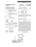
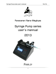
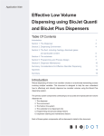
PHM-109 INTRACRANIAL PUMP
USER’S MANUAL
PHM-109 Head Pump Manual
DOC-042
Rev. 1.1
Copyright © 2008
All Rights Reserved
Med Associates, Inc.
P.O. Box 319
St. Albans, Vermont 05478
www.med-associates.com
MED ASSOCIATES INC.
PHM-109 INTRACRANIAL PUMP
- ii -
MED ASSOCIATES INC.
PHM-109 INTRACRANIAL PUMP
TABLE OF CONTENTS
Chapter 1 .............................................................................................. 1
Introduction ...................................................................................................... 1
Warnings and Cautions .................................................................................... 1
Chapter 2 .............................................................................................. 2
Installation Instructions ...................................................................................... 2
Hardware Guide .............................................................................................. 2
Cable Guide ................................................................................................... 4
Installation Instructions ................................................................................... 5
J1 Jumper Settings .......................................................................................... 9
Volume Infused per Step ................................................................................ 10
Chapter 3 ............................................................................................ 11
Operating Instructions ...................................................................................... 11
Pump Travel ................................................................................................. 11
Loading the Pump ......................................................................................... 12
MED-PC Controlled Operation.......................................................................... 13
Priming the Pump ......................................................................................... 13
- iii -
MED ASSOCIATES INC.
PHM-109 INTRACRANIAL PUMP
- iv -
MED ASSOCIATES INC.
PHM-109 INTRACRANIAL PUMP
CHAPTER 1
Introduction
The PHM-109 Intra-Cranial Pump is a head-mounted nanoliter injection system for
delivering compounds directly into a rat brain. The pump is mounted on the animal’s
head and the animal can move freely, since a swivel supports the pump. The short
distance between the pump and the animal’s brain allows the system to deliver consistent
volumes. The PHM-109 pump is controlled by a stepper motor, and can be operated
either manually or through MED-PC ® .
It is important that this manual be read thoroughly prior to operating this equipment.
Warnings and Cautions
WARNING: The SG-216A cable supplies power to the pump when connected to
a MED-PC Output, therefore it is not necessary to use the 28 VDC Inverter
concurrently. Connecting the 28 VDC Inverter and the SG-216A cable to the
Pump Controller concurrently may cause equipment damage.
NOTE: It is recommended that the maximum number of steps per infusion be 200. The
pump will not function properly if this number of steps is exceeded, as it will reach the
end of its travel and may burn out the pump motor.
NOTE: If the jumper on the J1 connector inside the Pump Controller (Figure 2.15) is in
the 2.1 or 2.2 position, the pump will be operating at ½ or ¼ step. It is important to
note that the volume infused per step will decrease accordingly.
- 1 -
MED ASSOCIATES INC.
PHM-109 INTRACRANIAL PUMP
CHAPTER 2
Installation Instructions
Hardware Guide
Figure 2.1 - PHM-109 Pump
Figure 2.2 - Multi-Channel Commutator
Figure 2.3 - Pump Controller Front Panel
Figure 2.4 - Pump Controller Back Panel
- 2 -
MED ASSOCIATES INC.
PHM-109 INTRACRANIAL PUMP
Figure 2.5 - Swivel Assembly
- 3 -
MED ASSOCIATES INC.
PHM-109 INTRACRANIAL PUMP
Cable Guide
Figure 2.6 - Pump Controller Cable
Figure 2.7 - SG-216A Cable (Only Used if Controlling the Pump with MED-PC)
Figure 2.8 - 28 VDC Inverter (Only Used if Operating the Pump in Manual Mode)
- 4 -
MED ASSOCIATES INC.
PHM-109 INTRACRANIAL PUMP
Installation Instructions
1.
Install the Swivel Assembly (Figure 2.5) in the desired location on the animal
chamber.
2.
Remove the two screws and the retaining bar at the end of the swivel assembly,
shown in Figure 2.9.
Figure 2.9 - End of Swivel Assembly
3.
Place the Multi-Channel Commutator (Figure 2.2) in the slot at the end of the Swivel
Arm and reinstall the retaining bar and screws as shown in Figure 2.10.
Figure 2.10 - Multi-Channel Commutator Installed on the Swivel Arm
- 5 -
MED ASSOCIATES INC.
4.
PHM-109 INTRACRANIAL PUMP
Using the Controller Cable (Figure 2.6), connect the MOTOR CONNECTION port on
the Pump Controller (Figure 2.4) to the connectors on the Multi-Channel Commutator
indicated in Figure 2.11. The end of the controller cable that connects to the
Commutator has two connectors, one white and one red. The red connector should
be plugged in to the red port on the Commutator, indicated in Figure 2.11 and white
to white. The connectors are also marked with black lines that indicate how the pins
of each connector should align.
Figure 2.11 - Connect to MOTOR CONNECTION
5.
Connect the cable that extends from the PHM-109 pump, shown in Figure 2.12, to
the connectors on the Multi-Channel Commutator indicated in Figure 2.13. Again, the
red connector plugs into the red port and the white connector into the white port.
The black lines indicate proper pin orientation.
Figure 2.12 - PHM-109 Pump Cable
- 6 -
MED ASSOCIATES INC.
PHM-109 INTRACRANIAL PUMP
Figure 2.13 - Connect to PHM-109 Pump Cable
- 7 -
MED ASSOCIATES INC.
PHM-109 INTRACRANIAL PUMP
If Controlling the Pump with MED-PC
WARNING: The SG-216A cable supplies power to the pump when connected to
a MED-PC Output, therefore it is not necessary to use the 28 VDC Inverter.
Connecting the 28 VDC Inverter and the SG-216A cable to the Pump Controller
concurrently may cause equipment damage.
6.
Using the SG-216A cable (Figure 2.7), connect the MED INPUT connector on the
pump controller (Figure 2.4) to a MED-PC Output.
If Operating Pump in Manual Mode
6.
Connect the 28 VDC Inverter (Figure 2.8) to the EXTERNAL POWER connector on
the Pump Controller (Figure 2.4). The pump is now ready to operate.
Figure 2.14 - Completed PHM-109 Pump Assembly
- 8 -
MED ASSOCIATES INC.
PHM-109 INTRACRANIAL PUMP
J1 Jumper Settings
Figure 2.15 - J1 with Jumper in the 1.1 Position
The J1 connector inside the Pump Controller (Figure 2.15) has a pin jumper whose
position can change the function of the pump based on the needs of the user. The top
four sets of pins (1.1, 1.2, 1.4 and 1.8 reading down the left in Figure 2.15) control the
pump speed when operating in manual mode.
The jumper position and the
corresponding speed, in steps per second, are as follows:
Jumper Position
No Jumper
1.1
1.2
1.4
1.8
Step Size
0.5
1
2
4
8
The set of pins labeled “Agnd” are not used. The bottom two sets of pins (2.1 and 2.2
reading down the left in Figure 2.15) control the step size of the motor. The jumper
position and corresponding step size are as follows:
Jumper Position
No Jumper
2.1
2.2
Step Size
Full Step
½ Step
¼ Step
- 9 -
MED ASSOCIATES INC.
PHM-109 INTRACRANIAL PUMP
Volume Infused per Step
When controlling the pump with MED-PC the user can control the number of motor steps
per infusion. The PHM-109 Intracranial Pump infuses approximately 23 nanoliters per
step.
However, it is advisable that each pump be validated prior to use.
The
recommended method for validation is as follows:
1.
Except for a 2-mm air space, fill a length of tubing with a colored liquid (water
colored with blue vegetable dye for example) and attach it to the tip of the
syringe needle. The 2 mm air space should be placed at the start of the line.
The inner diameter of the tubing must be known.
2.
Calculate the volume contained in 1 cm (10 mm) of tubing.
Inner Diameter / 2 = r ( Inner Radius )
Volume of a Cylinder =
π
r2 L
Where L is the length of tubing, which is 1 cm in this case. For example, if tubing with
an inner diameter of 0.58 mm is being used, then:
0.58 mm / 2 = 0.29 mm = r
Volume contained in 1 cm (10 mm) of tubing = 3.14
x
0.29 2
x
10 = 2.64 µl
3.
Operate the pump for a known number of steps and measure the distance that
the air space travels. Record the distance and repeat at least ten times.
4.
Average the distance traveled for each trial.
5.
Calculate the average volume per step by converting the average distance
traveled to cm. Then, multiply that number by the volume per cm of the tubing.
This gives the average volume infused. Divide this number by the number of
steps, and this is the average volume per step. For example, if the pump is run
for 50 steps and the average mm traveled is 4.47 the calculation will go as
follows:
Average Distance Traveled = 4.5 mm = 0.450 cm
Average Volume Infused = 0.450 cm x 2.640 µl/cm = 1.188 µl
Average Volume per Step = 1.188 µl / 50 steps = 0.024 µl/step
So for the pump in this example, the average volume per step is 0.024
microliters, or 24.0 nanoliters.
NOTE: If the jumper on the J1 connector inside the Pump Controller (Figure 2.15) is
in the 2.1 or 2.2 position, the pump will be operating at ½ or ¼ step. It is
important to note that the volume infused per step will decrease accordingly.
- 10 -
MED ASSOCIATES INC.
PHM-109 INTRACRANIAL PUMP
CHAPTER 3
Operating Instructions
Pump Travel
Because of the PHM-109’s compact size, the amount of volume that can be infused in a
single injection is limited. It is recommended that the maximum number of steps per
infusion be 200. Exceeding this number of steps may cause the pump to reach the end
of travel, which may cause damage to the pump motor.
Care should be taken to ensure that the pump is at the beginning of travel prior to
starting an infusion, as shown below in Figure 3.1. When the pump reaches the end of
travel, shown in Figure 3.2, it should be disconnected from the animal and primed (see
the Priming the Pump section of this manual).
Figure 3.1 - Beginning of Pump Travel
Figure 3.2 - End of Pump Travel
- 11 -
MED ASSOCIATES INC.
PHM-109 INTRACRANIAL PUMP
Loading the Pump
Figure 3.3 - Pump Assembly
Before each session the injector tubing and the pump canister must be filled with the
infusion solution. Fill the injector tubing assembly by connecting a 1 cc syringe filled
with the infusion solution. Inject the infusion solution into the injector tubing, being sure
that there are no air bubbles present. The pump canister can be filled by inserting the
needle tip of the syringe into the syringe needle of the pump canister, while holding the
canister vertically, syringe needle end down. Next, carefully connect the injector tubing
to the syringe needle of the pump canister. The canister can now be connected to the
threaded plunger by turning the manual motor knob 1-2 full revolutions, being sure that
the guide screw is in the alignment channel.
Before connecting the pump to the animal, it is recommended that the pump be run,
either using the MANUAL OPERATION button on the Pump Controller or by using MED-PC
to step the motor, until there is fluid at the end of the injection cannula (see the Priming
the Pump section of this manual).
Next remove the dummy cannula from the guide
cannula and connect the PHM-109 Intracranial Pump to the animal.
- 12 -
MED ASSOCIATES INC.
PHM-109 INTRACRANIAL PUMP
MED-PC Controlled Operation
The PHM-109 Intracranial Pump can be controlled easily using MED-PC.
program is shown below:
S.S.1,
S1, \ A is
#K1: SET
#K2: SET
#K3: SET
the
A =
A =
A =
number
50, b=
100, b
150, b
A sample
of steps per infusion
0 ---> S2
= 0 ---> S2
= 0 ---> S2
S2,
0.50": ADD B; ON 1 ---> S3
S3, \ one step will take 500 ms
0.50": OFF 1; IF B >= A [@End, @Cont]
@End: ---> S1
@Cont: ---> S2
In the example above the pump can be run at either 50, 100 or 150 steps. Each step will
last five hundred milliseconds.
NOTE: It is recommended that the maximum number of steps per infusion be 200. The
pump may not function properly if this number of steps is exceeded.
It should also be noted that the setting of the MOTOR DIRECTION switch (Figure 2.3) on
the Pump Controller is not recognized when the pump is being controlled by MED-PC.
Priming the Pump
The Manual Operation function of the PHM-109 Intracranial Pump is intended to be used
only for the purposes of priming the pump and tubing. It is not possible to accurately
calculate the volume infused when operating manually. The 28 VDC Inverter must be
connected to the Pump Controller in order for the pump to function in Manual mode.
NOTE: The SG-216A cable supplies power to the pump when connected to a
MED-PC Output, therefore connecting the 28 VDC Inverter and the SG-216A
cable to the Pump Controller concurrently may cause equipment damage.
To operate the pump manually, simply press the MANUAL OPERATION button (Figure
2.3). The pump will operate for as long as this button is held down. The direction of the
pump can be changed using the MOTOR DIRECTION switch (Figure 2.3).
- 13 -