1
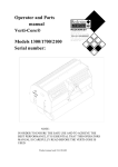
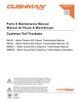
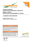
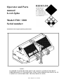
Operator and Parts
manual
Level-Spike
Model 1700 / 2200
Serial number:
Translation of the original operating instructions
NOTE:
IN ORDER TO ENSURE THE SAFE USE AND TO ACHIEVE THE BEST
PERFORMANCE, IT IS ESSENTIAL THAT THIS OPERATORS MANUAL IS
CAREFULLY READ BEFORE THE MACHINE IS USED.
0948 English 913.120.402
FOREWORD
Congratulations on the purchase of your Redexim- Charterhouse LEVEL-SPIKE. To ensure the safe
and lasting operations of this LEVEL-SPIKE you (and anyone using the machine) should read and
understand this user’s manual. A complete knowledge of the contents of the manual is necessary in
order to ensure the safe use of this machine.
The LEVEL-SPIKE is not an independently operating machine. It is the responsibility of the user to use
the correct tractor. The user will also need to check the tractor / LEVEL-SPIKE combination on safety
aspects, noise level, user instructions and risk assessment.
The LEVEL-SPIKE is intended exclusively for grass fields or areas on which grass can grow.
On the following page, we will begin with the safety instructions. Every user must be familiar with
these instructions and must follow them carefully. Attached and below you will find a registration card,
which should be returned to us so that we are able to process any future claims.
In this manual, many instructions are given which are stated in a number sequence. The user must
follow the instructions according to this sequence. If the * appears this refers to safety instructions. If
the @ is used, this refers to a tip and/ or note.
All information and technical specifications provided at the moment that this document is published are
the most recent ones. Design specifications may be changed without prior notice.
This document is a translation of the original operating instructions.
Upon request, the original operating instructions are available in Dutch.
GUARANTEE CONDITIONS
THIS MULTI-SPIKE PRODUCT IS DELIVERED TO THE CUSTOMER ACCOMMPANIED BY A
GUARANTEE AGAINST DEFECTS IN THE MATERIALS USED. THIS GUARANTEE APPLIES
FOR A PERIOD OF 12 MONTHS AS OF THE DATE OF PURCHASE.
Redexim- Charterhouse GUARANTEES ARE SUBJECTED TO THE "GENERAL CONDITIONS
FOR SUPPLY OF PLANT AND MACHINERY FOR EXPORT, NUMBER 188", WHICH ARE
PUBLISHED UNDER THE AUSPICES OF THE UNITED NATIONS ECONOMIC COMMISSION
FOR EUROPE.
REGISTRATION CARD
For your own record, copy the information from the registration card to the table hereunder. Mail the
attached card back to us.
Serial number of machine
Name of your distributor
Date of purchase
Any remarks
2
SAFETY INSTRUCTIONS
1.
Always use the MULTI-SPIKE with the correct tractor as described in the
technical information
2.
The user is responsible for a safe Tractor/LEVEL-SPIKE combination. The
combination must be tested for noise, safety, risk and easy usage. It is also necessary to
draw up user instructions.
3.
The LEVEL-SPIKE is suited exclusively to grass fields.
4.
Every LEVEL-SPIKE user must be fully informed of the information contained in the
user manual.
5.
Inspect the ground where the LEVEL-SPIKE is to be applied. Remove loose
obstacles, avoid uneven ground.
6.
Never step off the tractor if the engine is still running.
7.
Ensure that other people are standing at least 4 mtr. (14' ) away from the LEVELSPIKE
8.
Use appropriate clothing. Wear strong shoes with a steel enforced toe cap, long
trousers, tie up long hair. Do not have any loose pieces of clothing.
9.
Never try to force the LEVEL-SPIKE, a situation which is visible in unstable
behavior of the MULTI-SPIKE.
10.
Check the LEVEL-SPIKE once a week to ensure there are no loose screws or nuts and
bolts.
11.
The LEVEL-SPIKE may never be used without protection covers and safety stickers.
12.
NEVER crawl underneath the LEVEL-SPIKE. If you need to work underneath, turn
the LEVEL-SPIKE on its front.
13.
Always switch off the engine, before starting any maintenance, adjustment or repair.
Also block the LEVEL-SPIKE against sinking and block it against forward/backward
movement or sliding.
14.
Use only the original LEVEL-SPIKE spare parts/ tines in order to ensure the safe
operation of the machine.
15.
Never use the LEVEL-SPIKE in the dark, in heavy rain, on frozen ground, stormy
conditions or on slopes greater than 20 degrees.
16.
Maintain a log book of repairs.
17.
If any modifications are carried out on the machine the CE certification mark will be
no longer valid. The User/Dealer himself must then have the machine re-certified.
3
CONTENTS
Par.
Description
Page
Foreword
2
Guarantee conditions
2
Registration card
2
Safety instruction
3
1.0
Technical specification
5
2.0
First setup
7
3.0
General controls
8
4.0
Working depth adjustment
9
5.0
Groundspeed
9
6.0
General usage of the Level-Spike
10
7.0
Transport of the Level-Spike
10
8.0
Uncoupling of the Level-Spike
10
9.0
Problem analyses
11
10.0
Maintenance
11
11.0
EU-Declaration
11
12.0
Options
12
12.1
Additional deep slit knife kit
13
12.2
Fine slit knife kit
13
12.3
Truckster knife kits
14
12.4
Hollow tine kit
14
12.5
Rear roller kit
15
12.6
Weight transfer kit
16
4
1.0 TECHNICAL SPECIFICATIONS
Model
1700
2200
Working width
1800 mm (72”)
2400 mm (96”)
Working depth
Up to 250 mm (10”)
Up to 250 mm (10”)
Weight
405 Kg (890 lbs)
495 Kg (1090 lbs)
Hole spacing side-to-side
75 mm (3”), with fine slit knives
75 mm (3”), with fine slit knives
150 mm ( 6”), with all other
knives/ tines
150 mm ( 6”), with all other
knives/ tines
Hole spacing in driving
direction,
With 3 knives/ disk: 440 mm(18”) With 3 knives/ disk: 440 mm (18”)
at maximum depth
center-to center
With 6 knives/ disk: 220 mm ( 9”) With 6 knives/ disk: 220 mm ( 9”)
With 4 knives/ disk: 330 mm( 13”) With 4 knives/ disk:330 mm ( 13”)
With 12 knives/disk:110 mm(4½”) With 12 knives/disk:110 mm(4½”)
Recommended minimum 35 HP with lift capacity of
tractor size
minimum 500 Kg ( 1100 lbs)
Capacity:
45 HP with lift capacity of
minimum 600 Kg ( 1300 lbs)
At 5 km/hour ( 3.1 mph) 9000 m² At 5 km/hour ( 3.1 mph) 12000
(81,000 sq ft)/hour
m² (108,000 sq ft)/hour
At 10km/hour (6.2 mph) 18000m² At 10km/hour (6.2 mph) 24000m²
(162,000sq.ft)/hour
(216,000sq.ft)/hour
At 15km/hour (9.4 mph) 27000m² At 15km/hour (9.4 mph) 36000m²
(244,000sq.ft)/hour
(324,000sq.ft)/hour
Shipping dimensions
1860 x 550 x 1400 mm
(74”x 22”x 56”) L x W x H
2470 x 550 x 1400 mm
(99”x 22”x 56”) L x W x H
Three point linkage
3- point CAT 1 & 2
3- point CAT 1 & 2
Lubrication grease
EP 2
EP 2
Standard items
Deep slit knife kit ( 4 per disk)
Deep slit knife kit ( 4 per disk)
Manual
Manual
Support jack
Support jack
5
6
2.0 FIRST SETUP
The machine is delivered on a pallet. To install the machine behind a tractor, handle as follows (see
fig.1, 2, 3, 4, 5 and 6 )
1. Remove all boxes from the machine, which contain knives, bearings, safety bars, bolts/nuts and a
jack.
2. Firmly connect a sling 2 of approximately 3.5 mtr (11 ‘) with D- shackles to the holes 1 at each side
of the machines as shown in Fig.1.
3. Lift the machine slowly. Be aware that the machine may be unstable during the tip over, however it
will not drop on the ground.
4. Lay the machine horizontal on a flat floor, as shown in Fig.2.
5. Remove the two bolts 5 that hold the main rotor. Check that the main rotor lays on the ground.
When both bolts 5 are out, the rotor can be rolled back till it is in position 6.
6. Slowly lift the machine again, see Fig.3., till the rotor can be rolled away.
7. The deep slit knives ( standard delivered with machine), can be mounted on the rotor, as shown in
Fig.4. In Fig.4. four knives are evenly fitted at a disk. On the next disk, the knives should be
mounted with an offset. In Fig.4 this is indicated with a number on the knives. One means the first
disk etc. Mount the knives exactly the same way as drawn in Fig.4. For more information on knives
and the assembly, see Chapter 12.
8. Lower the machine back on the ground. Remove the Pallet and connect the machine to a tractor.
(Leave the rear roller fixed).
9. Lift the unit with the tractor as much as possible. Shorten the toplink when necessary. Roll the rotor
with mounted knives under the machine. Assemble the rotor bearing on the rotor ends and use the
bolts/ washers 14 and nuts to firmly mount the rotor to the main frame. When everything fits well,
tighten the grub screw of the bearings.
10. The last items to assemble are the safety bars 17, that are identical. They should be on. Use two
bolts/ nuts at each side.
11. Slide the jack 13 upside down on and lock it with the lock pin.
•
Be very careful during all operations and do not take any unsafe steps.
•
Be aware of the knives during handling. They are sharp and can seriously hurt you. Stay away
with your hands and feet as much as possible. Use protection gloves.
•
If you prefer, you can exchange or mount the knives, via the top cover gaps. Mount the rotor
first in the unit, remove the two front or rear covers and assemble the knives from the top.
LOCK the machine.
@ If the tractor can’t lift high enough, use the sling again or assemble the knives afterwards, see above.
@ The position of the blades at the rotor and the position of the rotor in the main frame is critical for the
final job done. So check this carefully with the figures 1 to 6 and Chapter 12.
7
3.0 GENERAL CONTROLS
In fig.2. some key details of the machine are shown, as follows:
1. Hook up points or securing points when weights are added.
2. Area for extra weights. NOTE. The maximum load applied may not exceed 400 Kg (880 lbs).
3. Safety decal RB and RC. Keep 4 mtr (14’) distance to the machine/ Turn engine off when
maintaining or repairing the machine.
4. Safety bar at each side of machine. Should be on all the time
5. Manual box with manual enclosed and safety decal RA: Read manual before using machine.
6. Serial number plate.
7. Cat. 1 & 2 bottom link pin.
8.
Jack for supporting and securing machine during storage and repair.
9. Pin to lock jack to machine. Jack can be reversed when fixed to a tractor.
10. Cat 2 top link pin.
Fig.7.
11. Bolts/ nuts/ washers for keeping safety covers in place.
8
4.0 WORKING DEPTH ADJUSTMENT
The rear roller is an option for the LEVEL-SPIKE 1700 & 2200, see chapter 12. In case the rear roller is
added, the depth can be regulated.
The working depth can be set by locking the rear roller supports 3 with pin 2 at a certain level. When
the machine is at 90 degrees behind the tractor, the depth D is maintained. The lock pin is a coarse
setting. The fine tuning can be done with the top link of the tractor. If the rear roller has to float, store
the lock pin 2 in hole 4.
@ The rear roller locking may ONLY be used when no Weight Transfer System or extra weights are
used. Otherwise serious damage may appear.
@ The rear roller may be locked for storage as well, however only when the roller rests ON the ground.
If that does not happen the machine may tip.
@ Use the 90 degrees setting always as the starting point.
9
5.0 GROUNDSPEED
The forward speed during work, should be limited till 15 km/hour ( 9.4 mph). Faster is not allowed. The
faster we go, the less time a knife has for penetration. So working slower may give a better result in the
end. This depends on the soil as well.
@ Make only straight passes with a 3-point linkage model.
@ The unit can be lowered into the ground and raised without stopping the tractor.
* Be aware that the rotor may continue to run when raised during forward motion. Don’t come close to
the machine, but drop it first in the ground to stop
90
D
6.0 GENERAL USAGE OF THE LEVEL-SPIKE
The LEVEL-SPIKE can only be used when the circumstances are right. Check the following items:
1. Are there any loose objects on the field. If so, these must be removed first.
2. Are there any slopes. The maximum slope for the LEVEL-SPIKE is 20 degrees. Always operate the
LEVEL-SPIKE from the top to the bottom of a slope.
3. Are there any pipes/wires/cables in the ground. If so, ascertain at what depth and set the working
depth at a maximum of 60% of the pipe etc. depth.
4. Are there any hard objects in the ground. If so, operate the LEVEL-SPIKE with a very low speed, or
adjust working depth.
5. Is there any danger of flying objects such as golf balls, which could distract the attention of the
driver ? If so, the LEVEL-SPIKE can not be operated at that moment.
6. Is there any danger of subsidence or land/mud slides ? If so, the LEVEL-SPIKE cannot be operated
on the field at that moment.
7. Is the ground frozen or very wet. Postpone operation till circumstances are better.
10
7.0 TRANSPORT OF THE LEVEL-SPIKE
The user is responsible for the transport of the LEVEL-SPIKE behind the tractor along the public
streets. Check on the national legislations. Across open ground a maximum speed of 20 km/h (13 mph)
applies. In view of the weight of the LEVEL-SPIKE, a higher speed could be dangerous for the driver
and bystanders. The machine could also suffer damage due to jolt which can occur with higher speeds.
* At least 20% of the tractor weight should rest on the front axle when machine is lifted.
8.0 UNCOUPLING OF THE LEVEL-SPIKE
The machine can be disconnected from the tractor as follows,
1. Look for a flat area.
2. Lock the rear roller in bottom position, or leave it free floating (when mounted).
3. Reverse the jack.
4. Gently lower the machine with the knives on the ground.
5. Drop the jack, till the machine is well supported.
6. Remove the top link
7. Remove the bottom link.
•
The area needs to be level.
•
Additional weight has to be taken off first..
9.0 PROBLEM ANALYSIS
Slits/ holes are badly
shaped
Wrong type of knife
Use other type
Weak soil
Reduce working depth
Use other type of knife
Knives at wrong position
Check correct position
Try other position
10.0 MAINTENANCE
Pre-Delivery-Inspection
Check bolts/ nuts
Connect the unit to a tractor
Mount the tines/ knives
See instructions in this
manual
See Chapter 2 and 12
Weekly
Clean machine
After first 20 hours
Grease rotor and roller
bearings
(new or repaired)
2 shots each EP 2
Check bolts/nuts
11
After every 100 hours
Grease rotor and roller
bearings.
2 shots each EP 2
Check bolts/ nuts
11.0 EU-Declaration.
We, Redexim Utrechtseweg 127 3702 AC Zeist Holland, hereby declare fully on our authority that the
product:
LEVEL-SPIKE 1700/ 2200, WITH SERIAL NUMBER AS INDICATED ON THE MACHINE AND
IN THIS MANUAL,
to which this declaration relates is according to the stipulation of the 2006/42/EC directive for
machines.
Zeist, 01/10/09
A.C. Bos
Manager Operations & Logistics
Redexim Holland
12
12.0 OPTIONS (see fig.8.)
Standard the LEVEL-SPIKE 1700 & 2200 are delivered with a set of deep slit knives ( 4 per disk)
Basically, depending on the knife or tine size, we can mount 3,4,6 or 12 knives evenly per disk. With
the standard kit, we can mount 4 per disk, as is shown in Fig.8. It is important to mount the knives in
the holes as shown in Fig.8. Use bolt 3 and nut 1. In the figure the preferred rotation direction is given
as well. Be aware that the rotor is mounted correctly in the main frame, so the rotation direction works
out well.
@ In almost all cases the LEVEL-SPIKE is towed behind a tractor. However in case the unit is pushed,
the rotor should be reversed.
@ Under some conditions, the knives may do a better job when reversed. The best way to try is
reversing the drive direction and look at the results. If the results are better, reverse the rotor in the
main frame.
@ The more knives/ tines are assembled, the closer the pattern. However the more weight is needed for
penetration either. So if you require depth, use less knives.
@ The disks are welded offset to each other, so we can create a spiral ( 4 in Fig.11.), which makes the
machine run smoother. Be aware of this when more knives are added.
@ Changing or adding knives/ tines can be done in two ways:
1. Remove the whole rotor and change/ add knives, see instructions in Chapter 2.
2. Remove the covers, see # 15 in Fig.7, and work from the top
•
Be aware of sharp items. Work carefully. Secure the machine all the time with the jack
•
Never crawl under the machine or rotor
•
Always secure the rotor from rolling away.
13
12.1 ADDITIONAL DEEP SLIT KNIFE KIT (see fig.9)
In case you want to use 6 Deep slit knives per disk, instead of the 4 we standard deliver, an additional
kit (# 213.170.012 for 1700 and 213.220.012 for 2200) is available, that contains 24/ 32 more deep slit
knives with bolts and nuts.
When 6 deep slit knives per disk are used, it is important to mount them the same way as drawn in
Fig.9. Use the holes as given in Fig. 8.
12.2 FINE SLIT KNIFE KIT ( See fig.10)
The fine slit knives fit on the same rotor. Distance bushes are used to offset the knives from the disks,
see Fig.10. Each disk can take up to 12 fine slit knives per side. It is important to know that on both
outer disks, we can not assemble fine slit knives at the outer side. The fine slit knife kit (# 213.170.008
for the 1700 and # 213.220.008 for the 2200) contains respectively: 264/ 360 fine slit knives (1), 528/
720 distance bushes (4,5 & 8), 264/ 360 long bolts (6), 48/ 48 short bolts (9) and 312/ 408 nuts (3).
They should be assembled as drawn in Fig.10. As described previously, more options are possible. E.g.
use 6 double row fine slit knives, or 12 at a single row per disk ( no distance bushes needed).
@ If the customer often switches from one type of knife to the other, it is maybe worth buying another
standard rotor and exchange rotors instead of knives.
@ Check the bolts and nuts regularly.
@ Exchange bent knives immediately.
14
12.3 TRUCKSTER KNIFE KITS (See fig. 11 and 12)
Truckster slit knives fit to the Level-Spike 1700 / 2200 as well. The standard kit (# 213.170.004 for the
1700 and # 213.220.004 for the 2200) contains respectively : 48/ 64 truckster knives (1), 96/ 128 bolts
(2) and 96/ 128 nuts (3).`They should be assembled as drawn in Fig.11.
If you want to add more truckster knives, an additional truckster knife kit (# 213.170.006 for the 1700
and # 213.220.006 for the 2200) is available, which is half the size of standard kit above. This means
that when added, we can increase the number of knives per disk from 4 to 6, as drawn in Fig. 12.
When 6 truckster knives are used per disk, it is important to mount them the same way as drawn in fig
12, three at one side and three at the other side of the disk.
12.3 HOLLOW TINE KIT ( See fig.13)
A Hollow tine kit ( # 213.170.014 for the 1700 and 213.220.014 for the 2200) is available for the
standard rotor. The kit contains respectively: 72/ 96 x Hollow tine (2), 144/ 192 x nut (3) and 144/ 192 x
bolt (4).
Assemble them as is drawn in Fig. 13. Divide them even around the disks. If you want to use 12 per
disk, simply order another kit .
@ Don’t use extra weight, the tines may collapse.
@ If the holes do not look well, reduce the working depth.
@ It is normal that they may fit a bit tight. Use a small (plastic) hammer.
15
12.5 REAR ROLLER KIT, See fig.14.
A rear roller kit ( # 213.170.002 for the 1700 and # 213.220.002 for the 2200) is available for both
LEVEL –SPIKES. In Fig.14. the assembly of the rear roller is given, which is straight forward. The rear
roller can float or set at a certain position. Please take notice of chapter 4.0, in which some notes are
given, related to the use of the rear roller.
16
Fig.15.
12.6 WEIGHT TRANSFER KIT, See fig.15.
With the weight transfer kit, extra weight from the tractor can be transferred to the spiker for better
penetration. The maximum allowable weight transfer may not exceed 2000 Kg., because the machine
may get hurt or dangerous situations may occur.
A four wheel driven tractor is recommended when a weight transfer kit is used, since the weight on the
rear wheels is reduced.
PREPARATIONS.
Assemble the components to the hydraulic cylinder, see Fig. 15. The flow reducer 2 is screwed in the
hydraulic cylinder 10. Use copper washer 3. Fit all three connectors 5 to the pressure relieve valve 7,
using washers 3. Slide the tubes 4/8 fully into the connectors 5, T connector 1 and screw able connector
11. Mount everything onto the cylinder ports. When everything fits, tighten all connectors, keeping the
valve 7 vertical up. Next hoses 9 can be fitted to the connectors 1 and 5. At the other end of the hose a
threaded nipple 12 fits, on which a quick Fit connector 14 can be mounted, using a copper washer 13 to
seal. When everything is tight, the hydraulic cylinder assembly is ready to use.
Fit the symmetric plates 31 with bolts 30 and nuts 34 to the standard holes 35 of the machine, as is
shown in fig. 15.
Remove the toplink pin 27, in order to create some more space and to prevent the pin from damaging the
beam 21.
Mount the machine to the tractor, using the bottom link arms 20 only. When connected, remove the jack (
and fit in upside down to the machine) and lower the machine till size A = approximately 300 mm ( 12”).
NEXT, SECURE THE MACHINE IN THE CENTER OF THE TRACTOR WITH THE
STABILISATORS OF THE TRACTOR. This is very important. Assemble the two plates 21 with pin 25
to the machine. Secure it with linch pin 26. Fit beam 16 with hole 15 to the top link connection of the
17
tractor. Slide beam 16 between the two plates 21 and check whether a hole 24 lines up. If yes fit BOTH
bolts 22 and tighten them with nut 19. If not, lower or raise the machine a little till the first hole matches.
When BOTH bolts 22 are secured, lower the 3-point activating lever inside the tractor to the lowest
position. The machine fixed to the tractor at the correct position.
The bottom end of the hydraulic cylinder can be mounted to beam 15, using as a start hole 17. Use a bolt
23 and nut 19A. Do NOT tighten the nut tight. At the rod side the hydraulic cylinder can be connected to
one of the holes 32 of plate 31. Use pin 33 with two distance bushes 36 at each side of the rod end.
Basically the unit is ready for use, BUT READ FIRST the important notes here under.
IMPORTANT NOTES.
-
Be very careful the first time of use. Check whether the hydraulic cylinder does not hit the machine
and/or the central beam 15/22 gets stuck.
-
If the side stabilization of the bottom links is not set tight and in the center, serious damage may
occur.
-
Choose the correct hole 32. The starting point is that the machine has to be horizontal when the
hydraulic cylinder is fully out. Do not overturn the machine any further. Damage may occur,
specially when a rear roller is fitted. Check this in the field, when the machine is pushed in the
ground.
-
When the hydraulic cylinder is fully in, the machine is raised from the ground.
-
Check the clearances of the hydraulic cylinder carefully when fully out, carefully. If not enough
clearance is available (specially with small tractors), the hydraulic cylinder bottom end may be
moved up towards hole 18. If still not enough space is available, drop the starting height A from 300
to 250mm(10”)
-
Height A from 300 to 250mm (10”).
-
When a rear roller is fitted, it should be in the free float position all the time Never secure the rear
roller for a certain working depth.
-
Disconnecting the weight transfer kit goes the other way round.
-
If next time another tractor is used, the procedure should be started again. If not, the standard set
main secure beam can stay at the same length.
SAFETY ITEMS.
•
Never crawl under the machine.
•
Be careful in assembling the different items. Do not stand between the machine and tractor.
•
Since the machine tips forwards, sharp knifes/ tines are accessible from the rear. So for that
reason, the weight transfer has to be removed and exchanged for a normal toplink, after
the job is done. Only when a rear roller is assembled, the machine is protected well enough
from the rear.
•
The pressure setting of valve 7 has to be carefully set, so that the tractor’s rear wheels are
NOT lifted from the ground. If not done, dangerous situations may occur. This setting, via
screwing bolt 6 in or out, has to be repeated when another tractor is used.
•
Be aware of high oil pressure. Do not touch any leakages by hand. Also be aware of pressure
build up during work in the hydraulic cylinder.
•
NEVER touch the 3- point activating lever inside the tractor. It should stay in the
lowest position ALL the time. Serious damage to tractor and machine may occur when the lever
is moved.
•
Maximum oil pressure allowed on the system is 180 bar (2500psi)
18