1
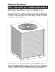
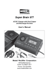
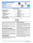
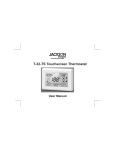
Outdoor Air Conditioner
User’s Information and Installation Instructions
10 SEER Standard Efficiency Split System
These instructions are primarily intended to assist qualified individuals experienced in the proper
installation of heating and/or air conditioning appliances. Some local codes require licensed
installation/service personnel for this type of equipment. Read all instructions carefully before
starting the installation.
These units have been designed and tested for
capacity and efficiency in accordance with ARI
Standards. Split System Air Conditioning units
are designed for use with a wide variety of fossil
fuel furnaces, electric furnaces, air handlers,
and evaporator coil combinations.
USER’S INFORMATION
IMPORTANT
Read this owner information to become familiar
with the capabilities and use of your appliance.
Keep this with literature on other appliances
where you have easy access to it in the future. If
a problem occurs, check the instructions and
follow recommendations given. If these
suggestions don’t eliminate your problem, call
your servicing contractor.
OPERATING INSTRUCTIONS
To Operate Your Air Conditioner
for Cooling —
1. Set the thermostat system switch to COOL
or AUTO and the thermostat fan switch to
AUTO. (See Figure 1)
2. Set the thermostat temperature to the
desired temperature level by using the
temperature selector. Please refer to the
separate detailed thermostat user's manual
for complete instructions regarding
thermostat programming. The outdoor
unit and indoor blower will both cycle on
and off to maintain the indoor temperature
at the desired cooling level.
2. Set the thermostat temperature to the
desired temperature level by using the
temperature selector. Please refer to the
separate detailed user's manual for
complete thermostat programming
instructions. The furnace and indoor blower
will cycle on and off to maintain the indoor
temperature at the desired heating level.
To Shut Off Your Air Conditioner —
Set the thermostat system switch to OFF and the
thermostat fan switch to AUTO. (See Figure 1)
The system will not operate, regardless of the
thermostat temperature setting.
To Operate the Indoor Blower
Continuously —
Set the thermostat fan switch to ON (See Figure 1)
The indoor blower will start immediately, and will
run continually until the fan switch is reset to
AUTO.
The continuous indoor blower operation can
be obtained with the thermostat system switch
set in any position, including OFF.
SYSTEM SWITCH
FAN SWITCH
To Operate Your Furnace
for Heating —
TEMPERATURE SCALES
1.
Set the thermostat system switch to HEAT
or AUTO and the thermostat fan switch to
AUTO. (See Figure 1)
TEMPERATURE
SELECTOR
Figure 1. Typical Thermostat
The continuous indoor blower operation is
typically used to circulate the indoor air to equalize
a temperature unbalance due to a sun load,
cooking, or fireplace operation.
Read Your Warranty
Please read the separate warranty document
completely. It contains valuable information
about your system.
To Maintain Your Air Conditioner —
! CAUTION:
Be certain the electrical power to the
outdoor unit and the furnace/air handler
is disconnected before doing the
following recommended maintenance.
1.
Regularly:
a. Clean or replace the indoor air filter at the
start of each heating and cooling season,
and when an accumulation of dust and dirt
is visible on the air filter.
b. Remove any leaves and grass clippings
from the coil in the outdoor unit, being
careful not to damage the aluminum fins.
c. Check for any obstruction, such as twigs,
sticks, etc.
! CAUTION:
Do not over-oil, or oil motors not factoryequipped with oil tubes. The compressor
is hermetically “sealed” and does not
require lubrication.
2.
Before Each Cooling Season:
If the furnace/air handler blower motor and
the outdoor unit fan motor(s) have oil tubes
at the motor bearings, apply 10 drops of
SAE No. 20 motor oil to each oil tube.
3.
Before Calling a Service Technician, Be
Certain:
a. The unit thermostat is properly set — see
“To Operate Your Air Conditioner for
Cooling” and “To Operate Your Furnace
for Heating.”
b. The unit disconnect fuses are in good
condition, and
the electrical power to the unit is turned on.
2
1. GENERAL INFORMATION
Read the following instructions completely before
performing the installation.
Condensing Unit Section — Each condensing
unit is shipped with a refrigerant charge adequate
to operate the outdoor section with an indoor
matching coil or air handler and 15 feet of
refrigeration line.
NOTE: DO NOT USE ANY PORTION OF THE
CHARGE FOR PURGING OR LEAK TESTING.
Liquid and Suction Lines — Refrigerant grade
copper tubing should be used when installing
the system. Refrigerant suction line tubing
should be fully insulated to prevent condensate
damage.
Field Connections for Electrical Power Supply
— All wiring must comply with the current
provisions of the “National Electrical Code” (ANSI
C1.) and with applicable local codes having
jurisdiction. Size of electrical conductors and
circuit protection must be in compliance with the
information listed on the outdoor unit data label.
2. SAFETY CONSIDERATIONS
Pressures Within the System — Split System
Air Conditioning equipment contains liquid and
gaseous refrigerant under pressure. Installation
and servicing of this equipment should be
accomplished by qualified, trained personnel
thoroughly familiar with this type of equipment.
Under no circumstances should the homeowner
attempt to install and/or service the equipment
without proper supervision from trained and
qualified service personnel.
! WARNING:
Ensure all electrical power to the unit is
off prior to installing or servicing the
equipment. Failure to do so may cause
personal injury or death.
Labels, Tags, Precautions — When working
with this equipment, follow all precautions in
literature, on tags, and on labels provided with
the equipment. Read and thoroughly understand
the instructions provided with the equipment
prior to performing the installation and operational
checkout of the equipment.
Cantilever Mount — The cantilever mount
should be designed with adequate safety factor
to support the weight of the equipment, and for
loads the mount is subjected to during operation.
Installed equipment should be adequately
secured to the cantilever mount and levelled
prior to operation of the equipment.
3. SITE PREPARATION
Roof Mount — The method of mounting should
be designed so as not to overload roof structures
nor transmit noise to the interior of the structure.
Refrigerant and electrical lines should be routed
through suitably waterproofed openings to
prevent water leaking into the structure.
Unpacking Equipment — Remove the
cardboard carton and Literature Package from
the equipment.
Inspect for Damage — Inspect the equipment
for damage prior to installing the equipment at
the job site. Ensure coil fins are straight and, if
necessary, comb fins to remove flattened and
bent fins.
Preferred Location of the Outdoor Unit at
the Job Site — Conduct a survey of the job
site to determine the optimum location for
mounting the outdoor unit. Overhead
obstructions, poorly ventilated areas, and
areas subject to accumulation of debris should
be avoided. The outdoor unit must be installed
in such a manner that airflow through the coil is
not obstructed and that the unit can be serviced.
Facility Prerequisites — Electrical power
supplied must be adequate for proper operation
of the equipment. The system must be wired and
provided with circuit protection in accordance
with local building codes and the National
Electrical Code.
Minimum Circuit Ampacity — Electrical wiring
to the equipment must be compatible and in
compliance with the minimum circuit ampacity
listed on the outdoor unit data label.
Maximum Fuse/Circuit Breaker Size — Circuit
protection for the outdoor unit must be compatible
with the maximum fuse/circuit breaker size listed
on the outdoor unit data label.
4. INSTALLING THE OUTDOOR UNIT
Slab Mount — The site selected for a slab
mount installation requires a stable foundation
and one not subject to erosion. The slab should
be level and anchored (if necessary) prior to
placing the equipment on the slab.
5. INSTALLING THE INDOOR UNIT
The indoor section of the unit should be installed
before proceeding with the routing of refrigerant
piping. Consult the Installation Instructions of
the indoor unit (i.e., air handler, fan coil unit,
etc.) for details regarding installation.
6. CONNECTING REFRIGERANT
TUBING BETWEEN THE INDOOR
AND OUTDOOR UNIT
General Information — Once the outdoor and
indoor unit placement has been determined,
route the refrigerant tubing between the
equipment in accordance with sound installation
practices. Refrigerant tubing should be routed
in a manner that minimizes the length of tubing
and the number of bends in the tubing.
Refrigerant tubing should be supported in a
manner that the tubing will not vibrate or abrade
during system operation. Tubing should be kept
clean of foreign debris during installation and
installation of a liquid line filter drier is
recommended if cleanliness or adequacy of
system evacuation is unknown or compromised.
Every effort should be made by the installer to
ensure that the field installed refrigerant
containing components of the system have been
installed in accordance with these instructions
and sound installation practices so as to insure
reliable system operation and longevity. The
maximum recommended interconnecting
refrigerant line length is 75 feet, and the vertical
elevation difference between the indoor and
outdoor sections should not exceed 20 feet.
Optional Equipment — Optional equipment
(i.e.: filter/driers, liquid line solenoid valves, etc.)
should be installed in strict accordance with the
manufacturer’s Installation Instructions.
3
For refrigerant line sets that incorporate single
shot couplings only:
1. Remove protective caps from the unit and
the refrigerant line couplings
2. Carefully wipe all coupling threads and
seals with a clean cloth to remove any dust
or foreign material which could contaminate
the refrigerant system.
3. Using refrigerant oil, lightly lubricate the
diaphragm, seal and threads on the male
unit coupling.
4. Connect couplings as follows:
a.
b.
HOLD REFRIGERANT LINE IN
STRAIGHT POSITION TO UNIT
COUPLING
AND
THREAD
COUPLING HALVES TOGETHER BY
HAND TO INSURE PROPER
CONNECTION. Hold body of the line
coupling hex, with wrench, while slowly
tightening the union nut until a definite
resistance (bottoming out) is felt.
Mark the position of union nut (match
lines on the line coupling and the unit bulk
head), and then tighten the coupling an
additional 1/4 turn to insure leak-proof
connection. (See Table of Torque Values
for recommended torque values if a torque
wrench is used.)
TABLE OF TORQUE VALUES
Coupling Size
3/8” (10 mm)
Liquid Line Coupling
Torque
10 - 12 ft. lbs.
(Metric: 14-16 N-m)
3/4” (19 mm) or
7/8” (22 mm)
Vapor Line Coupling
34-45 ft. lbs.
(Metric: 47-61 N-m)
Service Valve Cap
5-6 ft. lbs.
(Metric: 7-8 N-m)
7. MAKING ELECTRICAL
CONNECTIONS
! WARNING:
Turn off all electrical power at the
main circuit box before wiring
electrical power to the outdoor unit.
Failure to comply may cause severe
personal injury or death.
4
Wiring Diagram/Schematic — A wiring
diagram/schematic is located on the inside
cover of the electrical box of the outdoor unit.
The installer should become familiar with the
wiring diagram/schematic before making any
electrical connections to the outdoor unit.
Outdoor Unit Connections — The outdoor
unit requires both power and control circuit
electrical connections. Refer to the unit wiring
diagram/schematic for identification and location
of outdoor unit field wiring interfaces.
Control Circuit Wiring — The outdoor unit is
designed to operate from a 24 VAC control
circuit. Control circuit wiring must comply with
the current provisions of the “National Electrical
Code” (ANSI C1.) and with applicable local
codes having jurisdiction.
Thermostat Connections — Thermostat
connections should be made in accordance
with the instructions supplied with the thermostat
and with the instructions supplied with the
indoor equipment.
Electrical Wiring — Electrical wiring must
comply with the current provisions of the
“National Electrical Code” (ANSI C1.) and
with applicable local codes having jurisdiction.
Use of rain tight conduit is recommended.
Electrical conductors shall have a minimum
circuit ampacity in compliance with the
outdoor unit rating label. The facility shall
employ electrical circuit protection at a
current rating no greater than that indicated
on the outdoor unit rating label.
Disconnect Switch — An electrically
compatible disconnect switch must be within
line of sight of the outdoor unit. This switch shall
be capable of electrically de-energizing the
outdoor unit.
Optional Equipment — Optional equipment
requiring connection to the power or control
circuits shall be wired in strict accordance with
current provisions of the “National Electrical
Code” (ANSI C1.), with applicable local codes
having jurisdiction, and the Installation
Instructions provided with the equipment.
Optional Equipment (i.e., liquid line solenoid
valves, hard start kits, low suction pressure
cutout switch kit, high pressure cutout switch
kit, refrigerant compressor crankcase heater,
etc.) should be installed in strict accordance
with the manufacturer’s Installation Instructions.
8. START-UP AND CHECKOUT
! WARNING:
Ensure electrical power to the unit is off
prior to performing the following steps.
Failure to do so may cause personal
injury or death.
Air Filters — Ensure air filters are clean and in
place prior to operating the equipment.
Thermostat — Set the room thermostat function
switch to OFF, fan switch to AUTO, and move
the temperature set-point to it’s highest setting.
Short Cycle Protection (select models) —
With the system operating in “Cooling” mode,
note the temperature setting of the thermostat,
and gradually raise the set-point temperature
until the outdoor unit and indoor blower deenergize. Immediately lower the set-point
temperature of the thermostat to it’s original
setting and verify that the indoor blower is
energized and that the outdoor unit remains deenergized. Verify that, after approximately 5
minutes, the outdoor unit energizes and that the
temperature of the air supplied to the facility is
cooler than ambient temperature.
Outdoor Unit — Ensure the outdoor coil and
top of the unit are free from obstructions and
debris, and all equipment access/control panels
are in place.
Heating — If provided with heating equipment,
lower the thermostat temperature to the lowest
obtainable setting and set the thermostat function
switch to “Heating." The indoor blower and
outdoor unit should stop running. Increase the
set-point temperature of the thermostat to the
maximum setting. Verify that the heating
equipment has been energized (i.e., fossil fuel
burner operating, etc.) and that the indoor blower
energizes after a short period of time. Feel the
air being circulated by the indoor blower and
verify that it is warmer than ambient temperature.
Listen for any unusual noises. If present, locate
and determine the source of the noise and
correct as necessary.
Functional Checkout:
Adjustment of Refrigerant Charge:
Prior to applying electrical power to the outdoor
unit, ensure that the unit has been properly and
securely grounded.
Prior to applying electricity to the outdoor unit,
ensure power supply connections have been
made at the facility power interface and at the
outdoor unit.
! CAUTION:
If equipped with a refrigerant
compressor crankcase heater, allow
24 hours prior to performing a function
checkout to allow for heating of the
refrigerant compressor crankcase.
Failure to comply may result in damage
and could cause premature failure of
the system.
Indoor Blower — Set the thermostat function
switch to “Cooling” and the fan switch to ON or
MAN. Verify that the Indoor Blower is operating
and that airflow is not restricted. Set the fan
switch back to Auto.
! WARNING:
Split System Air Conditioning
equipment contains liquid and gaseous
refrigerant under pressure. Adjustment
of refrigerant charge should only be
attempted by qualified, trained
personnel thoroughly familiar with the
equipment. Under no circumstances
should the homeowner attempt to install
and/or service this equipment. Failure
to comply with this warning could result
in equipment damage, personal injury,
or death.
Cooling — Gradually lower the thermostat
temperature set-point below the actual room
temperature and observe that the outdoor unit and
indoor blower energize. Feel the air being circulated
by the indoor blower and verify that it is cooler than
ambient temperature. Listen for any unusual noises.
If present, locate and determine the source of the
noise and correct as necessary.
5
NOTE: The Refrigerant Charging Charts are
applicable to matched assemblies of our
equipment and at listed airflows for the indoor
coil. Assemblies of indoor coils and outdoor
units not listed are not recommended and
deviations from rated airflows or non-listed
equipment combinations may require
modifications to the expansion device(s) and
refrigerant charging procedures for proper and
efficient system operation.
Refrigerant Charging Chart — Refer to
Refrigerant Charging Charts for correct system
charging and to Orifice Usage Chart for correct
restrictor sizes.
Optional Equipment — A functional checkout
should be performed in specific accordance with
the checkout procedures supplied with the
equipment.
10 SEER SPLIT SYSTEM AIR CONDITIONER ORIFICE USAGE
MODEL NUMBER
SINGLE PHASE
1-1/2 Ton
2 Ton
2-1/2 Ton
3 Ton
3-1/2 Ton
4 Ton
5 Ton
THREE PHASE
3 Ton
4 Ton
5 Ton
RESTRICTOR
SIZE (IN.)
0.051
0.060
0.063
0.067
0.075
0.080
0.093
SYSTEM CHARGE
R-22 (OZ.)
63
64
68
69
87
102
114
0.067
0.080
0.092
69
102
114
REFRIGERANT CHARGING CHARTS FOR
COOLING MODE OF OPERATION
* Note: All pressures are listed in psig. and all temperatures in °F.
— Discharge temperatures greater than charted values indicate a refrigerant undercharge.
— Shaded Boxes indicate flooded conditions.
— Rated Design Values. Suction Pressure will be lower than design value if indoor air flow
entering dry bulb, or entering wet bulb temperatures are lower than design.
S.P. = Suction Pressure
L.P. = Liquid Pressure
D.T. = Discharge Temperature
1-1/2
OUTDOOR TEMPERATURE ( °F )
TON
70
75
80
85
90
95
100
105
S.P. L.P. D.T. L.P. D.T. L.P. D.T. L.P. D.T. L.P. D.T. L.P. D.T. L.P. D.T. L.P. D.T.
71
73
75
77
79
81
83
85
87
89
91
93
95
97
6
178
180
182
184
187
151
156
161
164
168
193
195
197
200
202
154
159
163
167
171
208
210
213
215
218
157
162
166
170
174
223
226
228
231
234
237
160
165
169
173
177
181
238
241
244
247
250
252
163
168
172
176
180
184
253
256
259
262
265
268
166
171
175
179
183
187
268
272
275
278
281
284
169
173
178
182
186
190
284
287
291
294
297
300
172
176
181
185
189
193
REFRIGERANT CHARGING CHARTS FOR
COOLING MODE OF OPERATION - Continued
2
OUTDOOR TEMPERATURE ( °F )
TON
70
75
80
85
90
95
100
105
S.P. L.P. D.T. L.P. D.T. L.P. D.T. L.P. D.T. L.P. D.T. L.P. D.T. L.P. D.T. L.P. D.T.
69
71
73
75
77
79
81
83
85
87
89
91
93
95
192
194
196
198
201
160
165
170
173
176
208
210
212
215
218
163
167
172
176
179
224
227
229
232
234
166
170
175
179
182
240
243
245
248
251
254
168
173
178
182
185
189
256
259
262
265
268
271
171
176
180
184
188
192
273
276
279
282
285
287
174
179
183
187
191
195
289
292
295
298
301
304
177
182
186
190
194
198
305
308
312
315
318
321
180
184
189
193
197
201
2-1/2
OUTDOOR TEMPERATURE ( °F )
TON
70
75
80
85
90
95
100
105
S.P. L.P. D.T. L.P. D.T. L.P. D.T. L.P. D.T. L.P. D.T. L.P. D.T. L.P. D.T. L.P. D.T.
67
69
71
73
75
77
79
81
83
85
87
89
91
93
193
194
196
198
201
159
164
168
173
176
209
211
213
215
218
162
167
172
176
180
225
228
230
232
235
166
171
176
180
183
242
244
247
250
252
255
170
174
179
183
187
191
258
261
264
267
270
273
173
178
182
186
190
194
275
278
281
284
287
290
177
181
186
190
194
198
292
295
299
301
304
307
180
185
189
193
197
201
309
312
316
319
322
325
184
188
193
197
201
205
3
OUTDOOR TEMPERATURE ( °F )
TON
70
75
80
85
90
95
100
105
S.P. L.P. D.T. L.P. D.T. L.P. D.T. L.P. D.T. L.P. D.T. L.P. D.T. L.P. D.T. L.P. D.T.
67
69
71
73
75
77
79
81
83
85
87
89
91
93
198
200
201
204
206
166
171
176
180
183
214
216
218
221
223
170
174
179
183
186
231
233
235
238
241
173
178
182
186
190
247
249
252
255
258
260
176
181
185
189
193
197
263
266
269
272
275
278
179
184
188
192
196
200
280
283
286
289
292
295
183
187
192
196
200
204
296
300
303
306
309
312
186
190
195
199
203
207
313
316
320
323
326
329
189
193
198
202
206
210
7
REFRIGERANT CHARGING CHARTS FOR
COOLING MODE OF OPERATION - Continued
3-1/2
OUTDOOR TEMPERATURE ( °F )
TON
70
75
80
85
90
95
100
105
S.P. L.P. D.T. L.P. D.T. L.P. D.T. L.P. D.T. L.P. D.T. L.P. D.T. L.P. D.T. L.P. D.T.
66
68
70
72
74
76
78
80
82
84
86
88
90
92
190
192
193
194
197
160
165
169
175
179
205
207
209
211
214
163
168
173
178
181
220
223
225
227
230
166
171
176
180
184
236
238
241
244
247
249
169
174
179
183
187
190
252
255
257
260
263
266
172
177
182
186
190
193
268
271
274
277
280
283
175
180
184
188
192
196
284
287
290
293
296
299
178
183
187
191
195
199
300
304
307
310
313
316
181
186
190
194
198
202
4
OUTDOOR TEMPERATURE ( °F )
TON
70
75
80
85
90
95
100
105
S.P. L.P. D.T. L.P. D.T. L.P. D.T. L.P. D.T. L.P. D.T. L.P. D.T. L.P. D.T. L.P. D.T.
65
67
69
71
73
75
77
79
81
83
85
87
89
91
5
TON
S.P.
59
61
63
65
67
69
71
73
75
77
79
81
83
85
192
194
195
195
198
143
148
153
161
164
70
L.P. D.T.
175
177
179
180
183
150
155
160
169
172
208
210
212
213
216
149
154
158
165
168
75
L.P. D.T.
193
195
198
199
202
156
161
166
173
176
¢708144$¤
708144A
225
228
230
232
235
155
159
164
169
173
243
245
248
250
253
256
160
165
170
174
178
182
261
263
266
269
272
275
166
170
175
179
183
187
279
282
285
288
291
294
171
176
180
184
188
192
OUTDOOR TEMPERATURE ( °F )
80
85
90
95
L.P. D.T. L.P. D.T. L.P. D.T. L.P. D.T.
211
214
216
217
221
162
167
171
177
180
230
232
234
236
240
243
168
172
177
181
185
189
248
250
252
255
258
262
173
177
182
186
190
194
266
268
270
274
277
280
178
183
187
191
195
199
297
300
304
306
309
312
177
181
185
189
193
198
100
L.P. D.T.
284
286
288
292
296
299
184
188
192
196
200
204
316
319
323
325
328
331
182
186
191
195
199
203
105
L.P. D.T.
302
304
306
311
314
318
188
192
196
201
206
210
INSTALLER: PLEASE LEAVE THESE INSTALLATION
INSTRUCTIONS WITH THE HOMEOWNER.
708144A (Replaces 7081440)
Specifications and illustrations subject to change
without notice and without incurring obligations.
Printed in U.S.A. (02/03)