1
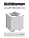
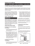
PLASMA FREEZERS and
BLOOD BANK REFRIGERATORS
Installation, Operation and
Maintenance Instructions
INSPECTION
When the equipment is received, all items should be carefully checked against the bill of lading to
insure all crates and cartons have been received. All units should be inspected for concealed
damage by uncrating the units immediately. If any damage is found, it should be reported to the
carrier at once, and a claim should be filed with the carrier. This equipment has been inspected and
tested in the manufacturing facility and has been crated in accordance with transportation rules and
guidelines. Manufacturer is not responsible for freight loss or damage.
INSTALLATION
GENERAL
Insure that the cabinet crate is on a smooth level surface. While supporting the cabinet cut the
banding straps that secure the cabinet to the crate base. Check and confirm that the casters/legs
are screwed completely and tightly into the cabinet base. Be aware that the cabinet is top heavy
and carefully remove the cabinet from the crate base.
If the condensing unit compressor is semi-hermetic, it is secured for shipping on the 1 door and 2
door models. Remove the spring clips and loosen the mounting bolts prior to operation. See
the label attached to the condensing unit. If the condensing unit compressor is hermetically sealed,
no spring clips or mounting bolts are present.
If for some reason the doors are not squared up on the cabinet, the doors can be adjusted. Opening
the door(s) and loosening the screws that hold both the top and bottom hinges to the cabinet can
accomplish this. After adjusting the door so that it is aligned correctly, tighten the screws to securely
hold the hinges in place.
1
7/09 124064
VAPORIZER INSTALLATION
The Plasma Freezers require the installation of the condensate vaporizer, which is shipped inside
the unit compartment. The vaporizer should be mounted to the cabinet bottom. See View 1. In lieu
of the vaporizer, these units can be plumbed to a floor drain following local plumbing codes.
Note: Disconnect power
prior to installation.
1.
Connect the power cord
to the vaporizer and
place it in the vaporizer
bracket.
2.
Attach the vaporizer to
the unit using the four
screws as shown. Make
sure the plastic drain
tube is in the vaporizer
pan.
View 1
LOCATION
The refrigeration system located at the top of the cabinet requires free air access for proper
operation. Allow a minimum four-inch clearance on the top, rear, and sides of the cabinet. The
cabinet should also be leveled when it is placed in its permanent location.
ELECTRICAL
Check the proposed outlet to be used to insure that the voltage, phase, and current carrying
capacity of the circuit from the electrical panel correspond to the requirements of the cabinet.
NEVER use an extension cord to wire any unit. On permanently connected units, those not
furnished with a plug-in service cord, all inter-wiring between the electrical panel and the unit must
be done in accordance with the National Electric Code and all state and local codes. See serial tag
for electrical data.
2-10VDC temperature retransmit is standard on some models, optional on others. See the
following pages for details and also see the controller programming manual for configuration details.
An optional 4-20mA temperature retransmit is also available.
2
Observe all Warning Labels. Disconnect power supply to eliminate injury from electrical
shock or moving parts when servicing equipment.
3
4
OPERATION
The plasma freezers and blood bank refrigerators employ a unit cooler evaporator located inside
the cabinet as the heat-removing source. Through the refrigeration process, heat is captured in the
evaporator, transferred to the condensing unit on top of the cabinet, and expelled to the surrounding
outside air. It is extremely important to allow a four-inch clearance on the top, rear, and sides of the
unit for the refrigeration process to function properly.
These refrigerators and freezers utilize a programmable controller to control the temperature and
defrost settings. The controller, which is located on the facade of the unit, is factory set. Please see
the separate default settings sheet and instructions on the operation of the controller used in the
Plasma Freezers. See the separate instructions on the operation of the controller used in the Blood
Bank Refrigerators.
Note: These cabinets are equipped with two switches located on the façade. One is the main power
ON/OFF switch for the unit. The other is a three-position switch for the battery-powered alarm. The
alarm switch is placed in the middle, or OFF position, for shipment. When the cabinet is put into
operation, the top of the switch should be pushed in to the ON position. With the switch in the ON
position, the battery will sound the alarm if the main power to the cabinet is interrupted. The switch
flipped to the bottom position is used to test the battery. This test must be done with power
uninterrupted to the cabinet. The alarm will sound if the battery is good. This test should be done
periodically. The battery is located inside the control box that is on top of the unit behind the façade.
CAUTION: Disconnect the power to the cabinet when going into the control box to replace
the battery.
REFRIGERATORS
During the operation of a refrigerator, frost will periodically form on the coil surface. Each time the
compressor cycles "off", the evaporator fans will continue to run, which will keep the internal
temperature uniform and at the same time remove any frost build up on the coil. The water
produced will collect in the unit cooler drain pan and travel down the drain tube to the condensate
vaporizer.
FREEZERS
After shutting the door on freezer models, a short amount of time must be allowed before the door
can be reopened. This is due to the tight seal maintained between the door and the cabinet. Waiting
a few moments for the pressure to equalize permits the door to be opened easily.
A positive defrost is required to remove frost from the coil in freezer models. This is accomplished
by energizing heaters during the defrost cycle that are positioned on the coil surface. The
programmable controller is factory set to allow four defrosts per day.
As the preset defrost time is reached, the controller automatically terminates the refrigeration
process by turning off the condensing unit and unit cooler fan motors, and energizes the defrost
heaters. As the coil temperature increases, the frost begins to melt producing water that runs down
the coil to the unit cooler drain pan and exits through the drain tube to the vaporizer. After all the
frost has been removed and the coil temperature reaches approximately 10˚C, defrost is terminated
through the action of the defrost termination control located on the unit cooler, and the refrigeration
process resumes. In order to insure that any excess water remaining on the coil is not sprayed into
the cabinet interior, and all heat generated by the defrost is removed, the unit cooler fans will not
operate until the coil temperature reaches approximately -10˚C.
5
GLYCERIN WELL ASSEMBLY
Important: For accurate product temperature
reading, the product-sensing bulb must be
immersed in glycerin solution contained in the
provided well.
One or two glycerin wells, along with a six-ounce
container, or containers, of glycerin are furnished
with each model. The purpose of the glycerin is to
simulate the product stored in the refrigerator or
freezer. The glycerin temperature reflects the
product's temperature during normal operation.
After the unit is put into operation, remove the
stopper at the top of the glycerin well. Check to
make sure that the temperature indicating or alarm
sensing bulb is positioned inside and at the bottom
of the glycerin well. Add the six ounces of glycerin
that has been provided into the glycerin well.
Reinstall the stopper to the top of the glycerin well.
MAINTENANCE
PERIODIC CLEANING
Beginning with the initial installation, the interior surfaces of the cabinet should be periodically
wiped down with a solution of warm water and baking soda. This solution will remove any odors
from spillage that has occurred. The exterior of the cabinet should also be cleaned frequently with a
commercial grade of glass cleaner. Caution: Do not use an abrasive or alkaline solution.
Monthly cleaning of the condenser will aid the heat transfer characteristics of the refrigeration
system and increase its efficiency. Dust, dirt, and lint will tend to accumulate on the fins of the
condensing unit. This obstruction will affect the flow of air through the condenser, thereby lowering
the efficiency of the system. A stiff bristled brush can be used to loosen these particles that are
attached to the fins so that they may be removed with a vacuum cleaner. Do not use a wire brush
for cleaning the condenser. Important: Failure to keep the condenser coil clean and clear of
obstructions could result in temperature loss and damage to the compressor. Do not use a
wire brush to clean the condenser.
All moving parts have been permanently lubricated and will generally require no maintenance.
6
DRAWER REMOVAL
The blood storage cabinet
comes equipped with eight
stainless steel drawers per
cabinet door opening. To
remove for cleaning, move
the drawer forward; locate
the black release tabs
found on each drawer slide
rail. See illustration. Move
the release tabs on each
side to the release position
and slide the drawer
towards you and remove.
To install a drawer, guide
the drawer inner and outer
slide rail assembles
together and push the
drawer to the back of the
cabinet until the black
release tab is latched and
locked.
DRAWER SLIDE REMOVAL/ADJUSTMENT
Each drawer slide is independently removable and can be adjusted to different levels. First
remove the drawer per above instructions. Release the locking tabs located on the drawer
slide, move the front tab up and release the tab in the back of the cabinet, by sliding the
locking tab towards the front. See illustration. Unhook the drawer slide assembly from both
the front and back shelf standards by lifting up on the assembly.
To install a drawer slide, reverse the process used to remove the slide. Secure the locking
tabs into position after the drawer slide assembly is in place. Reinstall the drawer.
7
MAINTENANCE SERVICE AND ANALYSIS GUIDE
REFRIGERATION SYSTEMS - ALL MODELS
MALFUNCTION
POSSIBLE CAUSE
SOLUTION
Compressor will not start no hum
1.
2.
3.
4.
5.
Service cord unplugged
Fuse blown or removed
Overload tripped
Control stuck open
Wiring incorrect
1.
2.
3.
4.
5.
Plug in service cord
Replace fuse
Determine reasons and correct
Repair or replace
Check wiring against the diagram
Compressor will not start hums but trips on overload
protector
1.
2.
3.
4.
Improperly wired
Low voltage to unit
Starting capacitor defective
Relay failing to close
1.
2.
3.
4.
Check wiring against the diagram
Determine reason and correct
Determine reason and replace
Determine reason, correct or replace
Compressor starts and runs,
but short cycles on overload
protector
1. Low voltage to unit
2. Overload defective
3. Excessive head pressure
4. Compressor hot-return gas hot
Compressor operates long
or continuously
1.
2.
3.
4.
1. Determine reason and correct
2. Check current, replace overload protector
3. Check ventilation or restriction in
refrigeration system
4. Check refrigerant charge, fix leak if
necessary
Short of refrigerant
Control contact stuck
Evaporator coil iced
Restriction in refrigeration
system
5. Dirty condenser
1.
2.
3.
4.
Compressor runs fine, but
short cycles
1.
2.
3.
4.
5.
1.
2.
3.
4.
5.
Starting capacitor open,
shorted or blown
1. Relay contacts stuck
2. Low voltage to unit
3. Improper relay
1. Clean contacts or replace relay
2. Determine reason and correct
3. Replace
Relay defective or burned out
1. Incorrect relay
2. Voltage too high or too low
1. Check and replace
2. Determine reason and correct
Refrigerated space too warm
1.
2.
3.
4.
5.
6.
1.
2.
3.
4.
5.
6.
Standard temperature system
freezes the product
1. Control setting is too low
2. Control points stuck
1. Reset the control
2. Replace the control
Objectionable noise
1.
2.
3.
4.
5.
1.
2.
3.
4.
5.
Overload protector
Cold control
Overcharge
Air in system
Undercharge
Control setting too high
Refrigerant overcharge
Dirty condenser
Evaporator coil iced
Not operating
Air flow to condenser or
evaporator blocked
Fan blade hitting fan shroud
Tubing rattles
Vibrating fan blade
Condenser fan motor rattles
General vibration
6. Worn fan motor bearings
Pan Area
1. No cooling
2. Too cold
Fix leak, add refrigerant
Repair or replace
Determine cause, defrost manually
Determine location and remove restriction
5. Clean condenser
Check wiring diagram
Differential too close - widen
Reduce charge
Purge and recharge
Fix leak, add refrigerant
Reset control
Purge refrigerant
Clean condenser
Determine reason and defrost
Determine reason, replace if necessary
Remove obstruction for free airflow
Reform or cut away small section of shroud
Locate and reform
Replace fan blade
Check motor bracket mounting, tighten
Compressor suspension bolts not loosened
on applicable models - loosen them
6. Replace fan motor
1. Make sure switch is in the "on" position
2. Adjust temperature control - see instructions
under pan area
3. Adjust temperature control - see instructions
under pan area
3. Too warm
8