Download "user manual"
Transcript
operation instructions member and USers manual www.teleflexmarine.com i s o 9 0 0 1 Electronic Power Steering for Outboard Powered Vessels MANUFACTURED BY MARINE CANADA ACQUISITION LIMITED PARTNERSHIP DBA TELEFLEX CANADA To the End User (Owner) Thank you for choosing an Optimustm Steering System by Teleflex Marine. This User’s manual contains all of the information that you will require for safe use of your steering system and must remain on the boat. All information, illustrations and specifications in this manual are based on the latest information available at the time of publishing. The illustrations used in this manual are intended as representative reference views only. Moreover, because of our continuous product improvement policy, we may modify information, illustrations and/ or specifications to explain and/or exemplify a product, service or maintenance improvement. We reserve the right to make any change at any time without notice. For the latest information, go to www.teleflexmarine.com All Rights Reserved: No part of this publication may be reproduced or used in any form by any means without the written permission of Teleflex Marine Incorporated. ©2012 Teleflex Marine. is a registered trademark of the American Boat & Yacht Council (http://www.abycinc.org) NMEA 2000® is a registered trademark of the National Marine Electronics Association. Optimus is a trademark of Teleflex Marine. i © 2012 Teleflex Marine, Inc. Optimus Operations Manual, Rev. A Notice to the Operator Throughout this publication, Dangers, Warnings and Cautions (accompanied by the International Hazard Symbol ) are used to alert the user to special instructions concerning a particular service or operation that may be hazardous if ignored, performed incorrectly, or carelessly. Observe Them Carefully! These “safety alerts” alone, cannot eliminate the hazards that they signal. Strict compliance to these special instructions when operating and maintaining, plus “common sense” operation, are major accident prevention measures. Immediate hazards which, if not acted upon, WILL result in severe personal injury or death. warning caution Hazards or unsafe practices which, if not acted upon, COULD result in severe personal injury or death. Hazards or unsafe practices which COULD result in minor injury or product or property damage. Information which is important to proper use or maintenance, but is not hazard-related. © 2012 Teleflex Marine, Inc. Optimus Operations Manual, Rev. A ii INDEX 1.0 Safety Instructions................................................................ 1 Safety Labels....................................................................... 3 Abbreviations....................................................................... 5 2.0 Introduction 2.1Welcome...................................................................... 6 2.2 Optimus System Overview.............................................. 6 2.3 Optimus EPS System Diagram........................................ 7 3.0 First Time Operation.............................................................. 8 3.1 Locate the Following Steering System Components.......... 8 3.2 Initial Start Up............................................................ 12 3.3 System Inspection....................................................... 13 3.4 Installation Checks...................................................... 15 3.5 Initial Sea Trial............................................................ 18 4.0 System Use......................................................................... 19 4.1 Before Each Use......................................................... 19 4.2 Multiple Stations......................................................... 20 4.3 Autopilot Operation ..................................................... 18 5.0 CANtrak Display ................................................................. 21 5.1 Purpose..................................................................... 21 5.2 CANtrak Display Navigation.......................................... 22 5.3 CANtrak Display Map – All Helms Active........................ 23 5.4 All Helms Active Screens............................................. 24 6.0 System Faults & Hazards..................................................... 28 6.1 Hazard Definitions....................................................... 28 6.2 System Fault Handling................................................. 29 6.3 Buzzer........................................................................ 36 6.4 Reduced Performance................................................. 36 6.6 Steering Fluid............................................................. 36 7.0 Maintenance....................................................................... 37 8.0 Troubleshooting................................................................... 39 9.0 Replacement Parts.............................................................. 40 9.1 SeaStar Electronic Power Steering Fluid........................ 40 10. Warranty............................................................................. 41 10.1 Statement of Limited Warranty................................... 41 10.2 Return Goods Procedure ........................................... 41 APPENDIX A - Specifications...................................................... 42 iii © 2012 Teleflex Marine, Inc. Optimus Operations Manual, Rev. A 1.0Safety information warning The safety information provided below is intended to inform you of the dangers that may be present before, during and after use. It is critical that you read and understand ALL the points noted. The safe operation of the steering system is dependant upon proper installation and maintenance, common sense, safe judgement and the knowledge/expertise of the operator. Every installer/user of the steering system should know the following requirements ‘before’ installing/using the steering system. If you have any questions regarding any of these warnings, contact Teleflex Marine. To reduce risk of severe injury or death: warning The Optimus EPS System MUST be installed by ONLY an authorized Teleflex Marine dealer. 1.Always wear a Coast Guard Approved personal flotation device (PFD) and use an engine shut-off cord (lanyard). 2.Read and understand this User’s manuals and the Quick Reference Card provided with your steering components. 3.Optimus components are highly engineered and safety tested to ensure system integrity. DO NOT substitute any component with non-Optimus components, as this may compromise system performance/reliability. Prior to every use Perform a system inspection as outlined below. Refer to Section 3.3 for further details. 1.Check steering fluid level in all steering pumps. 2.Verify immediate steering response when turning steering wheel(s). 3.Inspect all steering hoses, fittings and mechanical and electrical cables for wear, kinks, or leaks. 4.Check for binding, loose, worn or leaking steering or shift/throttle control components. 5.Verify proper shift and throttle response for all control handles. 6.Verify that no alarms or warnings are shown on the CANtrak display. do not operate boat if any component is not in proper working condition. © 2012 Teleflex Marine, Inc. Optimus Operations Manual, Rev. A 1 Safety Information Continued During use 1.wear a coast guard-approved personal flotation device (PFD). 2.Attach engine shut-off cord (lanyard) to your pfd. 3.Never allow anyone not familiar with the operation of the steering system to operate the boat at ANY time. 4.Know and adhere to the operator restrictions for you area including: • Federal Laws/Regulations, • State Laws/Regulations and • Municipal Laws/Regulations. do not operate boat if any component is not in proper working condition. After use Rinse off SmartCylinders thoroughly using “fresh, clean water” only. Do NOT rinse PCM or pumps. • Cleaning fluids containing ammonia, acids or any other corrosive ingredients must not be used for cleaning any par of the Optimus Steering Controls. Maintenance Maintain Optimus Steering System as directed in Section 7 of this Manual. Keep our waters clean for all current and future users. Dispose of ALL fluids in accordance with your local regulations. 2 © 2012 Teleflex Marine, Inc. Optimus Operations Manual, Rev. A Safety Labels warning NOTE: The labels below should call attention to the possible hazards associated with the equipment shown later in this manual (see Section 3.1) Hydraulic Pump Label CAUTION HOT Pump Control Module (PCM) Label © 2012 Teleflex Marine, Inc. Optimus Operations Manual, Rev. A 3 Safety Labels Continued SmartCylinder Label Steering Service Valve Label (May be installed if the valve is hidden from view.) 4 © 2012 Teleflex Marine, Inc. Optimus Operations Manual, Rev. A Abbreviations The following abbreviations are used in this manual: ABYC American Boat & Yacht Council APAutopilot CAN Control Area Network EPS Electronic Power Steering GPS Global Positioning System INFOInformation HIHigh LOLow MPH Miles Per Hour NMEA National Maritime Electronics Association NMEA 2000® The special protocol for digital communication on a CAN Bus RPM Revolutions Per Minute STBD Starboard (right) Note: Some abbreviations not listed here may be found in their respective sections. © 2012 Teleflex Marine, Inc. Optimus Operations Manual, Rev. A 5 2.0Introduction 2.1 Welcome notice Welcome to the world of electronic power steering. Please take a few minutes to go thru the System Overview and the First Time Operation sections to assure your safety and to get the most enjoyment from the Optimus EPS steering system. 2.2 Optimus EPS System Overview A typical Optimus EPS system consists of an Electronic Helm located behind the steering wheel which is electrically connected to a Pump Control Module. This module converts the steering wheel action to electrical signals which operate Hydraulic Pumps. These pumps move the smart steering cylinders (SmartCylinders) at each engine. A position sensor is part of the SmartCylinders and provides engine position information back to the Pump Control Module. Service Valves are installed between the Hydraulic Pumps and the SmartCylinders to allow for manual positioning of the engines should a fault occur or for use by the technician during servicing. A CANtrak Display shows system operation and fault warnings. The CANtrak Display also permits system sensitivity and configuration adjustments. The Optimus EPS system includes many advancements to make the system as failsafe as possible. These include redundant sensors, fault-tolerant communications, self-monitoring and fault communications to notify and advise the operator in case of fault. 6 © 2012 Teleflex Marine, Inc. Optimus Operations Manual, Rev. A 2.3 Optimus EPS System Diagram © 2012 Teleflex Marine, Inc. Optimus Operations Manual, Rev. A 7 3.0 first time operation 3.1 Locate the Following Steering System Components 3.1.1 Electronic Helm(s) The steering wheel is attached to this unit and it may be located immediately under the wheel or just behind the dash panel. The images below show typical helms. EPS Front Mount Helm EPS Rear Mount Helm EPS Classic Tilt Helm EPS Sport Plus Tilt Helm 3.1.2 Circuit Breakers for Optimus EPS System These are supplied by the installer and may be mounted in a variety of locations. Check near the batteries, in the circuit breaker box, or near the Pump Control Modules or Hydraulic Pumps. There should be a 60 amp breaker for each PCM power feed. 8 © 2012 Teleflex Marine, Inc. Optimus Operations Manual, Rev. A 3.1.3 Pump Control Module (PCM) This is located in a dry area and can usually be found inside the center console, in the area behind the dash, or in a compartment near the engines or batteries. The PCM is always located close to the Hydraulic Pumps. There will be one PCM on twin engine boats. 3.1.4 Hydraulic Pumps Hydraulic Pumps are located near the PCM. They can usually be found in a compartment near the engines, the center console or behind the dash. There is one pump for each engine. Note: these pumps look a lot like the trim pumps that tilt the engines but can be distinguished by the decal and the green/blue SeaStar Electronic Power Steering Fluid. The pumps have the steering fluid reservoir and this is where the fluid level is checked and steering fluid is added. © 2012 Teleflex Marine, Inc. Optimus Operations Manual, Rev. A 9 3.1.5 SmartCylinders On outboard boats these are always located just below the engine cowling and are attached to the engine tiller arm. There will be one SmartCylinder for each engine. 3.1.6 Steering Service Valves These are located in the hydraulic lines that go from the Hydraulic Pumps to the SmartCylinders. There is one for each engine. These are used for servicing and emergency operation. The steering service valves permit the bypass of the EPS system and allow the engines to be manually positioned. They should only be used in the event of an EPS system failure. Instructions on how to proceed will be supplied on the CANtrak display or in Section 6.2.5. warning 10 Wear a coast guard-approved personal flotation device (PFD) when manually realigning engines. © 2012 Teleflex Marine, Inc. Optimus Operations Manual, Rev. A 
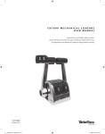
3.1.7 Cantrak Display There is a display at each helm station that shows the system status and allows system adjustments. © 2012 Teleflex Marine, Inc. Optimus Operations Manual, Rev. A 11 3.2 Initial Start Up Turning on the ignition switch will turn on the Optimus EPS system. The CANtrak Display will turn on and the steering will become active at all helms. After reading the initial warning screen press the INFO button and follow the prompts for a system inspection. Splash Screen 3 Sec interval info Initial Warning OK NEXT System Check 1 NEXT System Check 2 back System Check 3 back OK All Helms Active warning 12 On multiple helm station boats all helms are active when the Optimus EPS is turned on. This is the same you would find on a conventional hydraulic steering system. © 2012 Teleflex Marine, Inc. Optimus Operations Manual, Rev. A 3.3 System Inspection Failure to adhere to these warnings may result in loss of boat control, leading to possible ejection from vessel; causing property damage, personal injury and/or death. 1.Check steering fluid level in all steering pumps. Each Optimus hydraulic pump has a steering fluid reservoir. Ensure the fluid level is between the MIN and MAX marks on the reservoir as shown in the figure below. Use only SeaStar Electronic Power Steering Fluid in the Optimus EPS System. 2.Verify immediate steering response when turning steering wheel(s). Turn the steering wheel slowly to port and to starboard and make sure the engines follow the commands. Watch that the hoses and cables move freely without any snags or hang-ups. 3.Inspect all steering hoses, fittings and mechanical and electrical cables for wear, kinks, or leaks. Check all steering hoses and fittings between the pump, service valves and cylinders for any signs of leakage, kinking, wear or chafing. Check all electrical and mechanical cabling for abrasion, wear, rubbing or chafing. Check that all connections are tight and free of corrosion. © 2012 Teleflex Marine, Inc. Optimus Operations Manual, Rev. A 13 System Inspection Continued 4.Check for binding, loose, worn or leaking steering or shift/ throttle control components. Check all shift and throttle cables for signs of wear, damage or chafing. Check that all linkages and cables move freely and are not binding or corroded. 5.Verify proper shift and throttle response for all control handles. Check that all shift and throttle levers operate freely and cause the engines to shift accordingly. Put the engines in neutral idle mode and confirm that the throttle responds correctly and returns to idle. 6.Verify that no alarms or warnings are shown on the CANtrak display. If any warnings are found, follow the instructions on the CANtrak screen or refer to Section 6 of this manual before proceeding Read the System Inspection steps on the CANtrak display and acknowledge them by pressing the right hand most button under OK. warning DO NOT OPERATE BOAT IF ANY COMPONENT IS NOT IN PROPER WORKING CONDITION. After becoming familiar with the system inspection process, the operator can use the OK button to acknowledge that the system inspection process was understood and completed and can then go directly to the steering mode screen. warning 14 It is recommended the full system inspection be reviewed on a regular basis to retain familiarity. © 2012 Teleflex Marine, Inc. Optimus Operations Manual, Rev. A 3.4 Installation Checks To verify correct installation of the Optimus SmartCylinder, perform the following installation checks when the boat is delivered and after each boat servicing. warning Failure to perform these checks may result in damage to the SmartCylinder sensor and affect the safe operation of the boat’s steering. 1. Interference Checks - Confirm that there is no interference between the steering cylinder(s), splashwell or outboard engine or any combination of these parts by performing the steps below. At the same time for each step also check that the hoses and cables are moving freely with no rubbing or binding (see figures below and on right page). a)With the engines fully tilted DOWN, turn the steering wheel from hard over to hard over and confirm that no interference occurs. b) With the engines fully tilted UP, turn the steering wheel from hard over to hard over and confirm that no interference occurs. c) Trim the port engine fully down and the starboard engine fully up. Turn the steering wheel from hard over to hard over and confirm that no interference occurs. d) Trim the starboard engine fully down and the port engine fully up. Turn the steering wheel from hard over to hard over and confirm that no interference occurs. caution © 2012 Teleflex Marine, Inc. If any issues are found during the installation checks, immediately return the boat to the service dealer for those issues to be remedied. Optimus Operations Manual, Rev. A 15 Installation Checks continued Make sure that all cables and hoses move freely and that the cylinders and engines are clear at steering extremes. Engine side view, when tilted 16 © 2012 Teleflex Marine, Inc. Optimus Operations Manual, Rev. A Installation Checks continued 2.Sensor cable - Confirm that the SmartCylinder Sensor Cable is tied securely to the hoses with gradual bends as shown in the following diagrams. ties secured to FittingS SMOOTH BEND NO KINKING Ties no more than 6” apart © 2012 Teleflex Marine, Inc. Optimus Operations Manual, Rev. A 17 3.5 Initial Sea Trial warning With the engine lanyard properly connected to you and the passengers secure carefully proceed to a section of deep open water at a slow to moderate speed. Use the trip to get a feel for the steering response. When in open water that is deep enough to assure you will not run aground try various maneuvers with the boat at various speeds until you are comfortable operating the boat. Be sure to spend some time backing up at a slow speed. Once familiar with the operation run the boat in a safe normal fashion and enjoy the steering. If settings require adjustment during the sea trial, refer to Section 5.0 for further details. 18 © 2012 Teleflex Marine, Inc. Optimus Operations Manual, Rev. A 4.0 system use If this is the first-time use OR for more details, see Section 3 of this manual. 4.1 Before Each Use warning Prior to every use: Perform a system inspection as outlined below, see Section 3.3 for further details. 1.Check steering fluid level in all steering pumps. 2.Verify immediate steering response when turning steering wheel(s). 3.Inspect all steering hoses, fittings and mechanical and electrical cables for wear, kinks, or leaks. 4.Check for binding, loose, worn or leaking steering or shift/throttle control components. 5.Verify proper shift and throttle response for all control handles. 6.Verify that no alarms or warnings are shown on the CANtrak display. warning Do NOT operate boat if any component is not in proper working condition. 4.2 Multiple Station Boats caution © 2012 Teleflex Marine, Inc. On multiple helm station boats all helms are active when the Optimus EPS is turned on. This is the same you would find on a conventional hydraulic steering system. Optimus Operations Manual, Rev. A 19 4.3 Autopilot Operation warning Always read and understand the autopilot operation instruction completely before engaging the autopilot mode. The Optimus EPS steering system is designed to interface with many autopilot controllers. See your Autopilot’s documentation for specific model compatibility. On boats with an autopilot the steering effort may be noticeably higher when the autopilot is engaged. This resistance is user adjustable, see Section 5.4.3 of this manual. When any wheel is turned with the autopilot engaged, the helm will take control of the system and manually override the autopilot. When this happens, the steering resistance will return to normal until the autopilot re-engages. See your autopilot user’s manuals for specific system behavior. warning Never leave the helm station unattended when the autopilot is engaged. The Title Bar will display “Autopilot Mode” when the autopilot is engaged. 20 © 2012 Teleflex Marine, Inc. Optimus Operations Manual, Rev. A 5.0CANtrak Display 5.1 Purpose The Optimus CANtrak display has an easy to navigate menu system, adjustable backlighting for night use and includes a cover to protect it from the sun when not in use. The CANtrak display serves these purposes: 1.Displays the current system operating conditions. 2.Handles system faults by: a) Displays system warnings in case of a system fault. b) Sounds an audible alarm in case of a system fault. c) Instructs the operator what to do in case of a system fault. 3.Permits changes to the basic system settings. 4.Provides system and diagnostic information For details on CANtrak operation see sections 5.2 through 5.4 of this manual. © 2012 Teleflex Marine, Inc. Optimus Operations Manual, Rev. A 21 5.2 CANtrak Display Navigation The five buttons at the bottom of the unit are used to select various actions. The five boxes at the bottom of the display screen will indicate the legend for each button. These legends vary based on what is on the screen. Word or SymbolIdentifies a function or setting Moves the cursor arrow up the screen to the next item Moves the cursor arrow down the screen to the next item First press selects the parameter to change and subsequent press index the selection Takes you back one step Reduces the setting of a selected item Increases the setting of a selected item OK Accepts a given statement or condition and advances to the next screen Moves the unit back one level. CANtrak display lighting CANtrak display contrast 22 © 2012 Teleflex Marine, Inc. Optimus Operations Manual, Rev. A 5.3 CANTrak Display Map – All Helms Active (Normal Steering Mode) The following diagram shows the progression from the Splash Screen to the All Helms Active Screen, then illustrates the various choices available from the All Helms Active screen. Splash Screen 3 Sec interval info Initial Warning NEXT System Check 1 NEXT System Check 2 back OK System Check 3 back OK All Helms Active Diagnostics Network nodes Node Information Adjust LO Speed Helm Turns HI Speed Helm Turns LO Speed Helm Effort HI Speed Helm Effort AP Helm Effort Display Contrast Brightness © 2012 Teleflex Marine, Inc. Optimus Operations Manual, Rev. A 23 5.4 All Helms Active Screens 5.4.1All Helms Active (Normal Steering Mode) The All Helms Active Mode screen will be displayed under normal operating conditions after the startup warning has been acknowledged. The All Helms Active screen displays the current system operating conditions. It shows the engine RPM as well as the rudder angle. It also allows access to the Diagnostics, Adjustment and Display menu screens. 5.4.2 Diagnostics (DIAG) Screen The Diagnostics screen allows the user the access to basic system diagnostics tools including network node information and a CAN message viewer. Diagnostics Screen 24 © 2012 Teleflex Marine, Inc. Optimus Operations Manual, Rev. A 5.4.3Adjust (ADJ) Screen The Adjust screen allows adjustment of system parameters which affect steering operation and feel. Specific details of each parameter are listed below. Changes made in the Adjust screen are saved to memory upon exiting the Adjust screen. You will be prompted to save changes before exiting as shown in the display. Pointer buttons Scroll Bar Low Speed Turns This setting changes the number of turns when the vessel is running at low speeds. The adjustable range is 3.5 to 8 Turns. High Speed Turns This setting changes the number of turns when the vessel is running at high speeds. The adjustable range is 3.5 to 8 Turns. Low Speed Steering Effort This setting changes the steering resistance when the vessel is running at low speeds. It is adjustable between 1 and 100. High Speed Steering Effort This setting changes the steering resistance when the vessel is running at high speeds. It is adjustable between 1 and 100. Autopilot Engaged Steering Effort This setting increases the steering resistance slightly when autopilot is engaged to prevent accidental course corrections with the wheel. It is adjustable between 0 and 100. © 2012 Teleflex Marine, Inc. Optimus Operations Manual, Rev. A 25 5.4.3Adjust (ADJ) Screen continued notice The steering resistance and turns have both low speed and high speed settings. The low speed and high speed set points may be determined by various sources, for example: Engine RPM, Throttle Postiion, etc. These are configured by your dealer and are not adjustable. The number of turns and steering resistance at these low and high speeds are user adjustable. These settings will automatically increase smoothly between the low speed and high speed points as shown below. caution 26 Adjusting steering effort for steering turns can significantly impact boat handling. Proceed with caution after making any changes. © 2012 Teleflex Marine, Inc. Optimus Operations Manual, Rev. A 5.4.4 Display (DISP) Screen The Display screen allows adjustment of the brightness and contrast of the CANtrak display. These should be adjusted to provide good daytime and night time visibility of the display. © 2012 Teleflex Marine, Inc. Optimus Operations Manual, Rev. A 27 6.0 system faults & hazards Should a steering fault occur, it will be communicated to the user though the CANtrak display. This section defines the two types of hazards you may experience and how the system will handle each. 6.1 Hazard Definitions 6.1.1 Danger A danger fault is a critical system fault which will result in limited steering performance and requires immediate action and immediate return to the nearest port. Depending on the type of fault, steering will either be restricted to one engine, or suspended and the engines may need to be manually realigned and the vessel driven using the throttles. In the case of a danger fault, the CANtrak buzzer will sound continuously (until muted) and the CANtrak display will advise the operator on how to proceed. See Section 6.2.1 for danger fault handling specifics. 6.1.2 Warning A warning is a non-critical system fault which will either maintain full steering system operation or cause the steering speed to be reduced. Although a warning does not always adversely affect steering performance it is an indication of a problem in the system and should be remedied. In the case of a warning fault, the CANtrak buzzer will sound intermittently (until muted) and the CANtrak will display the Warning screen. See Section 6.2.3 for warning fault handling specifics. 28 © 2012 Teleflex Marine, Inc. Optimus Operations Manual, Rev. A 6.2 System Fault Handling In case of a Danger or Warning message, the CANtrak display will advise the operator how to proceed. The following sections describe what to expect in case of either fault. 6.2.1 Danger Fault Handling A danger fault is a critical system fault which will result in limited steering performance and requires immediate action and return to the nearest port (see 6.1.1). During a danger fault, the CANtrak display will display DANGER across the top, sound a continuous buzzer (until muted) and display fault information and handling in three zones. See the figure below. Active Fault Description Zone System Status Zone Fault Handling Instructions Zone Will appear if multiple faults are active to allow user to scroll through Active Fault Description Zone Provides details specific to the system fault. These will include a brief description of the fault and are primarily for troubleshooting purposes. System Status Zone Displays information about the status of the system and if the system has automatically reacted to the fault. Fault Handling Instructions Zone Provides detailed instructions on how to proceed. In the case of a danger fault, this will instruct the operator what to do and how to proceed should Limp Home mode be required. © 2012 Teleflex Marine, Inc. Optimus Operations Manual, Rev. A 29 6.2.2 Limp Home When a Danger fault results in steering performance being restricted or suspended, the CANtrak may provide instructions on how to enter Limp Home mode. Limp home will provide instructions for the user to manually move the engine(s) and allow the user to “limp home” at a reduced performance. There are two Limp Home modes depending on the nature of the fault. Limp Home Mode 1 This mode occurs when the system can no longer provide steering to ANY of the engines. The CANtrak will instruct the operator to manually realign the engines using the service valves, and proceed home immediately using the shift and throttle controls to control the vessel as shown in the figure below. 30 © 2012 Teleflex Marine, Inc. Optimus Operations Manual, Rev. A 6.2.2 Limp Home continued Limp Home mode 2 This mode occurs when the system can no longer provide steering to ONE of the engines. The CANtrak will instruct the operator to realign the non-responsive engine, tilt it out of the water and proceed home immediately using the responsive engine as shown in the figure below. © 2012 Teleflex Marine, Inc. Optimus Operations Manual, Rev. A 31 6.2.3 Warning Fault Handling A warning is a non-critical system fault which will either maintain full steering system operation or cause the steering speed to be reduced. During a warning fault, the CANtrak will display the same information as with a danger fault but WARNING will appear across the top of the screen and the buzzer will sound intermittently (until muted). See the figure. Active Fault Description Zone System Status Zone Fault Handling Instructions Zone Will appear if multiple faults are active to allow user to scroll through User may exit the Warning screen and return to run screen The user may choose to exit the Warning screen and return to the All Helms Active screen by pressing the exit button, in which case the system will flash a warning icon on the run screen as shown on the next page. This icon will remain in place until the fault is repaired. If the system recovers from the fault, for example if a battery runs low and is subsequently charged, the warning screen will disappear and the system will automatically resume normal operation. 32 © 2012 Teleflex Marine, Inc. Optimus Operations Manual, Rev. A 6.2.3 Warning Fault Handling continued Although the system may still operate normally under many warning faults, the vessel should still be returned to port and serviced immediately. run screen with system warning Some system faults may result in a reduced steering response warning. This means that the system will continue to steer normally but may respond slower. © 2012 Teleflex Marine, Inc. Optimus Operations Manual, Rev. A 33 6.2.4 System Fault Handling – Example The following is an example of how the system would respond to the warning fault hazard of a low port engine battery. The CANtrak display will enter the warning screen mode and pulse the system warning buzzer. The three warning screen zones will appear as shown below. This area shows the active faults Active Fault Description Zone Describes what system has done to react to fault System Status Zone Tells the User how to proceed Fault Handling Instructions Zone In this case, the CANtrak tells the user to power off any non essential devices and to seek technical support as fault handling instructions. It also informs the user that the system has switched to the starboard battery and reduced the steering speed. The vessel should be returned to port immediately for repair. 34 © 2012 Teleflex Marine, Inc. Optimus Operations Manual, Rev. A 6.2.5 CANtrak Loss of Display In the event of a loss of CANtrak display operation proceed as follows: 1.On a multiple helm station vessel each station should be equipped with a CANtrak display. Proceed to navigate from another helm station and immediately return to port for service. 2.If there are no secondary displays on board, at low speed carefully verify that the steering system operates normally then immediately and cautiously proceed to port for service. 3.In the event of a loss of steering response and CANtrak display, proceed as follows: Limp Home Mode 1 If the steering system can no longer provide steering to ANY of the engines, proceed by using Limp Home Mode 1, as follows: 1. Always wear PFD devices. 2.Put engine(s) in Neutral. 3.Open Steering Service Valves. 4.Manually center all engines. 5.Close Steering Service Valves 6.Return to port using throttles to steer. Limp Home mode 2 If the steering system can no longer provide steering to ONE of the engines, proceed by using Limp Home Mode 2, as follows: 1. Always wear PFD devices. 2.Put engine(s) in Neutral. 3.Open Steering Service Valves. 4.Turn affected engine fully away from other. 5.Close Steering Service Valves 6.Fully tilt affected engine. 7.Return to port. © 2012 Teleflex Marine, Inc. Optimus Operations Manual, Rev. A 35 6.3 Buzzer The buzzer is used to indicate a system fault. There are two different signals” 1.Continuously on. This indicates a danger fault. A danger fault is a critical system fault which will result in limited steering performance and requires immediate action and immediate return to the nearest port. See Section 6.1.1. 2. Alternating on and off. This indicates a warning fault. A warning is a non-critical system fault which will either maintain full steering system operation or cause the steering speed to be reduced. See Section 6.1.2. All signals require immediate attention. When the buzzer sounds, a screen will appear on the CANtrak indicating the cause for the alarm. The screen will also display a “mute” button which may be used to silence the alarm. 6.4 Reduced Performance Under certain fault conditions the steering response will slow down. A typical cause might be a very low battery. When this happens the CANtrak will advise the operator of the condition, indicate the reason, and supply instructions. warning Proceed with caution until the fault is corrected and normal steering operation returns. 6.5 Steering Fluid The Optimus Steering System requires genuine SeaStar Electronic Power Steering Fluid. In an emergency condition if SeaStar Electronic Power steering fluid is not available, the follow fluids may be used for a short period of time. warning • Sea Star Steering Fluid • Automatic Transmission Fluid • Motor Oil If any of the above are used in the system, then the system should be flushed and refilled with SeaStar Electronic Power steering fluid when the boat is returned to port. Never use brake fluid. 36 © 2012 Teleflex Marine, Inc. Optimus Operations Manual, Rev. A 7 .0Maintenance warning 1. Owner(s) (End Users) Following the routine maintenance schedules as outlined below, in the time frame noted will ensure years of service from your Optimus Electronic Steering System, as well as keep you and your passengers safe from the dangers that are present on and off the water. Prior to every use (see Section 3.3 for further details): 1. Check steering fluid level in all steering pumps. 2. Verify immediate steering response when turning steering wheel(s). 3. Inspect all steering hoses, fittings and mechanical and electrical cables for wear, kinks, or leaks. 4. Check for binding, loose, worn or leaking steering or shift/throttle control components. 5. Verify proper shift and throttle response to all control handles. 6. Verify that no alarms or warnings are shown on the CANtrak display. warning Do not operate boat if any component is not in proper working condition. After every use: 1. Rinse the SmartCylinders with clean water and replace Cantrak sun cover. Do NOT rinse the PCM or the pumps. 2. Qualified Marine Mechanic After the first 20 hours, then every 100 hours or 6 months thereafter (whichever comes first). 1.All points noted above. 2.Check tightness of ALL fasteners/fittings throughout the steering system. Tighten to correct torque specifications as required. 3.Check for mechanical play or slop throughout steering system, correct as required. 4.Check for signs of corrosion. If corrosion is present contact your dealer or Teleflex Marine. 5.Check all electrical cables for chaffing and wear. © 2012 Teleflex Marine, Inc. Optimus Operations Manual, Rev. A 37 Maintenance Continued After the first 200 hours or 12 months thereafter (whichever comes first). 1.All points noted above. 2.Remove support rod from engine steering/tilt tube. Clean engine steering/tilt tube and re-grease using a good quality marine grease. 3.Grease support rod liberally. 4.Grease all contact points shown in the figure below. DO NOT remover the tiller bolt to re-grease. 5.Remove the steering wheel and re-grease the wheel shaft using a good quality marine grease. 6.Inspect hydraulic oil for cleanliness; flush if required. 7.Check that the service valve is free to move and in the closed position. warning Any work being performed with the steering system MUST be completed by a qualified mechanic with the working knowledge of the system. GREASE SUPPORT ROD, TILT TUBE & SUPPORT BRACKET HOLE GREASE SUPPORT ROD, TILT TUBE & SUPPORT BRACKET HOLE 38 © 2012 Teleflex Marine, Inc. Optimus Operations Manual, Rev. A 8 .0 troubleshooting guide Optimus EPS steering will provide years of safe reliable performance with a minimum of service if properly installed. warning Whenever, in the following text, a solution calls for removal from vessel and/or dismantling of steering system components, such work must ONLY be carried out by a qualified marine hydraulic mechanic. Teleflex offers the following as a guide only and is not responsible for any consequences resulting from incorrect dismantling repairs. Optimus steering systems have been designed with protection against over-pressure situations, with the inclusion of a pressure relief valve and circuit breakers, to minimize the possibility of total loss of steering. Most faults occur when the installation instructions are not followed and usually show up immediately upon filling the system. provided below, are the most common faults encountered and their likely cause and solution. FAULT cause solution 1.CANtrak does not turn on? Batteries not turned ON, or in poor working condition. Load test batteries. Ignition wires disconnected. Confirm all connections are in place. CANtrak connection damaged and/ or not connected. Inspect wires for damage. 2.High/Low Speed wheel turn setting not working Tachometer is not relaying information. Confirm Tachometer is operating properly (check connections). CANtrak NOT writing proper information. Confirm that your settings have been saved. If they are not saved, contact Tech support. 3.One engine does not steer, but CANtrak display is on. Check circuit breaker for the engine. Reset breaker. If it immediately trips a second time look for a shorted or pinched wire or failed component. © 2012 Teleflex Marine, Inc. Optimus Operations Manual, Rev. A 39 9 .0 replacement parts 9.1 SeaStar Electronic Power Steering Fluid Quart HA5482 Gallon HA5483 For full listing of part numbers, please refer to the Optimus 50 Installation Manual, part no. 682100. 40 © 2012 Teleflex Marine, Inc. Optimus Operations Manual, Rev. A 1 0.0 warranty 10.1 Statement of Limited Warranty notice We warrant to the original retain purchaser that Marine Canada Acquisition Limited Partnership DBA Teleflex Canada (herein forward referred to as Teleflex Canada) products have been manufactured free from defects in materials and workmanship. This warranty is effective for two years from date of purchase, excepting that where Teleflex Canada products are used commercially or in any rental or income producing activity, then this warranty is limited to one year from the date of purchase. We will provide replacement product without charge, for and Teleflex Canada product meeting this warranty, which is returned (freight prepaid) within the warranty period to the dealer from whom such product were purchased, or to us at the appropriate address. In such a case, Teleflex Canada products found to be defective and covered by this warranty will be replace at Teleflex Canada’s option, and returned to the customer. The above quoted statement is an extract from the complete Teleflex Canada products warranty statement. A complete warranty policy is available in our Teleflex Canada products catalogue. 10.2 Return Goods Procedure Prior to returning product to Teleflex Canada under warranty, please obtain a Return Goods Authorization number (claim number). Be sure to label the goods with: a) the name and address of the sender, and b) the return good authorization number (claim number). Please address the returned goods as follows: © 2012 Teleflex Marine, Inc. From U.S.A. From Canada RGA # ? Teleflex Canada c/o UPS-Supply Chain Solutions, Inc. Door A37 1201 C Street NW Auburn, WA 98001 RGA # ? Teleflex Canada 3831 No. 6 Road Richmond, B.C. Canada V6V 1P6 Optimus Operations Manual, Rev. A 41 Aappendix Specifications OPTIMUS SYSTEM SPECIFICATIONS (Based on EPSK1200 Twin Engine Corepack) Operating Voltage: 12Vdc Maximum System Pressure: 1200 PSI # of wheel turns: Variable from 3.5 to 8 Typical Average Current Draw: ~6 to 8 Amps Oil Type: SeaStar Electronic Power Steering Fluid 42 © 2012 Teleflex Marine, Inc. Optimus Operations Manual, Rev. A © 2012 Teleflex Marine, Inc. Optimus Operations Manual, Rev. A 43 teleflex canada 3831 no. 6 road richmond, b.c. canada v6v 1p6 Phone: 604-248-3858 Fax: 604-279-2202 Web: www.teleflexmarine.com iso 10592 © 2012 marine canada acquisition limited partnership DBA teleflex canada Printed in canada Part no. 682101, Revision A