1
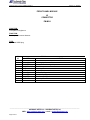
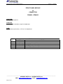
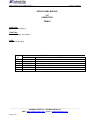
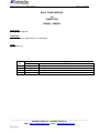
DFMA02 - FM-MC4
HARDWARE USER’S MANUAL
FM-MC4
FM FIELDSTRENGTH MEASUREMENT RECEIVER
DFMA02
DYNAMIC FM MODULATER ANALYSER
Document reference
Edition N° 1.2 – 05/2005
File reference. :
Fmmc4_nm1_2-A
___________________________________________________________________________________________________________
AUDEMAT-AZTEC SA – AUDEMAT-AZTEC INC
WEB : www.audemat-aztec.com - e-mail : [email protected]
Page 1 of 57
THE INNOVATIVE QUALITY SOLUTION FOR BROADCAST PROFESSIONALS
CERTIFICATE OF CONFORMITY
Established following the EMC 89/336/EEC and 73/23/EEC Directive
98/11/18
We, hereby, certify that the AUDEMAT-AZTEC FM_MC4 – DFMA02, equipment complies
with the dispositions of the European Community Directive concerning the rapprochement
of the legislation of the State Members related to electromagnetic compatibility (EMC
89/336/EEC Directive) and to low voltage (73/23/EEC Directive).
This declaration of conformity results from respecting EMC and low voltage requirements
and from an analysis carried out by AUDEMAT-AZTEC’s Quality Department, complying
with European standards EN 50081-1, EN 50082-1 and EN 60215.
C.E.O.
Daniel WERBROUCK
_______________________
ISO 9001 CERTIFIED _________________________________
___________________________________________________________________________________________________________
AUDEMAT-AZTEC SA – AUDEMAT-AZTEC INC
WEB : www.audemat-aztec.com - e-mail : [email protected]
Page 2 of 57
Hardware User’s manual DFMA02 FM-MC4
Edition 1.2– 05/2005
RADIO AND TELEVISION INTERFERENCE
This equipment has been tested and found to comply with the limits for a Class B
digital device, pursuant to Part 15 of the FCC rules. These limits are designed to provide
reasonable protection against harmful interference in a residential installation. This
equipment generates, uses and can radiate radio frequency energy and, if not installed
and used in accordance with the instructions, may cause harmful interference to radio
communications. However, there is no guarantee that interference will not occur in a
particular installation. If this equipment does cause harmful interference to radio or
television reception, which can be determined by turning the equipment off and on, the
user is encouraged to try to correct the interference by one or more of the following
measures :
- Reorient or relocate the receiving antenna.
- Increase the separation between the equipment and the receiver.
- Connect the equipment into an outlet on a circuit different from that to
which the receiver is connected.
- Consult the dealer or an experienced radio/TV technician for help.
You may also find helpful the following booklet, prepared by the FCC: "How to
Identify and Resolve Radio-TV Interference Problems.". This booklet is available from the
U.S. Government Printing Office, Washington D.C. 20402.
Changes and Modifications not expressly approved by the manufacturer or
registrant of this equipment can void your authority to operate this equipment under
Federal Communications Commissions rules.
* In order to maintain compliance with FCC regulations shielded cables must be
used with this equipment. Operation with non-approved equipment or unshielded cables
is likely to result in interference to radio & television reception.
CANADIAN MANUAL STATEMENT
This digital apparatus does not exceed the Class B limits for radio noise emissions
from digital apparatus set out in the Radio Interference Regulations of the Canadian
Department of Communications.
Le présent appareil numérique n'émet pas de bruits radioélectriques dépassant
les limites applicables aux appareils numériques de la classe B prescrites dans le
Règlement sur le brouillage radioélectrique édicte par le ministère des Communications
du Canada.
___________________________________________________________________________________________________________
AUDEMAT-AZTEC SA – AUDEMAT-AZTEC INC
WEB : www.audemat-aztec.com - e-mail : [email protected]
Page 3 of 57
Hardware User’s manual DFMA02 FM-MC4
Edition 1.2– 05/2005
SECURITY INSTRUCTIONS
In order to preserve the security of AUDEMAT-AZTEC’s equipment: FM-MC4 and DFMA02 and to
ensure operating free from any danger, the User must respect the following instructions, symbols
and precautions :
1 - The equipment may only be operated in the conditions described in the present manual.
2 - It is very essential to avoid any obstruction to ventilation.
3 - The equipment must only be connected to a power supply which is protected by fuses of
16A maximum.
4 - The equipment must only be operated on a grounded plug.
5 - So as not to expose the User to risk of electrocution, the protection conductor must
never be unintentionally cut.
6 - Before turning on the equipment, ensure that the nominal voltage specified on the
equipment corresponds to the mains nominal voltage.
7 - Before carrying out any operation on the equipment or opening it, it is necessary to
unplug it from the mains.
8 - All maintenance or repair setting must be carried out by qualified person.
9 - Any maintenance adjusting or repairs must be carried out by qualified staff.
10 - All safety parts (switch or mains transformer, fuses, etc… ) must be replaced by original
parts.
11 - So as to avoid any electro-magnetic perturbation, the equipment must only be used
when it is closed. It is also necessary to use shielded cables.
The following symbols are used on FM-MC4 and DFMA02 equipment :
Refer to User’s manual.
Protection conductor connection.
Ground position.
___________________________________________________________________________________________________________
AUDEMAT-AZTEC SA – AUDEMAT-AZTEC INC
WEB : www.audemat-aztec.com - e-mail : [email protected]
Page 4 of 57
Hardware User’s manual DFMA02 FM-MC4
Edition 1.2– 05/2005
CONTENTS
THE INNOVATIVE QUALITY SOLUTION FOR BROADCAST PROFESSIONALS ................................................................. 2
ISO 9001 CERTIFIED ................................................................................................................................... 2
I.GENERAL....................................................................................................................................................... 6
I.1.PRODUCT PRESENTATION................................................................................................................... 6
I.2.CONSTITUTION....................................................................................................................................... 8
I.3.INSTALLATION ...................................................................................................................................... 14
I.3.1.Unpacking ........................................................................................................................................ 14
I.3.2.Setting up the detectors.................................................................................................................. 15
I.3.3.Setting up the movement detector (FM-MC4 only). ........................................................................ 16
I.3.4.Installation of a specific type of movement detector........................................................................ 18
I.3.5.Connection with an external GPS (FM-MC4 only). ........................................................................ 21
I.3.6.Standard connections of the equipment .......................................................................................... 24
I.3.7.Equipment daisy chaining................................................................................................................ 26
I.3.8.Additional connections of the equipment......................................................................................... 28
I.4.STARTING UP ....................................................................................................................................... 30
1.4.1.Applying power: .............................................................................................................................. 30
1.4.2.Operating the equipment : .............................................................................................................. 30
II.CHARACTERISTICS................................................................................................................................... 31
II.1.MEASUREMENT AND ANALYSIS CHARACTERISTICS .................................................................... 31
II.2.TECHNICAL CHARACTERISTICS OF RF INPUT ............................................................................... 32
II.3.TECHNICAL CHARACTERISTICS OF INPUTS /OUTPUTS ............................................................... 32
II.4.MAIN CHARACTERISTICS .................................................................................................................. 33
III.CABLING THE CONNECTORS................................................................................................................. 35
APPENDIX A : SECURITY STANDARDS..................................................................................................... 57
___________________________________________________________________________________________________________
AUDEMAT-AZTEC SA – AUDEMAT-AZTEC INC
WEB : www.audemat-aztec.com - e-mail : [email protected]
Page 5 of 57
Hardware User’s manual DFMA02 FM-MC4
Edition 1.2– 05/2005
I.GENERAL
I.1.PRODUCT PRESENTATION
The AUDEMAT-AZTEC FM-MC4 and DFMA02 have been designed for radiobroadcasters who
design, install or operate FM transmitters or FM transmitter networks.
Installed within a vehicle, the equipment enables field-strength campaigns to be carried out on several
stations of the FM band ( 87.50-108.00 MHz), while driving, with automatic indexing of each value by a
precise geographical location (GPS function available on FM-MC4) and with the best reception frequency
selected (RDS function).
Data us acquired via a portable computer.
Powerful and software(MS WINDOWS based) authorises a precise analysis of measurements and
multiple geographical representations in colour.
Two Cartographic options enable the campaign results to be transferred onto a map of France (other
countries available).
Ahead of campaigns, the “HTZ Lite” cartographic option enables field measurements to be correlated
with results issued from simulations of transmitter coverage based on cartography and digital terrain data.
Following campaigns, the “MapInfo” cartographic option enables coverage area restitution and offers
full graphic manipulation facilities. This is also a geo-marketing operating tool allowing superimposition of
socio-demographic data.
The "AF analysis" data gives an overall view of the main components of the FM modulation base-band
signal (MPX, L, R, L+R, L-R, PILOT 19 kHz, RDS 57 kHz, DARC 76KHz or auxiliary frequency between 60
kHz and 90 kHz) thereby enabling optimal adjustment levels.
The “RDS analysis“ module enables all the transmitted data to be displayed : PI, PS, AF, EON, ... and
error rates of reception to be controlled.
The “DARC analysis“ module enables rates of reception errors to be controlled.
The “Scanning” module enables a quick identification of the various programmes broadcast on the
local FM band and their main characteristics (level, PI, PS, ...).
AUDEMAT-AZTEC’s FM-MC4 and DFMA02 include the most up-to-date technology concerning FM
reception, RDS demodulation, DARC demodulation, satellite positioning (GPS) and user-friendly software
(WINDOWS 95, 2K and NT).
AUDEMAT-AZTEC’s FM-MC4 and DFMA02 have been especially designed to run over hard
constraints of an “in-the-car” use (vibrations, temperature, power supply) keeping therefore intact its high
performances.
___________________________________________________________________________________________________________
AUDEMAT-AZTEC SA – AUDEMAT-AZTEC INC
WEB : www.audemat-aztec.com - e-mail : [email protected]
Page 6 of 57
Hardware User’s manual DFMA02 FM-MC4
Edition 1.2– 05/2005
Moreover, all useful subsystems are gathered in the same cabinet which enables a very quick and
easy installation and running without any specific preparation or modification to the vehicle.
The equipment and its accessories are easily transportable in a functional bag of reduced size (like
hand luggage when travelling by plane).
Their installation within a vehicle, setting them up and operating them only demands a few minutes.
All external connections are located on the front panel of the equipment.
The GPS (FM-MC4) and FM satellite reception antennae are equipped with magnetic bases and
cords long enough to be easily connected.
Optionally, the movement sensor may be installed on the FM-MC4 with no intervention on the vehicle
(clip system).
12VDC power is supplied by connection to the vehicle’s cigarette lighter.
All connection cables are provided with the equipment.
___________________________________________________________________________________________________________
AUDEMAT-AZTEC SA – AUDEMAT-AZTEC INC
WEB : www.audemat-aztec.com - e-mail : [email protected]
Page 7 of 57
Hardware User’s manual DFMA02 FM-MC4
Edition 1.2– 05/2005
I.2.CONSTITUTION
Details of front and back panels of AUDEMAT-AZTEC FM-MC4
FRONT PANEL
POWER SUPPLY
MOVEMENT DETECTOR
GPS
J2
FM RF FIELD STRENGTH MEASURER
BASE BAND and RDS ANALYSER
RDS
TTL
S1
R AD IO
D ATA
PHONES
FM-MC4
S YSTEM
P1
J9
STATUS
REMOTE KEYBOARD
+ 12 V DC PRESENCE
L6
L2
AC MAINS PRESENCE
L7
FM Rx PROCESSING
RS-422
L3
SYSTEM FAILURE
L8
AUTOMATIC RDS TUNING
PC COMPUTER
L4
MOVEMENT DETECTION
ENABLED
L9
GPS Rx ENABLED
L5
MOVEMENT DETECTION
PROCESSING
L10
GPS Rx PROCESSING
J3
FUS
F1
J4
DC FUSE
FM ANTENNA
+
J5
FM Rx ENABLED
L14
GPS ANTENNA
L11
J11
BASE BAND
L12
J7
L13
+
L17
D
J13
J8
+
+
BALANCED
D
+
J12
J6
L15
UNBALANCED
J10
D
+12VDC INPUT
OUTPUT
AUDIO INPUTS
L16
RS-232C
+
J1
LEVEL
L1
ON/OFF
+
INPUT
+12VDC OUTPUT
INPUT
INPUT
+
LEFT (MONO)
RIGHT
10.7 MHz IF
BACK PANEL
EXPANSION
RS - 485
EXTERNAL GPS
0
J14
J20
L OUTPUT
L+R OUTPUT
ON / OFF
1
J15
MPX OUTPUT
R OUTPUT
F2
10.7 MHz IF OUTPUT
J21
J16
J17
J18
J19
J22
___________________________________________________________________________________________________________
AUDEMAT-AZTEC SA – AUDEMAT-AZTEC INC
WEB : www.audemat-aztec.com - e-mail : [email protected]
Page 8 of 57
Hardware User’s manual DFMA02 FM-MC4
Edition 1.2– 05/2005
Details of front and back panels of AUDEMAT-AZTEC DFMA02.
FRONT PANEL
POWER SUPPLY
PHONES
DFMA 02
RDS
RADIO DATA SYSTEM
REMOTE KEYBOARD
ON/OFF
J3
RS-422
S
FU
F1
PC COMPUTER
DC FUSE
J4
STATUS
+ 12 V DC PRESENCE
L6
FM Rx ENABLED
L2
AC MAINS PRESENCE
L7
FM Rx PROCESSING
L3
SYSTEM FAILURE
L8
AUTOMATIC RDS TUNING
L4
BASE BAND CLIBRATED
INPUT
L9
RDS ANALYSER
ENABLED
L5
AUDIO CALIBRATED INPUT
L10
RDS ANALYSER
PROCESSING
+
J5
AUDIO INPUTS
+ 22 dBu max
L15
D
+
L13
+
J10
+ 23 dbm max
Z = 50 Ω
+
+
STEREO G/D
Pmax ∼
∼ 150 mW
Zc ≥ 8 Ω
BASE BAND
L11
J6
+12VDC INPUT
OUTPUT
L14
FM ANTENNA
D
J1
LEVEL
L1
RS-232C
+
J9
P1
DYNAMIC FM ANALYSER
S1
27 Vpp max
D
J11
J8
+
+12VDC OUTPUT
INPUT
INPUT
+
LEFT (MONO)
RIGHT
10.7 MHz IF
EXPANSION
RS - 485
EXTERNAL GPS
0
J14
J20
L OUTPUT
L+R OUTPUT
ON / OFF
1
J15
MPX OUTPUT
R OUTPUT
F2
10.7 MHz IF OUTPUT
J21
J16
J17
J18
J19
J22
BACK PANEL
___________________________________________________________________________________________________________
AUDEMAT-AZTEC SA – AUDEMAT-AZTEC INC
WEB : www.audemat-aztec.com - e-mail : [email protected]
Page 9 of 57
Hardware User’s manual DFMA02 FM-MC4
Edition 1.2– 05/2005
The front panel includes, from left to right :
- S1 : ON/OFF equipment switch
- F1 : fuse for external +12V DC power supply
- J1 : external +12V DC power supply input
- J2 : FM-MC4 : input connector to link movement sensor
- J3 : connector for possible linking to control system (serial link)
- J4 : connector to link computer (serial link)
- J5 : +12V DC power supply output for portable computer
-State display zone :
- L1 : indicates the presence of an external +12V DC power supply
- L2 : indicates the presence of the mains supply
- L3 : indicates a malfunctioning of the equipment
- L4 : FM-MC4 :indicates the movement sensor’s impulses have been taken into account
DFMA02 : indicates that the MPX input calibrated to 8.72Vcc is being used
- L5 : FM-MC4 : indicates running processing following movement sensor impulses
DFMA02 : indicates that audio input calibrated to +12 dBu is being used
- L6 : indicates the equipment is operational
- L7 : indicates the equipment is carrying out processing
- L8 : indicates RDS retuning is in process
- L9 : FM-MC4 : indicates the GPS location is valid
DFMA02 : indicates that the ‘’ RDS analysis’’ software module is active
- L10 : FM-MC4 : indicates the GPS is carrying out a location acquisition
DFMA02 : indicates that the ‘’RDS analysis’’ software module is carrying out an analysis
- J6 : input connector to link an FM antenna – 10.7MHz signal input
- J7 : FM-MC4 : input connector to link a GPS antenna
- J8 : input connector to link a Multiplex signal (for AF monitoring or RDS analysis)
___________________________________________________________________________________________________________
AUDEMAT-AZTEC SA – AUDEMAT-AZTEC INC
WEB : www.audemat-aztec.com - e-mail : [email protected]
Page 10 of 57
Hardware User’s manual DFMA02 FM-MC4
Edition 1.2– 05/2005
- P1 : adjustment button for headphones output
- J9 : output jack socket for audio headphones
- J10 : FM-MC4 : input connector to link an unbalanced audio signal, left channel (for AF monitoring)
DFMA02 : input connector to link a balanced signal, left channel (for AF monitoring)
- J11 : FM-MC4 : input connector to link an unbalanced audio signal, right channel (for AF monitoring)
DFMA02 : input connector to link a balanced audio signal, right channel (for AF monitoring)
- J12 : FM-MC4 : input connector to link a balanced audio signal, left channel (for AF monitoring)
- J13 : FM-MC4 : input connector to link a balanced audio signal, right channel (for AF monitoring)
___________________________________________________________________________________________________________
AUDEMAT-AZTEC SA – AUDEMAT-AZTEC INC
WEB : www.audemat-aztec.com - e-mail : [email protected]
Page 11 of 57
Hardware User’s manual DFMA02 FM-MC4
Edition 1.2– 05/2005
From left to right, the back panel consists of :
- J14 : connector enabling various equipment to be cascaded
- J15 : FM-MC4 : connector enabling an external GPS to be connected
- J16 : output connector of low impedance Left + Right signal
- J17 : output connector of low impedance Left signal
- J18 : output connector of low impedance Right signal
- J19 : output connector of low impedance internal Multiplex signal
- S2 : mains supply ON/OFF switch
- F2 : mains supply fuse
- J20 : mains supply connector
- J21 : terminal to connect rack to ground
- J22 : FM-MC4 : FI 10.7MHz (option) output signal
___________________________________________________________________________________________________________
AUDEMAT-AZTEC SA – AUDEMAT-AZTEC INC
WEB : www.audemat-aztec.com - e-mail : [email protected]
Page 12 of 57
Hardware User’s manual DFMA02 FM-MC4
Edition 1.2– 05/2005
General block diagram of equipment :
DC FUSE
+12V DC INPUT
Power
110/230V AC
Power
12V DC
+5,+15,-15,+10,+12V DC
12V DC
ON/OFF
CA FUSE
110/230V AC
+12V DC OUTPUT
ON/OFF
ANTENNA GPS
GPS
(FM-MC4)
REMOTE-CONTROL
KEYBOARD
Central Unit
Acquisition
I/O
Digital
EXTENSION
RS485
EXTERNAL GPS
(FM-MC4)
PORTABLE PC
RS232
L+R OUTPUT
+12dBu
LIGHTS
AUDIO INPUTS
(Balanced
Unbalanced)
MPX INPUT
Encoder
Stereo
Signal.
L OUTPUT
+12 dBu
R OUTPUT
+12 dBu
MPX OUPUT
+12 dBu
I/O
Analog.
FM RECEIVER
HEADPHONES
OUPUT
IF Filter
(see IP 508)
I/O FI 10.7MHz
(Option)
FI 10.7MHz OUTPUT
-10 dBu
RF INPUT
RF Attenuator
___________________________________________________________________________________________________________
AUDEMAT-AZTEC SA – AUDEMAT-AZTEC INC
WEB : www.audemat-aztec.com - e-mail : [email protected]
Page 13 of 57
Hardware User’s manual DFMA02 FM-MC4
Edition 1.2– 05/2005
I.3.INSTALLATION
I.3.1.Unpacking
Make sure the following equipment and accessories are inside the packing :
- Equipment :
* 1 AUDEMAT-AZTEC FM-MC4 or DFMA02 field-strength measurement equipment.
* 1 strong bag for transport and storage
* 1 mains cable
- Power supply :
* 1 12 VDC power cable (XLR-cigarette lighter plug)
* 1 spare fuse
- reception antennae and cords :
* 1 FM reception antenna, whip type with a magnetic base
* 1 GPS satellite reception antenna with a magnetic base (FM-MC4 only).
* 1 coaxial cable to connect the FM reception antenna
* 1 coaxial cable to connect the GPS satellite reception antenna (FM-MC4 only).
- Movement detector :
* 1 infrared wheel turn detector, equipped with cable ending with a DB9 connector (FM-MC4 only).
* 1 movement detector fixing device (FM-MC4 only).
* white pen (only FM-MC4)
- Computer :
* 1 computer cable RS232C PC port (DB9/DB9)
* 1 4-pin XLR male plug to cable (computer 12 VDC power supply)
-Software :
The following chart indicates software which is available according to delivered equipment .
Standard : software always present in packing on the CD-ROM FM_MC4/DFMA02.
Optional : software delivered following client’s request on the CD-ROM RX_DARC.
EQUIPMENT
SOFTWARE
FM-MC4
DFMA02
RXFM_MC4
MCAF02
RX_SCAN
RX_MCRDS
RX_DARC
DFMA02
RX_SCAN
RX_MCRDS
RX_DARC
Standard
optional
___________________________________________________________________________________________________________
AUDEMAT-AZTEC SA – AUDEMAT-AZTEC INC
WEB : www.audemat-aztec.com - e-mail : [email protected]
Page 14 of 57
Hardware User’s manual DFMA02 FM-MC4
Edition 1.2– 05/2005
- Documentation :
FM-MC4 :
* 1 AUDEMAT-AZTEC FM-MC4/DFMA02 hardware user’s manual
* 1 AUDEMAT-AZTEC Field strength measurement (RXFM MC4) software user’s manual
* 1 AUDEMAT-AZTEC AF and modulation analysis (MCAF02/DFMA02) software user’s manual
* 1 AUDEMAT-AZTEC Scanning (RX_SCAN) software user’s manual
* 1 AUDEMAT-AZTEC RDS Annalysis (RX_MCRDS) software user’s
* 1 AUDEMAT-AZTEC Darc analysis (RX_DARC) software user’s manual (optional).
DFMA02 :
* 1 AUDEMAT-AZTEC FM-MC4/DFMA02 hardware manual
* 1 AUDEMAT-AZTEC AF and modulation analysis (MCAF02/DFMA02) software user’s manual
* 1 AUDEMAT-AZTEC Scanning (RX_SCAN) software user’s manual
* 1 AUDEMAT-AZTEC RDS Annalysis (RX_MCRDS) software user’s manual
* 1 AUDEMAT-AZTEC Darc analysis (RX_DARC) software user’s manual (optional).
- PORTABLE COMPUTER
The portable computer necessary to run the system is not included in the initial supply.
For your information, the minimum and the recommended features of the associated portable
computer are specified below :
Windows 9.x
Windows NT 4.x (SP6)
Windows 2k (SP3)
Processor
Pentium 100MHz
Pentium 233MHz
Pentium 300Mhz
RAM memory size
16 Mo
64 Mo
128 Mo
Hard disk size
80 Mo
80 Mo
80 Mo
Centronics printer port
1
1
1
RS232C serial port
1
1
1
AUDITEM can supply, on request, the computer rigorously fitting the system and the software.
I.3.2.Setting up the detectors
Before connecting the equipment, it is necessary to equip the vehicle with various detectors supplied
with the system.
___________________________________________________________________________________________________________
AUDEMAT-AZTEC SA – AUDEMAT-AZTEC INC
WEB : www.audemat-aztec.com - e-mail : [email protected]
Page 15 of 57
Hardware User’s manual DFMA02 FM-MC4
Edition 1.2– 05/2005
- FM reception antenna
The antenna, equipped with a magnetic base, must be fixed on the roof of the vehicle, preferably in
the centre so as to avoid modifying the reception diagram.
In other respects, the User will avoid the proximity of other antennae and the presence of interfering
metallic elements (roof rack, etc…).
The antenna wire can be installed in such a way as to form a 45° angle with the horizontal, thus
presenting an equivalent average sensibility in the H and V polarisation.
- GPS satellite reception antenna (FM-MC4 only).
The antenna, equipped with a magnetic base, must be fixed on the roof of the vehicle.
If its precise location on the roof is not important, the more space there is around the antenna, the
better the reception is ( GPS satellites are not geo-stationary).
Should there be a roof rack, it would be necessary to install the GPS reception antenna at a higher
position, so as its base will be at least at the same level as the highest element of the roof rack.
Note :
In the event of heavy rain, the User should be careful in insulating the exterior connectors, especially
the antenna ones (insulating ribbon ).
I.3.3.Setting up the movement detector (FM-MC4 only).
The movement detector enables the measurements carried out by the system to be activated. By
setting the distance between the two parameter acquisitions (RF field-strength value and/or geographical
position by GPS reception), the User may obtain a measurement definition which is more or less precise.
System composition :
The movement detector consists of 2 pre-assembled base elements :
- A movement detector containing an infrared transmitter and a photoelectric receiver in the same box,
plus a DB9 connector cable (female, 9 pins).
- A metallic fixing device including : an adjustable jaw to fasten the system to the lower side of the
vehicle’s rear wing; two articulated and adjustable arms enabling the movement detector to be positioned
exactly in front of the wheel; an angle iron supporting the detector. All is delivered pre-assembled.
A white pen for drawing on the tyre is also an accessory supplied with the equipment. A white band
ensures the reflection of light on the tyre.
Assembly procedure :
The movement detector must be installed on one of the vehicle’s rear wheels, for obvious reasons of
stability in relation to the detector (not front wheels).
Taking into consideration the elements of the fixing device and of the vehicle, choose the most
appropriate place to clamp it.
___________________________________________________________________________________________________________
AUDEMAT-AZTEC SA – AUDEMAT-AZTEC INC
WEB : www.audemat-aztec.com - e-mail : [email protected]
Page 16 of 57
Hardware User’s manual DFMA02 FM-MC4
Edition 1.2– 05/2005
Make sure there is enough room between the wing and the wheel, considering the movements due to
the flexibility of the shock absorbers and the suspensions (check the inside part of the wing and remove any
traces of dry earth or other undesirable element).
Unscrew the bolt fixing the jaws to have enough room to further clamp it on the lower side of the wing .
Release the articulations of the arms to make the installation easier.
Once the ideal place to fix the device has been selected, firmly clamp the jaws with the fixing bolt.
Using the articulated arms, place the detector in front of the upper part of the wheel, so that the surface
of the detector’s active end is parallel to the tyre’s lateral surface.
Lightly tighten the articulated arms to ensure a grip which allows further adjusting.
Draw a 3 to 5 cm wide white band on the side of the tyre (avoid grooved or marked areas).
Adjust the position of the detector in front of the white band so as it is centred on the white band at
each wheel turn.
Then adjust the distance between the white band surface and the active extremity of the detector to a
nominal distance of about 5 cm. In theory, the detector should remain functional for 3 to 10 cm distances, but
the meteorological conditions may balance these performances (direct sunlight, projected rain, etc...).
When the position is definitely adjusted, tighten the mobile elements and the articulated arms.
Check the tightening of the jaw supports.
Check the tightening of the support’s fixing bolt.
Check the tightening of the detector’s fixing screws.
Pass the detector’s connection cable inside the vehicle, either under the door if there is enough room
(without risking damage to the cable), or through the rear door window.
Connect the cable to the AUDEMAT-AZTEC FM-MC4 equipment, ( MOVEMENT DETECTOR
connector).
During the calibration of the movement detector, it is possible to control the detector’s sensitivity
thanks to a red led light on the detector. This lights up when the reflecting surface is being detected and
enables the User to control, even adjust, the detector’s position or simply to ensure its running.
Caution:
Assembling objects outside a vehicle, which involves the enlargement of the original dimensions of the
latter (widthways in particular) is subject to official approval from the Authorities, following installation. We
advise the User to comply with this.
AUDITEM will not be responsible for any damages or incidents caused or induced by the system or its
installation.
___________________________________________________________________________________________________________
AUDEMAT-AZTEC SA – AUDEMAT-AZTEC INC
WEB : www.audemat-aztec.com - e-mail : [email protected]
Page 17 of 57
Hardware User’s manual DFMA02 FM-MC4
Edition 1.2– 05/2005
Installation of Movement detector :
I.3.4.Installation of a specific type of movement detector
The equipment is configured to operate with the supplied optical detector. However, if the FM-MC4
must be used regularly in the same vehicle it is better to install a permanent detector : it is therefore possible
to use, for example, a detector connected to the speed cable (device found on some vehicles) or another
system (contact vehicle manufacturer).
Electrical connection :
Various detector technology may be installed to guarantee the compatibility with most systems :
-relay contact output (referenced to earth)
-TTL output
-open collector output (U = 10 V)
programmable current : 12 mA, 8 mA and 4 mA
___________________________________________________________________________________________________________
AUDEMAT-AZTEC SA – AUDEMAT-AZTEC INC
WEB : www.audemat-aztec.com - e-mail : [email protected]
Page 18 of 57
Hardware User’s manual DFMA02 FM-MC4
Edition 1.2– 05/2005
Block diagram of input stage of the movement detector :
The CAV7 jumper enables using a pulling resistor to be validated (grounded or +10V), the used
resistor needing to be connected to the 0V signal (1) or +10V_OUT (3) by a strap on the J2 connector.
Sensitivity definition :
Normally, one impulse per wheel turn is transmitted to the PC, if the device installed generates a
higher number of impulses per wheel turn, it is possible to divide this number to obtain a correct ratio : the
division may be set from 1 to 255.
It is possible to define with jumpers the right division rate to obtain a correct number of impulses per
wheel turn. The positioned number must be expressed in binary notation (base 2) ; each jumper corresponds
to one bit, the jumpers are marked from CAV9 (low weight) to CAV16 (heavy weight) in other words, eight
jumpers (which corresponds to one octet). To obtain a rate of “N“, the jumpers must be configured on a
number “N-1“. For example, to obtain a rate of 10 the number to be configured is 9 i.e. 00001001 in binary
notation (CAV9=1, CAV10=0, CAV11=0, CAV12=1, CAV13=0, CAV14=0, CAV15=0, CAV16=0). Caution :
“N“ is included between 1 and 255, so “N-1“ is included between 0 and 254.
Dismantling the equipment :
To modify the position of one or more jumpers, it is necessary to partially dismantle the equipment,
according to the following procedure :
Before dismantling the equipment, make sure all connectors are disconnected, above all, the mains
plug.
Avoid contact between the circuit pins and any material likely to be carrying electrostatic load.
___________________________________________________________________________________________________________
AUDEMAT-AZTEC SA – AUDEMAT-AZTEC INC
WEB : www.audemat-aztec.com - e-mail : [email protected]
Page 19 of 57
Hardware User’s manual DFMA02 FM-MC4
Edition 1.2– 05/2005
Do not touch the circuit pins unless you are connected to earth by a conductor strap.
Use a conductor carpet connected to earth when handling sensitive components.
Never plug in or take out subsystems, printed circuits or components when the system is switched on.
CAUTION : Damage to equipment when opening it automatically involves cancelling the guarantee terms.
Tools :
The work-station must be prepared in such a way as to avoid any deterioration to the parts and must
present a working area spacious enough to easily handle the equipment’s subsystems.
Required tools :
-1 cruciform screwdriver
-1 pliers
Removing the lower cover :
Using a cruciform screwdriver, unscrew and take away the 24 screws maintaining the lower cover. Lift
the cover upwards to take it off.
Locating the digital Input/ Output module :
The module with the jumpers to modify is located on the equipment’s front panel; it is held on the latter
by the three connectors: J2,J3 and J4 ; it consists of two superimposed cards.
Locating and positioning of jumpers :
Jumper CAV7 is found on the card which is fixed directly on the front panel, jumpers CAV9 to CAV 16
are found on the other card ; the following chart indicates clearly the position of each jumper. Pliers are
needed to change the jumpers’ position.
Set-up diagram of the jumpers :
___________________________________________________________________________________________________________
AUDEMAT-AZTEC SA – AUDEMAT-AZTEC INC
WEB : www.audemat-aztec.com - e-mail : [email protected]
Page 20 of 57
Hardware User’s manual DFMA02 FM-MC4
Edition 1.2– 05/2005
I.3.5.Connection with an external GPS (FM-MC4 only).
The J15 connector, located on the rear panel of the equipment, enables either to connect an external
GPS to the equipment or to output data from the internal GPS.
J15 connector’s GPS input/ output operating mode selection is carried out by positioning 4 jumpers :
CAV9, CAV10, CAV11 and CAV12 located on the digital card referenced : 2484/XX
Access to the digital card is obtained by removing the equipment’s upper cover which is also the
receiver module’s and the digital module’s cover.
Dismantling the receiver module :
Using a cruciform screwdriver, unscrew and remove the 4 screws (marked by the letter A on the figure
below) which maintain the receiver module. Lift the receiver module upwards to remove it.
Position of receiver module’s fixing holes:
Dismantling the digital module’s cover :
Using a cruciform screwdriver, unscrew and remove the 15 screws (marked on the figure below) which
maintain the digital module’s cover. Lift the cover upwards to remove it.
Position of digital module cover’s fixing holes :
___________________________________________________________________________________________________________
AUDEMAT-AZTEC SA – AUDEMAT-AZTEC INC
WEB : www.audemat-aztec.com - e-mail : [email protected]
Page 21 of 57
Hardware User’s manual DFMA02 FM-MC4
Edition 1.2– 05/2005
Operating mode (FM-MC4 only) : ( see following diagram)
- CAV9, CAV10, CAV11 and CAV12 in position 1-2 : external GPS mode in input ; possibility to
connect an external GPS to run a campaign.
Block diagram :
INT. GPS
EXT. GPS IN
J15
processor
- CAV9, CAV10, CAV11 and CAV12 in position 2-3 : internal GPS mode in output ; internal GPS data
are available on the connector output. Internal GPS data are no longer available to carry out a campaign.
Block diagram :
INT. GPS OUT
INT. GPS
J15
processor
- CAV9 in position 1-2, CAV10, CAV11 and CAV12 in position 2-3 : internal GPS mode in output ;
internal GPS data are available on the connector output. Internal GPS data are also available for carrying out
a campaign.
Block diagram:
INT. GPS OUT
INT. GPS
J15
processor
___________________________________________________________________________________________________________
AUDEMAT-AZTEC SA – AUDEMAT-AZTEC INC
WEB : www.audemat-aztec.com - e-mail : [email protected]
Page 22 of 57
Hardware User’s manual DFMA02 FM-MC4
Edition 1.2– 05/2005
Set-up diagram of the jumpers :
J15
EXTERNAL GPS
J14
EXPANSION RS485
___________________________________________________________________________________________________________
AUDEMAT-AZTEC SA – AUDEMAT-AZTEC INC
WEB : www.audemat-aztec.com - e-mail : [email protected]
Page 23 of 57
Hardware User’s manual DFMA02 FM-MC4
Edition 1.2– 05/2005
I.3.6.Standard connections of the equipment
The field-strength measuring equipment gathers all the connectors necessary for standard operations
on the front panel, thereby greatly simplifying its use within a vehicle and enabling the protection bag to be
kept whilst running a measuring campaign.
Connections must be carried out when the equipment and the microcomputer are switched off.
Connections with the portable computer :
- +12 VDC power supply (J5). Using a 12 VDC adapter, usually supplied with the portable computer,
cable the 4-pin XLR plug as indicated on the following diagram:
Note : If the vehicle has various +12 VDC supplying sources, the portable computer can be connected
directly to one of them.
RS232C serial port.
Using the computer cord SUB-D (9-pin), connect the RS232C communication serial port (COM1 or
COM2 where possible) of the portable computer to AUDEMAT-AZTEC’s equipment serial port (J4).
Lock the connectors.
Connecting the movement detector (FM-MC4 only).
After correctly fixing the detector to the vehicle’s rear wing and after passing the cable under the back
door, connect the detector’s cable, whose end is a 9-pin female SUB-D 9 plug, to the SUB-D base, (9-pin
male) named MOVEMENT DETECTOR (J2).
Lock the connector.
Connection with the FM reception antenna .
Connect the FM reception cable to the BNC connector of the FM antenna input (J6).
Connection with the GPS reception antenna (FM-MC4 only).
Connect the GPS reception cable to the BNC connector of the GPS antenna input (J7).
___________________________________________________________________________________________________________
AUDEMAT-AZTEC SA – AUDEMAT-AZTEC INC
WEB : www.audemat-aztec.com - e-mail : [email protected]
Page 24 of 57
Hardware User’s manual DFMA02 FM-MC4
Edition 1.2– 05/2005
Connection with the +12 VDC power supply.
Using the supplied 12 VDC power cable (XLR 4-pin female plug – cigarette- lighter male plug) connect
the +12 VDC input (J1) of AUDEMAT-AZTEC’s equipment to the vehicle’s power supply.
Note :
Although the connection to the cigarette-lighter is well adapted to an ‘in-the-car’ use, this source is
fragile (risk of micro-cuts, oxidation, etc...).
The User should use a safer connecting, if possible, (XLR…. ) if the vehicle is frequently used for this
type of operation.
Connection with control headphones.
This optional connection enables an audio control which is sometimes useful when there is a doubt
over the programme identification.
This is a stereo output.
Set-up diagram of general connecting for a campaign (FM-MC4) :
___________________________________________________________________________________________________________
AUDEMAT-AZTEC SA – AUDEMAT-AZTEC INC
WEB : www.audemat-aztec.com - e-mail : [email protected]
Page 25 of 57
Hardware User’s manual DFMA02 FM-MC4
Edition 1.2– 05/2005
I.3.7.Equipment daisy chaining
Connector J14 (Expansion RS485) located on the rear panel of the equipment enables various
AUDEMAT-AZTEC equipment to be daisy-chained in order to link them all onto one serial port of the
computer. This enables the PC to communicate with one of several pieces of equipment.
Equipment connected onto the RS232 serial port of the computer is called first material customer,
the rest of the intermediary equipment connected with the RS485 link is called material customer, the
equipment at the chain end being named last material customer.
The first material customer maintains the material interface between the RS232 serial port and the
RS485 daisy-chaining port, the intermediary material customer is materially transparent and the last
material customer closes the chain.
The equipment configuration mode selection is carried out by configuring 3 switches : SW15, SW16
and SW17 located on the digital card referenced : 2484/XX.
The switch configuration is done by cutting the path which establishes contact using a sharp blade or
by soldering a bridge.
Access to the digital card necessitates lifting off the upper cover which is also the receiver module’s
and the digital module’s cover.
Dismantling the equipment must be done in exactly the same way as that described in the chapter
“Connection with an external GPS”.
- State of switches SW15, SW16 and SW17 to configure the equipment in first material client mode:
SW17 must be disconnected(by default).
SW16 must be connected (by default).
SW15 must be connected (by default).
- State of switches SW15, SW16 and SW17 to configure the equipment in material customer mode:
SW15, SW16 and SW17 must be disconnected.
- State of switches SW15, SW16 and SW17 to configure the equipment in last material customer
mode:
SW17 must be connected.
SW15 and SW16 must be disconnected.
- State of switches SW15, SW16 and SW17 to disable the link function :
SW15, SW16 and SW17 must be connected.
___________________________________________________________________________________________________________
AUDEMAT-AZTEC SA – AUDEMAT-AZTEC INC
WEB : www.audemat-aztec.com - e-mail : [email protected]
Page 26 of 57
Hardware User’s manual DFMA02 FM-MC4
Edition 1.2– 05/2005
Set-up diagram of the switches :
___________________________________________________________________________________________________________
AUDEMAT-AZTEC SA – AUDEMAT-AZTEC INC
WEB : www.audemat-aztec.com - e-mail : [email protected]
Page 27 of 57
Hardware User’s manual DFMA02 FM-MC4
Edition 1.2– 05/2005
I.3.8.Additional connections of the equipment
The equipment is mainly used to run field-strength measurement campaigns.
It may also be used to carry out RDS or DARC analyses, or AF monitoring. RDS and DARC analyses
can be operated on the RF signal or on the base band signal. The AF monitoring can also be carried out on
an RF signal or on a base band signal, but working on either a stereo or a mono Audio signal is also
possible.
The equipment is also supplied with a remote-controlled stand-by input and an expansion connector ;
MPX and audio outputs are available as well.
Base band input :
The base band connector ( BNC J8) enables the equipment to be connected to a base band signal. It
is then possible to carry out an AF monitoring in order to visualise the main signal components (MPX, Left,
Right, Left + Right, Left - Right, Pilot 19 kHz RDS 57 kHz and DARC 76kHz), to carry out an RDS analysis so
as to visualise all the broadcast data : PI, PS, AF, EON or even to carry out a DARC analysis ... The signal
must be unbalanced and its input level can be configured by software.
Audio input :
Four connectors (two for DFMA02) enable an audio signal to be connected on the equipment to carry
out AF monitoring.
On FM-MC4, two types of input are available : unbalanced (connectors BNC J10 and J11) or balanced
(connectors XLR J12 and J13).
On DFMA02, only one input type is available : balanced (connectors XLR J10 and J11).
The input level can be configured by software.
Remote-control input :
A remote-control connector is available on the front panel (connector DB9 J3). This connector is has
various uses :
- a serial link RS422 is available (pins 1, 2, 3, 4). This link will later add another device to communicate
with the equipment.
- 3 TTL input /output are available (pins 6, 7, 8). They will later be used to control or receive
information.
- A stand-by control input is available (pin 9). When this pin is off, the equipment is active (normal
function). When this pin is connected to earth (pin 5) the equipment is on stand-by : all cards are
switched off except power supply modules (+12V DC is always enabled). This system enables the
equipment to be switched on/off from a remote place.
Signal FI 10.7MHz input(Option) :
The input connector which connects an FM antenna available on the front panel (BNC J6) enables
also an FI 10.7MHz signal to be connected.
___________________________________________________________________________________________________________
AUDEMAT-AZTEC SA – AUDEMAT-AZTEC INC
WEB : www.audemat-aztec.com - e-mail : [email protected]
Page 28 of 57
Hardware User’s manual DFMA02 FM-MC4
Edition 1.2– 05/2005
Left, Right, Left + Right and MPX signal output :
Four available connectors on the equipment’s rear panel (J16, J17, J18 and J19 BNC) recuperate the
Left, Right, Left + Right and MPX signals ; these outputs are unbalanced.
FI 10.7MHz signal output (Option) :
An available connector on the equipment’s rear panel (J22 BNC) recuperates the FM receiver’s FI
10.7MHz signal (FI 10.7MHz Input / Output option).
IMPORTANT :
- Trademarks quoted in this manual are subject to COPYRIGHT and are the property of their
respective editors.
- Any reproduction, even partial, of the present manual is forbidden without AUDEMAT-AZTEC’s
written, prior authorisation.
___________________________________________________________________________________________________________
AUDEMAT-AZTEC SA – AUDEMAT-AZTEC INC
WEB : www.audemat-aztec.com - e-mail : [email protected]
Page 29 of 57
Hardware User’s manual DFMA02 FM-MC4
Edition 1.2– 05/2005
I.4.STARTING UP
1.4.1.Applying power:
From the mains:
Having connected the equipment to the portable computer (J4) and to the mains (J20), press the AC
power supply’s main switch (ON/OFF) located on the mains pack of the equipment’s rear panel.
The equipment’s functional operating is then carried out by pressing the S1 switch located on front
panel, after having loosened the security valve. At this stage, the green light located in the centre of
S1 comes on.
In order to ensure the equipment’s correct starting up, these two operations must be done in the order
outlined.
The equipment now carries out a series of internal tests, ending by turning on one signalling light after
another to check that they are working.
Once over (this sequence should last a few seconds), the equipment is ready to run.
The L2 light – mains presence – stays lit, thus showing the available power type.
From a + 12 VDC external voltage :
Having connected the equipment to the computer (J4) and to an externally protected +12 VDC voltage
(typical +13,8 V) via the J1 connector, press the equipment’s functional starting up switch (S1) located
on the front panel, after having loosened the security valve.
The same testing procedure is now carried out (see above paragraph).
The L1 light - + 12 VDC presence – stays lit, thus showing the available power type.
Note : Should the equipment be connected to the mains and to an external + 12 VDC power source at the
same time, and should it be running functionally ( AC mains switch and S1 switch both active) L1 - + 12 VDC
presence - and L2 – mains presence - are lit, thus showing the available power types.
In this case, it is always the mains power which is automatically selected.
CAUTION :
When the equipment has 2 simultaneous power sources ( AC and + 12 VDC) :
- + 12 VDC voltage appearance or disappearance is allowed during running, without any risk of blockage or
spoiling performances
- the mains voltage appearance or disappearance is not allowed during running, due to the risk of losing data
or of blocking the equipment. Should this arise, use a back up type of power source (inverter).
1.4.2.Operating the equipment :
Operating the equipment’s functions is detailed within the following software manuals :
* AUDEMAT-AZTEC Field strength measurement (RXFM MC4) software user’s manual
* AUDEMAT-AZTEC AF and modulation analysis (MCAF02/DFMA02) software user’s manual
* AUDEMAT-AZTEC Scanning (RX_SCAN) software user’s manual
* AUDEMAT-AZTEC RDS Annalysis (RX_MCRDS) software user’s
* AUDEMAT-AZTEC Darc analysis (RX_DARC) software user’s manual (optional).
___________________________________________________________________________________________________________
AUDEMAT-AZTEC SA – AUDEMAT-AZTEC INC
WEB : www.audemat-aztec.com - e-mail : [email protected]
Page 30 of 57
Hardware User’s manual DFMA02 FM-MC4
Edition 1.2– 05/2005
II.CHARACTERISTICS
II.1.MEASUREMENT AND ANALYSIS CHARACTERISTICS
IF FILTERS
Characteristic, choice and exploitation .........................................................................................See IP0508-A
MEASURING DYNAMICS :
RF level : .................................................................................................. -100 to +23 dBm ( +7 to +130 dBµV)
MPX level : ....................................................................................................................................0 to ±150 kHz
Pilot level : .......................................................................................................................................0 to ±15 kHz
RDS level : ........................................................................................................................................0 to ±8 kHz
DARC level:.......................................................................................................................................0 to ±8 kHz
AUX level (60 kHz – 90 kHz) : ..........................................................................................................0 to ±8 kHz
AF level L, R, L+R, L-R : .................................................................................................................. -40 to +6dB
MPX POWER :
Sampling frequency : .............................................................................................................................256 kHz
Conversion time : ......................................................................................................................................... 1 µs
Converter resolution :................................................................................................................................14 bits
Measurement resolution : ...........................................................................................................................9 bits
Level measurement dynamics : ....................................................................................... -150 kHz to +150 kHz
Interval between two level samplings : .....................................................................................................600Hz
Elementary cycle duration:.........................................................................................................1 to 60 seconds
Maximum instantaneous measuring cumulation duration : ...................................................................... 1 hour
Maximum power recording duration in slide mode : ............................................................................ 72 hours
Maximum peak recording capacity in one sequence :.......................................................................... 72 hours
PEAK RECORDING :
Recording one path: MPX, Pilot, RDS, DARC or AUX.
Recording two paths: G, D, G+D, G-D.
OTHER FUNCTIONS:
Pilot/RDS synchronisation indicator.
Pilot/DARC synchronisation indicator.
Evaluation of phase between Pilot and RDS sub-carriers: ............................................ between 0° and 180°
Programmable de-emphasis of L and R paths : ................................................................... 0, 50µs and 75µs
Programmable pre-emphasis of L and R paths : ................................................................... 0, 50µs and 75µs
GPS SECTION (FM-MC4) :
Number of satellites : ........................................................................................................................................ 8
Geographical position : .......................................................................................................................... ±100 m
___________________________________________________________________________________________________________
AUDEMAT-AZTEC SA – AUDEMAT-AZTEC INC
WEB : www.audemat-aztec.com - e-mail : [email protected]
Page 31 of 57
Hardware User’s manual DFMA02 FM-MC4
Edition 1.2– 05/2005
MOVEMENT DETECTION (FM-MC4) :
Sensor for covered distance : ...................................................................................1-255 impulses/wheel turn
EXACTITUDES :
The exactitudes given below are obtained with the reference signals used at the time of adjusting the
equipment :
RF level measurement exactitude : ........................................................................ ±2dB (from 30 to 90 dBµV)
MPX level measurement exactitude : .....................................................................±2.5kHz (to ±75kHz swing)
Pilot level measurement exactitude : ......................................................................±200Hz (to ±7.1kHz swing)
RDS level measurement exactitude : .........................................................................±200Hz (to ±4kHz swing)
DARC level measurement exactitude : ......................................................................±200Hz (to ±4kHz swing)
AUX (60-80kHz) level measurement exactitude : ......................................................±200Hz (to ±4kHz swing)
L, R, L + R, L – R level measurement exactitude ....................... ±0.2dB (to 0dB WITHOUT pre-emp/de-emp)
MPX power measurement exactitude : .................................... ±0.3dB (from -6 to +12dB with ref. IUT 19kHz)
II.2.TECHNICAL CHARACTERISTICS OF RF INPUT
Frequency range : .............................................................................................................. 87.5MHz to 108MHz
Frequency synthesiser step : ...................................................................................................................10 kHz
Input impedance :................................................................................................................................. 50 ohms
Connector :.................................................................................................................................................. BNC
Programmable RF attenuator : .............................................................................................. 0, 20dB and 40dB
Maximum admissible input level : ....................................................................................... 130dBµV (+23dBm)
Sensitivity for S/B=60dB (RMS 22/22K on MPX) : ............................................................................... 40dBµV
II.3.TECHNICAL CHARACTERISTICS OF INPUTS /OUTPUTS
MPX INPUT:
Input impedance :...............................................................................................................................20 kOhms
Input type : ......................................................................................................................................Unbalanced
Connector :...................................................................................................................................................BNC
Input level : ................................................................................-18dBu to +18dBu (adjustable by 0.1dB steps)
Maximum admissible input level : ...........................................................................................................+22dBu
Pass-band: ................................................................................................................................... 40Hz..100kHz
AF INPUT (L, R):
Impedance : ........................................................................................................................................20 kOhms
Input type : ................................................................................................ Balanced or unbalanced (FM-MC4)
Balanced input connectors :.................................................................................................. 3-pin female XLR
Unbalanced input connectors (FM-MC4) :...................................................................................................BNC
Input level : ................................................................................-18dBu to +18dBu (adjustable by 0.1dB steps)
Maximum admissible input level : ...........................................................................................................+22dBu
Bandwidth: ..................................................................................................................................... 40Hz..15kHz
___________________________________________________________________________________________________________
AUDEMAT-AZTEC SA – AUDEMAT-AZTEC INC
WEB : www.audemat-aztec.com - e-mail : [email protected]
Page 32 of 57
Hardware User’s manual DFMA02 FM-MC4
Edition 1.2– 05/2005
GPS INPUT (FM-MC4) :
Impedance : ......................................................................................................................................... 50 Ohms
Connector :...................................................................................................................................................BNC
Central frequency :.........................................................................................................................1575.42 MHz
MOVEMENT DETECTION (FM-MC4):
Input type : ................................................................... Current setting (5mA à 15mA) / Tension(+5V à +18V)
Connector :............................................................................................................................. 9-pin male SUB-D
MPX OUTPUT :
Output impedance :........................................................................................................................... < 10 Ohms
Output type :....................................................................................................................................Unbalanced
Connector :...................................................................................................................................................BNC
Nominal output level :................................. +12dBu (+8.72V peak-peak for a modulating signal from 500 Hz)
Distortion at +12dBu (1):..................................................................< 0.2% (for a modulating signal to ± 75kHz)
L,R, L+R OUTPUTS :
Output impedance :…………………………………………………………………………………………..< 10 Ohms
Output type :……………………………………………………………………………………………………………..Unbalanced
Connector :……………………………………………………………………………………………………………………….BNC
Nominal output level :………..+12dBu (+8.72V peak-peak for a modulating signal from 500 Hz in stereo (L=R)
PC CONNECTION :
Connection type : .................................................................................................................................. RS232C
Connector :......................................................................................................................... 9-pin female SUB-D
Communication speed (depending on measurements) :................................. 9600, 19200 and 115200 bauds
Note : Outputs L, R and MPX are out of phase by 180° in relation to the modulating signal. The L + R output
has the modulating signal’s polarity.
II.4.MAIN CHARACTERISTICS
Low voltage power supply : …………………………………………………………………….+ 11 VDC…+ 15
VDC
Consumed energy :……………………………………………………………………………………...…Around 30
W
Mains power supply ; frequency : ........................................................................110 VAC/230 VAC ; 50/60 Hz
Consumed energy (AC) : .............................................................................................................Around 50 VA
Maximum current on +12 VDC output (J5) :…………………………………………………………………………2A
Input F1 fuse +12VDC
:………………………………………………………………………………………….…F6,3A
Mains supply F2 fuse
:………………………………………………………………………………………………..T2A
Functioning temperature :……………………………………………………………+5°C...+45 °C/
+41°F…+113°F
Dimensions (L x H x D) : .................................................................................................... 360 x 155 x 405 mm
Weight : .........................................................................................................................................Around 12 kg
___________________________________________________________________________________________________________
AUDEMAT-AZTEC SA – AUDEMAT-AZTEC INC
WEB : www.audemat-aztec.com - e-mail : [email protected]
Page 33 of 57
Hardware User’s manual DFMA02 FM-MC4
Edition 1.2– 05/2005
Note : The characteristics and performances may be modified by AUDITEM without warning.
(1) : 0db=0,775V RMS @1 KHz SINUS
___________________________________________________________________________________________________________
AUDEMAT-AZTEC SA – AUDEMAT-AZTEC INC
WEB : www.audemat-aztec.com - e-mail : [email protected]
Page 34 of 57
Hardware User’s manual DFMA02 FM-MC4
Edition 1.2– 05/2005
III.CABLING THE CONNECTORS
FRONT PANEL MODULE
J1
CONNECTOR
FM-MC4 - DFMA02
LOCATION :
Front panel of equipment.
FUNCTION :
External +12VDC power supply voltage input
TYPE :
4-pin male XLR plug
PIN
N°
REF.
SIGNAL
1
2
3
4
0V
Reserved
Reserved
+12VDC-IN
NATURE
Power supply reference 0V input
Reserved pin
Reserved pin
+12V DC input from external energy source
___________________________________________________________________________________________________________
AUDEMAT-AZTEC SA – AUDEMAT-AZTEC INC
WEB : www.audemat-aztec.com - e-mail : [email protected]
Page 35 of 57
Hardware User’s manual DFMA02 FM-MC4
Edition 1.2– 05/2005
FRONT PANEL MODULE
J2
CONNECTOR
FM-MC4
LOCATION :
Front panel of equipment.
FONCTION :
Data input – Movement detector.
TYPE :
9-pin male SUBD plug
PIN
N°
REF.
SIGNAL
1
2
3
4
5
6
7
8
9
0V
DET-IN
+10VDC-OUT
Reserved
Reserved
R_1
R_2
R_3
Reserved
NATURE
Power supply reference 0V
Movement detection signal input
+10V DC output
Reserved pin
Reserved pin
825 Ohms pulling resistor
1.21 kOhms pulling resistor
2.43 kOhms pulling resistor
Reserved pin
___________________________________________________________________________________________________________
AUDEMAT-AZTEC SA – AUDEMAT-AZTEC INC
WEB : www.audemat-aztec.com - e-mail : [email protected]
Page 36 of 57
Hardware User’s manual DFMA02 FM-MC4
Edition 1.2– 05/2005
FRONT PANEL MODULE
J3
CONNECTOR
FM-MC4 - DFMA02
LOCATION :
Front panel of equipment.
FUNCTION :
Data input / output – Format RS422 – Optional keyboard.
TYPE :
SUBD 9- pin female plug
PIN
N°
REF.
SIGNAL
1
2
3
4
5
6
7
8
9
REM_RX+
REM_RXREM_TXREM_TX+
0V
IO3
IO2
IO1
AL_ONOF
NATURE
RS422 – remote-control reception signal - Positive
RS422 – remote-control reception signal - Negative
RS422 – remote-control transmission signal - Negative
RS422 - remote-control transmission signal - Positive
Power supply referenced 0V
Reserved TTL input / output
Reserved TTL input / output
Reserved TTL input / output
On / Standby control
___________________________________________________________________________________________________________
AUDEMAT-AZTEC SA – AUDEMAT-AZTEC INC
WEB : www.audemat-aztec.com - e-mail : [email protected]
Page 37 of 57
Hardware User’s manual DFMA02 FM-MC4
Edition 1.2– 05/2005
FRONT PANEL MODULE
J4
CONNECTOR
FM-MC4 - DFMA02
LOCATION :
Front panel of equipment.
FUNCTION :
Data input / output - Format RS232C.
TYPE :
SUBD 9- pin female plug
PIN
N°
REF.
SIGNAL
1
2
3
4
5
6
7
8
9
TX+
TXD_TXRXD_RXRX+
0V
Reserved
Reserved
Reserved
RI
NATURE
RS422 – PC transmission signal - Positive
RS422 - PC transmission signal - RS232C transmission to PC-signal
RS422 - PC reception signal - negative - RS232C PC reception signal
RS422 - PC reception signal - positive
Power supply referenced 0V
Reserved pin
Reserved pin
Reserved pin
Buzzer detection signal
___________________________________________________________________________________________________________
AUDEMAT-AZTEC SA – AUDEMAT-AZTEC INC
WEB : www.audemat-aztec.com - e-mail : [email protected]
Page 38 of 57
Hardware User’s manual DFMA02 FM-MC4
Edition 1.2– 05/2005
FRONT PANEL MODULE
J5
CONNECTOR
FM-MC4 - DFMA02
LOCATION :
Front panel of equipment
FUNCTION :
+12VDC power supply output.
TYPE :
XLR 4- pin female plug
PIN
N°
REF.
SIGNAL
1
2
3
4
0V
Reserved
Reserved
+12VDC-OUT
NATURE
Power supply referenced 0V outlet
Reserved pin
Reserved pin
+12V DC output
___________________________________________________________________________________________________________
AUDEMAT-AZTEC SA – AUDEMAT-AZTEC INC
WEB : www.audemat-aztec.com - e-mail : [email protected]
Page 39 of 57
Hardware User’s manual DFMA02 FM-MC4
Edition 1.2– 05/2005
FRONT PANEL MODULE
J6
CONNECTOR
FM-MC4 - DFMA02
LOCATION :
Front panel of equipment.
FUNCTION :
Reception antenna RF signal input.
TYPE :
BNC female plug.
PIN
N°
REF.
SIGNAL
1
2
RF_RX_IN
0V
NATURE
RF signal input – RECEIVER
Power supply referenced 0V
___________________________________________________________________________________________________________
AUDEMAT-AZTEC SA – AUDEMAT-AZTEC INC
WEB : www.audemat-aztec.com - e-mail : [email protected]
Page 40 of 57
Hardware User’s manual DFMA02 FM-MC4
Edition 1.2– 05/2005
FRONT PANEL MODULE
J7
CONNECTOR
FM-MC4
LOCATION :
Front panel of equipment.
FUNCTION :
GPS antenna RF signal input.
TYPE :
BNC female plug.
PIN
N°
REF.
SIGNAL
1
2
RF_GPS_IN
0V
NATURE
RF signal input - GPS
Power supply referenced 0V
___________________________________________________________________________________________________________
AUDEMAT-AZTEC SA – AUDEMAT-AZTEC INC
WEB : www.audemat-aztec.com - e-mail : [email protected]
Page 41 of 57
Hardware User’s manual DFMA02 FM-MC4
Edition 1.2– 05/2005
FRONT PANEL MODULE
J8
CONNECTOR
FM-MC4 - DFMA02
LOCATION :
Front panel of equipment.
FUNCTION :
External Multiplex signal input.
TYPE :
Female BNC plug.
PIN
N°
REF.
SIGNAL
1
2
MPX_IN
0V
NATURE
External Multiplex signal input
Power supply referenced 0V
___________________________________________________________________________________________________________
AUDEMAT-AZTEC SA – AUDEMAT-AZTEC INC
WEB : www.audemat-aztec.com - e-mail : [email protected]
Page 42 of 57
Hardware User’s manual DFMA02 FM-MC4
Edition 1.2– 05/2005
FRONT PANEL MODULE
J9
CONNECTOR
FM-MC4 - DFMA02
LOCATION :
Front panel of equipment.
FUNCTION :
Amplified stereo modulation output for headphones.
TYPE :
Amplified stereo jack socket, 6,35 mm, for headphones.
PIN
N°
REF.
SIGNAL
1
Middle
Extremity
0V
PHONE/L-OUT
PHONE/R-OUT
NATURE
Power supply referenced 0V
Left AF signal output for headphones
Right AF signal output for headphones
___________________________________________________________________________________________________________
AUDEMAT-AZTEC SA – AUDEMAT-AZTEC INC
WEB : www.audemat-aztec.com - e-mail : [email protected]
Page 43 of 57
Hardware User’s manual DFMA02 FM-MC4
Edition 1.2– 05/2005
FRONT PANEL MODULE
J10
CONNECTOR
FM-MC4
LOCATION :
Front panel of equipment
FUNCTION :
Unbalanced AF input, Left channel.
TYPE :
Female BNC plug.
PIN
N°
REF.
SIGNAL
1
2
AFG_EXT
0V
NATURE
Unbalanced AF input, Left channel
Power supply referenced 0V
___________________________________________________________________________________________________________
AUDEMAT-AZTEC SA – AUDEMAT-AZTEC INC
WEB : www.audemat-aztec.com - e-mail : [email protected]
Page 44 of 57
Hardware User’s manual DFMA02 FM-MC4
Edition 1.2– 05/2005
FRONT PANEL MODULE
J10
CONNECTOR
DFMA02
LOCATION :
Front panel of equipment
FUNCTION :
Balanced AF input, Left channel.
TYPE :
3-pin female XLR plug.
PIN
N°
REF.
SIGNAL
1
2
3
4
AFG_EXT_0V
AFG_EXT_+
AFG_EXT_AFG_EXT_M
NATURE
Balanced AF input - 0V
Balanced AF input - Positive
Balanced AF input - Negative
Balanced AF input - Earth
___________________________________________________________________________________________________________
AUDEMAT-AZTEC SA – AUDEMAT-AZTEC INC
WEB : www.audemat-aztec.com - e-mail : [email protected]
Page 45 of 57
Hardware User’s manual DFMA02 FM-MC4
Edition 1.2– 05/2005
FRONT PANEL MODULE
J11
CONNECTOR
FM-MC4
LOCATION :
Front panel of equipment.
FUNCTION :
Unbalanced AF input, Right channel.
TYPE :
Female BNC plug.
PIN
N°
REF.
SIGNAL
1
2
AFD_EXT
0V
NATURE
Unbalanced AF input, Right channel.
Power supply referenced 0V
___________________________________________________________________________________________________________
AUDEMAT-AZTEC SA – AUDEMAT-AZTEC INC
WEB : www.audemat-aztec.com - e-mail : [email protected]
Page 46 of 57
Hardware User’s manual DFMA02 FM-MC4
Edition 1.2– 05/2005
FRONT PANEL MODULE
J11
CONNECTOR
DFMA02
LOCATION :
Front panel of equipment
FUNCTION :
Balanced AF input, Right channel.
TYPE :
3-pin female XLR plug.
PIN
N°
REF.
SIGNAL
1
2
3
4
AFD_EXT_0V
AFD_EXT_+
AFD_EXT_AFD_EXT_M
NATURE
Balanced AF input - 0V
Balanced AF input – Positive
Balanced AF input – Negative
Balanced AF input - Earth
___________________________________________________________________________________________________________
AUDEMAT-AZTEC SA – AUDEMAT-AZTEC INC
WEB : www.audemat-aztec.com - e-mail : [email protected]
Page 47 of 57
Hardware User’s manual DFMA02 FM-MC4
Edition 1.2– 05/2005
FRONT PANEL MODULE
J12
CONNECTOR
FM-MC4
LOCATION :
Front panel of equipment
FUNCTION :
Balanced AF input, Left channel.
TYPE :
3-pin female XLR plug.
PIN
N°
REF.
SIGNAL
1
2
3
4
AFG_EXT_0V
AFG_EXT_+
AFG_EXT_AFG_EXT_M
NATURE
Balanced AF input - 0V
Balanced AF input - Positive
Balanced AF input - Negative
Balanced AF input – Earth
___________________________________________________________________________________________________________
AUDEMAT-AZTEC SA – AUDEMAT-AZTEC INC
WEB : www.audemat-aztec.com - e-mail : [email protected]
Page 48 of 57
Hardware User’s manual DFMA02 FM-MC4
Edition 1.2– 05/2005
FRONT PANEL MODULE
J13
CONNECTOR
FM-MC4
LOCATION :
Front panel of equipment
FUNCTION :
Balanced AF input, Right channel.
TYPE :
3-pin female XLR plug.
PIN
N°
REF.
SIGNAL
1
2
3
4
AFD_EXT_0V
AFD_EXT_+
AFD_EXT_AFD_EXT_M
NATURE
Balanced AF input - 0V
Balanced AF input – Positive
Balanced AF input – Negative
Balanced AF input – Earth
___________________________________________________________________________________________________________
AUDEMAT-AZTEC SA – AUDEMAT-AZTEC INC
WEB : www.audemat-aztec.com - e-mail : [email protected]
Page 49 of 57
Hardware User’s manual DFMA02 FM-MC4
Edition 1.2– 05/2005
BACK PANEL MODULE
J14
CONNECTOR
FM-MC4 - DFMA02
LOCATION :
Back panel of equipment.
FUNCTION :
Input / Output for supplementary or optional equipment - Format RS485.
TYPE :
SUBD 9-pin female plug.
PIN
N°
REF.
SIGNAL
1
2
3
4
5
6
7
8
9
RS485_A
Reserved
EN_TX
DIS_RX
Reserved
RS_485B
0V
Reserved
Reserved
NATURE
RS485 Bus - A line
Reserved pin
RS485-transmission validation input
RS485-reception disabling input
Reserved pin
RS485 bus – B line
Power supply referenced 0V
Reserved pin
Reserved pin
___________________________________________________________________________________________________________
AUDEMAT-AZTEC SA – AUDEMAT-AZTEC INC
WEB : www.audemat-aztec.com - e-mail : [email protected]
Page 50 of 57
Hardware User’s manual DFMA02 FM-MC4
Edition 1.2– 05/2005
BACK PANEL MODULE
J15
CONNECTOR
FM-MC4
LOCATION :
Back panel of equipment.
FUNCTION :
Data Input / Output - External GPS - Format RS422.
TYPE :
SUBD female 9-pin plug.
PIN
N°
REF.
SIGNAL
1
2
3
4
5
6
7
8
9
GPS_RX+
GPS_RXGPS_TXGPS_TX+
0V
Reserved
Reserved
Reserved
Reserved
NATURE
RS422 – External GPS control reception signal – Positive
RS422 – External GPS control reception signal – Negative
RS422 – External GPS control transmission signal – Negative
RS422 – External GPS control transmission signal – Positive
Power supply referenced 0V
Reserved pin
Reserved pin
Reserved pin
Reserved pin
___________________________________________________________________________________________________________
AUDEMAT-AZTEC SA – AUDEMAT-AZTEC INC
WEB : www.audemat-aztec.com - e-mail : [email protected]
Page 51 of 57
Hardware User’s manual DFMA02 FM-MC4
Edition 1.2– 05/2005
BACK PANEL MODULE
J16
CONNECTOR
FM-MC4 - DFMA02
LOCATION :
Back panel of equipment.
FUNCTION :
Left + Right channel signal output - Low impedance.
TYPE :
BNC female plug.
PIN
N°
REF.
SIGNAL
1
2
L+R_OUT
0V
NATURE
Left + Right channel signal output - Low impedance
Power supply referenced 0V
___________________________________________________________________________________________________________
AUDEMAT-AZTEC SA – AUDEMAT-AZTEC INC
WEB : www.audemat-aztec.com - e-mail : [email protected]
Page 52 of 57
Hardware User’s manual DFMA02 FM-MC4
Edition 1.2– 05/2005
BACK PANEL MODULE
J17
CONNECTOR
FM-MC4 - DFMA02
LOCATION :
Back panel of equipment.
FUNCTION :
Left channel signal output - Low impedance.
TYPE :
BNC female plug.
PIN
N°
REF.
SIGNAL
1
2
L_OUT
0V
NATURE
Left channel signal output – Low impedance
Power supply referenced 0V
___________________________________________________________________________________________________________
AUDEMAT-AZTEC SA – AUDEMAT-AZTEC INC
WEB : www.audemat-aztec.com - e-mail : [email protected]
Page 53 of 57
Hardware User’s manual DFMA02 FM-MC4
Edition 1.2– 05/2005
BACK PANEL MODULE
J18
CONNECTOR
FM-MC4 - DFMA02
LOCATION :
Back panel of equipment.
FUNCTION :
Right channel signal output - Low impedance.
TYPE :
BNC female plug.
PIN
N°
REF.
SIGNAL
1
2
R_OUT
0V
NATURE
Right channel signal output - Low impedance
Power supply referenced 0V
___________________________________________________________________________________________________________
AUDEMAT-AZTEC SA – AUDEMAT-AZTEC INC
WEB : www.audemat-aztec.com - e-mail : [email protected]
Page 54 of 57
Hardware User’s manual DFMA02 FM-MC4
Edition 1.2– 05/2005
BACK PANEL MODULE
J19
CONNECTOR
FM-MC4 - DFMA02
LOCATION :
Back panel of equipment.
FUNCTION :
Multiplex signal output - Low impedance.
TYPE :
BNC female plug.
PIN
N°
REF.
SIGNAL
1
2
MPX_OUT
0V
NATURE
Multiplex signal output - Low impedance
Power supply referenced 0V
___________________________________________________________________________________________________________
AUDEMAT-AZTEC SA – AUDEMAT-AZTEC INC
WEB : www.audemat-aztec.com - e-mail : [email protected]
Page 55 of 57
Hardware User’s manual DFMA02 FM-MC4
Edition 1.2– 05/2005
BACK PANEL MODULE
J22
CONNECTOR
FM-MC4
LOCATION :
Back panel of equipment.
FUNCTION :
FM receiver FI 10.7MHz signal output.
TYPE :
BNC female bulkhead adapter .
PIN
N°
REF.
SIGNAL
1
2
FI_OUT
0V
NATURE
FI 10.7MHz signal output
Power supply referenced 0V
___________________________________________________________________________________________________________
AUDEMAT-AZTEC SA – AUDEMAT-AZTEC INC
WEB : www.audemat-aztec.com - e-mail : [email protected]
Page 56 of 57
Hardware User’s manual DFMA02 FM-MC4
Edition 1.2– 05/2005
APPENDIX A : SECURITY STANDARDS.
FM_MC4 and DFMA02 have been built and checked according to the following security standards :
EN 50081 - 1
:
Electro-magnetic compatibility : general
(Residential, commercial et light industry).
transmission
standard
EN 50082 - 1
:
Electro-magnetic compatibility : general
(Residential, commercial et light industry).
immunity
standard
EN 55022
:
Limits and measuring methods of features of radio-electric interference
produced by information processing apparatus.
EN 61000 - 3 - 2
:
Electro-magnetic compatibility
transmissions (CEI 1000-3-2).
EN 61010 - 1
:
Security regulations for electrical measuring, adjusting and laboratory
apparatus.
EN 60215
:
Security regulations
material.
:
applicable
limits
to
for
harmonic
radio-electrical
current
transmission
Otherwise conform to TDF specification SN 97002 version 1.0.
___________________________________________________________________________________________________________
AUDEMAT-AZTEC SA – AUDEMAT-AZTEC INC
WEB : www.audemat-aztec.com - e-mail : [email protected]
Page 57 of 57