1
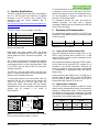
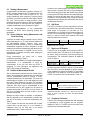
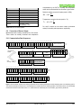
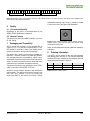
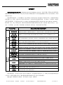
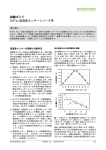
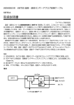
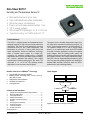
Data Sheet SHTC1 Humidity and Temperature Sensor IC Best performance-to-price ratio Fully calibrated and reflow solderable Ultra-low power consumption Power-up and measurement within 1 ms 1.8 V supply voltage Ultra-small DFN package: 2 × 2 × 0.75 mm Typical accuracy: ±3 %RH and ±0.3 °C Product Summary The SHTC1 is a digital humidity and temperature sensor designed especially for high-volume consumer electronics applications. This sensor is strictly designed to overcome conventional limits for size, power consumption, and performance to price ratio in order to fulfill current and future requirements. Sensirion’s CMOSens® technology offers a complete sensor system on a single chip, consisting of a capacitive humidity sensor, a bandgap temperature sensor, analog and digital signal processing, A/D converter, calibration data memory, and a digital communication interface supporting I2C fast mode. The ultra-small, 2 × 2 × 0.75 mm3 DFN package enables applications in even the most limited of spaces. Block diagram Benefits of Sensirion’s CMOSens® Technology The sensor covers a humidity measurement range of 0 to 100 %RH and a temperature measurement range of –30 to 100 °C with a typical accuracy of ±3 %RH and ±0.3°C. The operation voltage of 1.8 V and an energy budget below 1 µJ per measurement make the SHTC1 suitable for mobile or wireless applications running on the tightest power budgets. With the industry-proven quality and reliability of Sensirion’s humidity and temperature sensors and constant accuracy over a large measurement range, the SHTC1 offers an unprecedented performance-to-price ratio. Tape and reel packaging together with suitability for standard SMD assembly processes make the SHTC1 predestined for high-volume applications. High reliability and long-term stability Industry-proven technology with a track record of more than 10 years Designed for mass production Optimized for lowest cost Low signal noise RH sensor T sensor Signal conditioning Signal conditioning analog ADC digital Contents of this Data Sheet 1 Humidity and Temperature Sensor Specifications ............ 2 2 Electrical Specifications .................................................... 3 3 Timing Specifications ........................................................ 4 4 Interface Specifications ..................................................... 6 5 Operation and Communication ......................................... 6 6 Quality ............................................................................... 9 7 Packaging and Traceability ............................................... 9 8 Ordering Information ......................................................... 9 9 Technical Drawings ......................................................... 10 10 Further Information.......................................................... 12 Important Notices...................................................................... 14 www.sensirion.com Data processing and system control Calibration mem. VDD VSS I2C interface SDA SCL Figure 1 Functional block diagram of the SHTC1. Version 3 – May 2014 1/14 1 Humidity and Temperature Sensor Specifications Relative Humidity Temperature Parameter Accuracy tolerance1 Conditions Value Units Typ. 3.0 see Figure 2 0.1 0.01 %RH 1 0 to 100 %RH Resolution3 Specified range4 %RH Response time8 8 s Long-term drift <0.25 %RH/y Resolution3 Max. - Hysteresis - Repeatability2 Specified range4 extended5 time6 63% Typ. Response Long-term drift7 %RH %RH %RH Parameter Conditions Value Units Typ. 0.3 see Figure 3 0.1 0.01 –30 to +100 °C <5 to 30 s <0.02 °C/y Accuracy tolerance1 Max. - Repeatability2 63% Typ. 9 °C °C °C °C Table 2 Temperature sensor specifications. Table 1 Humidity sensor specifications. ΔT [C] ΔRH [%RH] ±2 ±10 Maximum Accuracy Maximum accuracy ±8 Typical Accuracy Typical Accuracy ±1.5 ±6 ±1 ±4 ±0.5 ±2 ±0 0 10 20 30 40 50 60 70 80 90 ±0 100 -30 Relative humidity [%RH] Figure 2 Typical and maximal tolerance for relative humidity in %RH at 25 °C. -10 10 30 50 70 90 Temperature [°C] Figure 3 Typical and maximal tolerance for temperature sensor in °C. 1 For definition of typ. and max. accuracy tolerance, please refer to the document “Sensirion Humidity Sensor Specification Statement”. 2 The stated repeatability is 3 times the standard deviation (3σ) of multiple consecutive measurement values at constant conditions and is a measure for the noise on the physical sensor output. 3 Resolution of A/D converter. 4 Specified range refers to the range for which the humidity or temperature sensor specification is guaranteed. 5 For details about recommended humidity and temperature operating range, please refer to section 1.1. 6 Time for achieving 63% of a humidity step function, valid at 25°C and 1 m/s airflow. Humidity response time in the application depends on the design-in of the sensor. 7 Typical value for operation in normal RH/T operating range. Max. value is < 0.5 %RH/y. Value may be higher in environments with vaporized solvents, outgassing tapes, adhesives, packaging materials, etc. For more details please refer to Handling Instructions. www.sensirion.com 8 Temperature response time depends on heat conductivity of sensor substrate and design-in of sensor in application. 9 Max. value is < 0.04°C/y. Version 3 – May 2014 2/14 1.2 Recommended Operating Conditions 1.1 RH Accuracy at Various Temperatures The sensor shows best performance when operated within recommended normal temperature and humidity range of 5 – 60 °C and 20 – 80 %RH, respectively. Long term exposure to conditions outside normal range, especially at high humidity, may temporarily offset the RH signal (e.g. +3%RH after 60h at >80%RH). After returning into the normal temperature and humidity range the sensor will slowly come back to calibration state by itself. Prolonged exposure to extreme conditions may accelerate ageing. Relative Humidity [%RH] Typical RH accuracy at 25°C is defined in Figure 2. For other temperatures, typical accuracy has been evaluated to be as displayed in Figure 4. 100 90 80 70 60 50 40 30 20 10 0 ±4.5 ±4.5 ±4 ±4 ±3.5 ±3.5 ±3.5 ±3.5 ±3.5 ±4 ±4.5 ±4 ±4 ±3.5 ±3.5 ±3 ±3 ±3 ±3 ±3.5 ±4 ±4.5 ±4 ±3.5 ±3 ±3 ±3 ±3 ±3 ±3 ±3 ±3.5 ±4 0 10 20 ±4 ±3.5 ±3 ±3 ±3 ±3 ±3 ±3 ±3 ±3.5 ±4 ±4 ±3.5 ±3 ±3 ±3 ±3 ±3 ±3 ±3 ±3.5 ±4 ±4 ±3.5 ±3.5 ±3 ±3 ±3 ±3 ±3 ±3 ±3.5 ±4 ±4.5 ±4 ±3.5 ±3.5 ±3 ±3 ±3 ±3 ±3 ±3.5 ±4 30 40 50 60 Temperature [°C] ±5 ±4.5 ±4 ±3.5 ±3.5 ±3 ±3 ±3 ±3 ±3.5 ±4 ±5 ±5 ±4.5 ±4 ±3.5 ±3.5 ±3 ±3 ±3 ±3.5 ±4 70 80 To ensure stable operation of the humidity sensor, the conditions described in the document “SHTxx Assembly of SMD Packages”, section “Storage and Handling Instructions” regarding exposure to volatile organic compounds have to be met. Please note as well that this does apply not only to transportation and manufacturing, but also to operation of the SHTC1. Figure 4 Typical accuracy of relative humidity measurements given in %RH for temperatures 0 – 80°C. 2 Electrical Specifications 2.1 Electrical Characteristics Default conditions of 25 °C and 1.8 V supply voltage apply to values in the table below, unless otherwise stated. Parameter Supply voltage Power-up/down level Symbol VDD VPOR Supply current IDD Conditions Min 1.62 1.05 - Typ. 1.8 1.2 0.7 Max 1.98 1.35 2.2 Measurement - 385 465 Average - 4.8 - - 8.6 - - 0.3 VDD VDD(max) + 0.5 0.2 VDD Static power supply Idle state Average power consumption - Average Low level input voltage VIL - -0.5 High level input voltage VIH - 0.7 VDD Low level output voltage VOL 3 mA sink current - Units V V µA Comments Average current consumption µA while sensor is measuring10 Average current consumption µA (continuous operation with one measurement per second)10 Average power consumption µW (continuous operation with one measurement per second)10 V V - - - Table 3 Electrical specifications. 10 These values can be reduced by using the low power measurement mode, see separate application note. www.sensirion.com Version 3 – May 2014 3/14 2.2 Absolute Maximum Ratings Stress levels beyond those listed in Table 4 may cause permanent damage to the device. These are stress ratings only and functional operation of the device at these conditions cannot be guaranteed. Exposure to the absolute maximum rating conditions for extended periods may affect the reliability of the device. Parameter Supply voltage, VDD Operating temperature range Storage temperature range11 ESD HBM ESD MM ESD CDM Latch up, JESD78 Class II, 125°C Rating -0.3 to +2.16 V -40 to +125 °C -40 to +125 °C 2 kV 200 V 500 V 100mA Table 4 Absolute maximum ratings. 3 Timing Specifications 3.1 Sensor System Timings Default conditions of 25 °C and 1.8 V supply voltage apply to values the table below, unless otherwise stated. Max. values are measured at -30°C and 1.98V supply voltage. Parameter Symbol Conditions Min. Typ. Max. Power-up time tPU After hard reset, VDD ≥ VPOR - 182 239 Soft reset time tSR After soft reset. - 173 230 Measurement duration tMEAS - - 10.8 14.4 Units Comments Time between VDD reaching VPU µs and sensor entering idle state Time between ACK of soft reset µs command and sensor entering idle state Duration for a humidity and ms temperature measurement12 Table 5 System timing specifications. 11 The recommended storage temperature range is 10-50°C. Please consult the document “SHTxx Handling Instructions” for more information. 12 These values can be reduced by using the low power measurement mode, see separate application note. www.sensirion.com Version 3 – May 2014 4/14 3.2 Communication Timings Default conditions of 25 °C and 1.8 V supply voltage apply to values in the table below, unless otherwise stated. Parameter SCL clock frequency Hold time (repeated) START condition LOW period of the SCL clock HIGH period of the SCL clock Set-up time for a repeated START condition SDA hold time SDA set-up time SCL/SDA rise time Symbol fSCL Min. 0 Typ. - Max. 400 0.6 - - µs - tLOW tHIGH Conditions After this period, the first clock pulse is generated - 1.3 0.6 - - µs µs - tSU;STA - 0.6 - - µs - tHD;DAT tSU;DAT tR - - 300 ns ns - SCL/SDA fall time tF - - 300 ns - SDA valid time Set-up time for STOP condition Capacitive load on bus line tVD;DAT - 0 100 20 20 * (VDD/5.5) - - 0.9 µs - tSU;STO - 0.6 - - µs - CB - - - 400 pF - tHD;STA Units Comments kHz - Table 6 Communication timing specifications. The numbers above are values according to the I2C specification. 1/fSCL tHIGH tR tLOW tF 70% SCL tSU;DAT 30% tHD;DAT DATA IN 70% SDA 30% tVD;DAT DATA OUT tF tR 70% SDA 30% Figure 5 Timing diagram for digital input/output pads. SDA directions are seen from the sensor. Bold SDA lines are controlled by the sensor, plain SDA lines are controlled by the micro-controller. Note that SDA valid read time is triggered by falling edge of preceding toggle. www.sensirion.com Version 3 – May 2014 5/14 4 Interface Specifications The SHTC1 supports I2C fast mode (SCL clock frequency from 0 to 400 kHz) with clock stretching. For detailed information on the I2C protocol, refer to NXP I2C-bus specification and user manual UM10204, Rev. 4, February 13, 2012: http://ics.nxp.com/support/documents/interface/pdf/I2C.bu s.specification.pdf The SHTC1 comes in a 4-pin package – see Table 7. Pin Name Comments 1 VDD Supply voltage 2 SCL Serial clock, bidirectional 3 SDA Serial data, bidirectional 4 VSS Ground 1 2 SHTC1 AXY89 4 3 SHTC1 I2C SCL is used to synchronize the communication between microcontroller and the sensor. The master must keep the clock frequency within 0 to 400 kHz as specified in Table 6. The SHTC1 may pull down the SCL line when clock stretching is enabled. The SDA pin is used to transfer data in and out of the sensor. For safe communication, the timing specifications defined in the I2C manual must be met. To avoid signal contention, the microcontroller must only drive SDA and SCL low. External pull-up resistors (e.g. 10 kΩ) are required to pull the signal high. For dimensioning resistor sizes please take bus capacity requirements into account. It should be noted that pull-up resistors may be included in I/O circuits of microcontrollers. VDD SCL IN RP SHTC1 (slave) SDA SHTC1 SDA IN AXY89 SCL OUT C = 100 nF SCL Operation and Communication All commands and memory locations of the SHTC1 are mapped to a 16-bit address space which can be accessed via the I2C protocol. Power-supply pins supply voltage (VDD) and ground (VSS) must be decoupled with a 100 nF capacitor that shall be placed as close to the sensor as possible – see Figure 6. RP For mechanical reasons the center pad should be soldered. Electrically, the center pad is internally connected to GND and may be connected to the GND net on the PCB or left floating. 5 Table 7 SHTC1 pin assignment (top view). The center pad is internally connected to VSS. MCU (master) For good performance of the SHTC1 in the application, it is important to know that the center pad of the SHTC1 offers the best thermal contact to the temperature sensor. For more information on design-in, please refer to the document “SHTxx Design Guide”. SDA OUT address Bin. Dec. Hex. 111’0000 112 0x70 Table 8 SHTC1 I2C device address. 5.1 Power-Up and Communication Start Upon VDD reaching the power-up voltage level VPOR, the SHTC1 enters idle state after a duration of tPU. In idle state, the SHTC1 is ready to receive commands from the master (microcontroller). Each transmission sequence begins with START condition (S) and ends with an (optional) STOP condition (P) as described in the I2C-bus specification. Whenever the sensor is powered up, but not performing a measurement or communicating, it automatically enters idle state for energy saving. Please note that in case VDD is set to 0 V (GND), e.g. in case of a power off of the SHTC1, the SCL and SDA pads are also pulled to GND. Consequently, the I2C bus is blocked while VDD of the SHTC1 is set to 0 V. 5.2 Measurement Commands The SHTC1 provides the possibility to define the sensor behavior during measurement as well as the transmission sequence of measurement results. These characteristics are defined by the appropriate measurement command (see Table 9). Each measurement command triggers both a temperature and a humidity measurement. Clock Stretching Enabled Read T Read H First First Clock Stretching Disabled Read T Read H First First 0x7CA2 0x7866 0x5C24 0x58E0 Table 9 Measurement commands. GND Figure 6 Typical application circuit, including pull-up resistors RP and decoupling of VDD and VSS by a capacitor. www.sensirion.com Version 3 – May 2014 6/14 5.3 Starting a Measurement A measurement communication sequence consists of a START condition followed by the I2C header with the 7-bit I2C device address and a write bit (write W: ‘0’). The sensor indicates the proper reception of a byte by pulling the SDA pin low (ACK bit) after the falling edge of the 8th SCL clock. Then the sensor is ready to receive a 16-bit measurement command. Again, the SHTC1 acknowledges the proper reception of each byte with ACK condition. A complete measurement cycle is presented in Figure 7. With the acknowledgement of the measurement command, the SHTC1 starts measuring humidity and temperature. 5.4 Sensor Behavior during Measurement and Clock Stretching In general, the sensor does not respond to any I2C activity during measurement, i.e. I2C read and write headers are not acknowledged (NACK). However, when clock stretching has been enabled by using a corresponding measurement command, the sensor responds to a read header with an ACK and subsequently pulls down the SCL line until the measurement is complete. As soon as the measurement is complete, the sensor starts sending the measurement results. During measurement, the sensor has a current consumption according to Table 3. For best possible repeatability of humidity and temperature measurements, it is recommended to avoid any communication on the I2C bus while the SHTC1 is measuring. For more information, see application note “SHTC1 Optimization of Repeatibility”. 5.5 Readout of Measurement Results After a measurement command has been issued and the sensor has completed the measurement, the master can read the measurement results by sending a START condition followed by an I2C read header. The sensor will acknowledge the reception of the read header and send two bytes of data followed by one byte CRC checksum and another two bytes of data followed by one byte CRC checksum. Each byte must be acknowledged by the microcontroller with an ACK condition for the sensor to continue sending data. If the SHTC1 does not receive an ACK from the master after any byte of data, it will not continue sending data. Whether the sensor sends out humidity or temperature data first depends on the measurement command that was sent to the sensor to initiate the measurement (see Table 9). The I2C master can abort the read transfer with a NACK condition after any data byte if it is not interested in subsequent data, e.g. the CRC byte or the second measurement result, in order to save time. www.sensirion.com In case the user needs humidity and temperature data but does not want to process CRC data, it is recommended to read the first two bytes of data with the CRC byte (without processing the CRC data) and abort the read transfer after reading the second two data bytes with a NACK. This procedure is more time efficient than starting two different measurements and aborting the read transfer after the first two data bytes each time. 5.6 Soft Reset The SHTC1 provides a soft reset mechanism that forces the system into a well-defined state without removing the power supply. If the system is in idle state (i.e. if no measurement is in progress) the soft reset command can be sent to SHTC1 according to Figure 8. This triggers the sensor to reset all internal state machines and reload calibration data from the memory. Command Software reset Hex. Code 0x805D Bin. Code 1000’0000’0101’1101 Table 10 Soft reset command. 5.7 Read-out of ID Register The SHTC1 has an ID register which contains an SHTC1specific product code. The read-out of the ID register can be used to verify the presence of the sensor and proper communication. The command to read the ID register is shown in Table 11. Command Hex. Code Bin. Code Read ID register 0xEFC8 1110’1111’1100’1000 Table 11 Read-out command of ID register. It needs to be sent to the SHTC1 after an I2C write header. After the SHTC1 has acknowledged the proper reception of the command, the master can send an I2C read header and the SHTC1 will submit the 16-bit ID followed by 8 bits of CRC. The structure of the ID is described in Table 12. 16-bit ID xxxx'xxxx’xx 00’0111 bits 5 to 0: SHTC1-specific product code bits 15 to 6: unspecified information Table 12 Structure of the 16-bit ID. Bits 15:6 of the ID contain unspecified information (marked as “x”), which may vary from sensor to sensor, while bits 5:0 contain the SHTC1-specific product code. 5.8 Checksum Calculation The 8-bit CRC checksum transmitted after each data word is generated by a CRC algorithm with the properties displayed in Table 13. The CRC covers the contents of the two previously transmitted data bytes. Version 3 – May 2014 7/14 Property Value Name Width Polynomial Initialization Reflect input Reflect output Final XOR Examples CRC-8 8 bits 0x31 (x8 + x5 + x4 + 1) 0xFF False False 0x00 CRC (0x00) = 0xAC CRC (0xBEEF) = 0x92 compensated by the SHTC1. Humidity and temperature values can be calculated with the formulas in given below. Relative humidity conversion formula (result in %RH): RH 100 SRH 2 16 Temperature conversion formula (result in °C): T 45 175 ST 2 16 SRH and ST denote the raw sensor output (as decimal values) for humidity and temperature, respectively. Table 13 SHTC1 I2C CRC properties. 5.9 Conversion of Sensor Output Measurement data is always transferred as 16-bit values. These values are already linearized and temperature 5 6 7 8 9 S 1 1 1 0 0 0 0 0 10 I2C address + write clock stretching disabled 11 12 13 14 15 16 17 0 1 0 1 1 1 0 0 18 Measurement command MSB 29 30 31 32 33 34 35 36 37 19 20 21 22 23 24 25 26 0 0 1 0 0 1 0 0 27 28 P Measurement command LSB 38 39 S 1 1 1 0 0 0 0 1 I2C repeated address + read while meas. is in prog. (polling) Measurement in progress 40 P SHTC1 measuring SHTC1 in idle state measurement cont’d measurement completed SHTC1 measuring 41 42 43 44 45 46 47 48 S 1 1 1 0 0 0 0 1 49 ACK 4 ACK 3 NACK 2 ACK 1 ACK 5.10 Communication Data Sequences I2C address + read clock stretching enabled S 1 1 1 0 0 0 0 1 ACK 29 30 31 32 33 34 35 36 37 38 I2C address + read while meas. is in progress SHTC1 measuring, SCL line pulled low measurement continued Humidity MSB Humidity LSB 0 0 0 1 1 1 0 0 ACK 0 0 1 1 0 0 1 1 ACK 1 0 1 0 0 0 0 1 ACK 50 51 52 53 54 55 56 57 58 59 60 61 62 63 64 65 66 67 68 69 70 71 72 73 74 75 76 Humidity CRC checksum Temperature MSB Temperature LSB 1 1 0 0 0 1 1 1 ACK 1 0 0 0 1 0 1 1 ACK 0 1 1 0 0 1 0 0 ACK 77 78 79 80 81 82 83 84 85 86 87 88 89 90 91 92 93 94 95 96 97 98 99 100 101 102 103 104 P Temperature CRC checksum Figure 7 Communication sequence for starting a measurement and reading measurement results displaying both clock stretching options. The numerical example corresponds to a read humidity-first command with clock stretching enabled. The physical values of the transmitted measurement results are 65.6 %RH and 23.7 °C. Clear blocks are controlled by the microcontroller, grey blocks by the SHTC1. www.sensirion.com Version 3 – May 2014 8/14 4 5 6 7 8 S 1 1 1 0 0 0 0 0 9 10 11 12 13 14 15 16 17 1 0 0 0 0 0 0 0 I2C address + write 18 26 27 28 0 1 0 1 1 1 0 1 ACK 3 ACK 2 ACK 1 19 P Command MSB 20 21 22 23 24 25 Command LSB Figure 8 Command access communication sequence. The example shows a soft reset command. Clear blocks are controlled by the microcontroller, grey blocks by the SHTC1. 6 alphanumeric tracking code. The pin-1 indicator is located in the top left corner. See Figure 9 for illustration. Quality 6.1 Environmental Stability SHTC1 Qualification of the SHTC1 is performed based on the JEDEC JESD47 qualification test method. 6.2 Material Contents The device is fully RoHS and WEEE compliant, e.g. free of Pb, Cd, and Hg. 7 Packaging and Traceability SHTC1 sensors are provided in a DFN package with an outline of 2 × 2 × 0.75 mm3 and a terminal pitch of 1 mm. DFN stands for dual flat no leads. The humidity sensor opening is centered on the top side of the package. The sensor chip is made of silicon and is mounted to a lead frame. The latter is made of Cu plated with Ni/Pd/Au. Chip and lead frame are overmolded by a green epoxybased mold compound. Please note that the side walls of sensor are diced and therefore these diced lead frame surfaces are not covered with the respective plating. The Moisture Sensitivity Level classification of the STSC1 is MSL1, according to IPC/JEDEC J-STD-020. All SHTC1 sensors are laser marked for easy identification and traceability. The marking on the sensor consists of two lines and a pin-1 indicator. The top line contains the sensor type (SHTC1), the bottom line contains a 5-digit, www.sensirion.com XXXXX Figure 9 Laser marking on SHTC1, the top line with the pin-1 indicator and the sensor type, the bottom line with the 5-digit alphanumeric tracking code. Reels are also labeled and provide additional traceability information. 8 Ordering Information The SHTC1 can be ordered in tape and reel packaging with different sizes, see Table 14. The reels are sealed into antistatic ESD bags. A drawing of the packaging tape with sensor orientation is shown in Figure 12. Quantity Packaging 1’000 Tape & Reel 10’000 Tape & Reel Reel Diameter Order Number 180 mm (7 inch) 1-101110-01 330 mm (13 inch) 1-100925-01 Table 14 SHTC1 ordering options. Version 3 – May 2014 9/14 9 Technical Drawings 9.1 Package Outline 0.35 1 2 0.2x45° 0.7 0.35 0.75 1.6 2 * Mold opening shows smooth transition to package surface. Therefore this dimension is not well defined and given for reference only. Figure 10 Package outline drawing of the SHTC1. Dimensions are given in millimeters. www.sensirion.com Version 3 – May 2014 10/14 9.2 Metal Land Pattern Figure 11 Recommended metal land pattern for SHTC1 (all dimensions are in mm). Recommended solder paste stencil thickness is 100µm, pads on PCB are recommended to be non solder mask defined (NSMD). 9.3 Tape and Reel Package Figure 12 Technical drawing of the packaging tape with sensor orientation in tape. Header tape is to the right and trailer tape to the left on this drawing. Dimensions are given in millimeters. www.sensirion.com Version 3 – May 2014 11/14 10 Further Information For more in-depth information on the SHTC1 and its application please consult the following documents: Document Name Description Source Available for download from the SHTC1 product SHTxx Assembly of SMD Instructions on soldering and processing of the website: Packages SHTC1 in a production environment www.sensirion.com/shtc1 Available for download from the SHTC1 product SHTC1 Optimization of Measures for optimization of repeatability of website: Repeatibility sensor output. www.sensirion.com/shtc1 Available for download from the SHTC1 product SHTC1 Low Power Measurement Description of SHTC1 low power measurement website: Mode mode. www.sensirion.com/shtc1 Available for download at the Sensirion humidity Design guidelines for designing SHTxx humidity SHTxx Design Guide sensors download center: sensors into applications www.sensirion.com/humidity-download Available for download at the Sensirion humidity Guidelines for proper handling of SHTxx humidity SHTxx Handling Instructions sensors download center: sensors www.sensirion.com/humidity-download Available for download at the Sensirion humidity Sensirion Humidity Sensor Definition of sensor specifications. sensors download center: Specification Statement www.sensirion.com/humidity-download Table 15 Documents containing further information relevant for the SHTC1. www.sensirion.com Version 3 – May 2014 12/14 Revision History Date February 21, 2013 May 21, 2013 May 23, 2014 www.sensirion.com Version 1 2 3 Page(s) all 6, 8 1-4, 7, 9, 1112 Changes Initial version Section 5.2.1 removed, stop condition added to fig. 6 RH accuracy at various temperatures added, MSL added, ordering information added, metal land pattern added, minor adjustments. Version 3 – May 2014 13/14 Important Notices Warning, Personal Injury Do not use this product as safety or emergency stop devices or in any other application where failure of the product could result in personal injury. Do not use this product for applications other than its intended and authorized use. Before installing, handling, using or servicing this product, please consult the data sheet and application notes. Failure to comply with these instructions could result in death or serious injury. If the Buyer shall purchase or use SENSIRION products for any unintended or unauthorized application, Buyer shall defend, indemnify and hold harmless SENSIRION and its officers, employees, subsidiaries, affiliates and distributors against all claims, costs, damages and expenses, and reasonable attorney fees arising out of, directly or indirectly, any claim of personal injury or death associated with such unintended or unauthorized use, even if SENSIRION shall be allegedly negligent with respect to the design or the manufacture of the product. ESD Precautions The inherent design of this component causes it to be sensitive to electrostatic discharge (ESD). To prevent ESD-induced damage and/or degradation, take customary and statutory ESD precautions when handling this product. See application note “ESD, Latchup and EMC” for more information. Warranty SENSIRION warrants solely to the original purchaser of this product for a period of 12 months (one year) from the date of delivery that this product shall be of the quality, material and workmanship defined in SENSIRION’s published specifications of the product. Within such period, if proven to be defective, SENSIRION shall repair and/or replace this product, in SENSIRION’s discretion, free of charge to the Buyer, provided that: notice in writing describing the defects shall be given to SENSIRION within fourteen (14) days after their appearance; such defects shall be found, to SENSIRION’s reasonable satisfaction, to have arisen from SENSIRION’s faulty design, material, or workmanship; the defective product shall be returned to SENSIRION’s factory at the Buyer’s expense; and the warranty period for any repaired or replaced product shall be limited to the unexpired portion of the original period. This warranty does not apply to any equipment which has not been installed and used within the specifications recommended by SENSIRION for the intended and proper use of the equipment. EXCEPT FOR THE WARRANTIES EXPRESSLY SET FORTH HEREIN, SENSIRION MAKES NO WARRANTIES, EITHER EXPRESS OR IMPLIED, WITH RESPECT TO THE PRODUCT. ANY AND ALL WARRANTIES, INCLUDING WITHOUT LIMITATION, WARRANTIES OF MERCHANTABILITY OR FITNESS FOR A PARTICULAR PURPOSE, ARE EXPRESSLY EXCLUDED AND DECLINED. SENSIRION is only liable for defects of this product arising under the conditions of operation provided for in the data sheet and proper use of the goods. SENSIRION explicitly disclaims all warranties, express or implied, for any period during which the goods are operated or stored not in accordance with the technical specifications. SENSIRION does not assume any liability arising out of any application or use of any product or circuit and specifically disclaims any and all liability, including without limitation consequential or incidental damages. All operating parameters, including without limitation recommended parameters, must be validated for each customer’s applications by customer’s technical experts. Recommended parameters can and do vary in different applications. SENSIRION reserves the right, without further notice, (i) to change the product specifications and/or the information in this document and (ii) to improve reliability, functions and design of this product. Copyright © 2014, by SENSIRION. CMOSens® is a trademark of Sensirion All rights reserved Headquarters and Subsidiaries Sensirion AG Laubisruetistr. 50 CH-8712 Staefa ZH Switzerland Sensirion Inc., USA Phone: +1 805 409 4900 [email protected] www.sensirion.com Sensirion Korea Co. Ltd. Phone: +82 31 337 7700~3 [email protected] www.sensirion.co.kr Phone: +41 44 306 40 00 Fax: +41 44 306 40 30 [email protected] www.sensirion.com Sensirion Japan Co. Ltd. Phone: +81 3 3444 4940 [email protected] www.sensirion.co.jp Sensirion China Co. Ltd. Phone: +86 755 8252 1501 [email protected] www.sensirion.com.cn Sensirion AG (Germany) Phone: +41 44 927 11 66 [email protected] www.sensirion.com To find your local representative, please visit www.sensirion.com/contact www.sensirion.com Version 3 – May 2014 14/14 公司简介 深圳盛世物联科技有限公司(Shenzhen Sense IoT Technology Co.,Ltd)专业代理推广国际知名品牌环境传 感器及半导体元器件产品,是一家由多位环境科学领域的资深人士联合创建的集技术开发与代理分销为一体的 高新技术企业。 面向物联传感应用,公司长期致力于室内环境空气品质及有害气体监控产品的技术开发,并提供相关配套 的传感器、IC、模块、设备以及行业应用方案支持,技术应用涉及温湿度传感、压力传感、气体传感、加速度 传感等监测领域,产品涵盖 Freescale、TI、Sharp、GE(Amphenol)安费诺、Silicon Labs、PLX、Micron、Sensirion、 SenseAir、ST、City、Honeywell、Measurement(Humirel)精量等国际知名品牌,服务客户遍及石油化工、电力 电子、汽车智能、空气净化、楼宇暖通、医药监测、食品安全、现代农业等众多终端。 产品及子类 重点品牌及代表性物料型号 Sensirion/Silicon Labs/MEAS/ST/TI 等公司的 SHT1X/2X/7X 温湿一体系列,SI7020/21 系列, 温湿度传感器 PM2.5 粉尘 颗粒物传感器 环 境 CO2 二氧化 传 感 碳传感器 多参数环境 器 传感器模块 元 MSM-1401/1403/1405/1408/1411/1413/1415/1418 等集合温湿度、粉尘颗粒物、二氧化碳和 VOC 空气质量传感器的含 RS232/485/WIFI 接口的多参数环境传感器模块 电化学毒气 美国高顿公司的 CO2 传感器、CO 气体传感器、H2S 传感器、H2S 气体传感器、O2 传感器、氨 传感器 气传感器、氯气传感器、毒气传感器、有毒气体传感器、电化学气体传感器、电化学传感器等 CPU/MCU/ARM/DS KINETIS 微控制器(MK60DN512),MSP430 系列,C8051 系列,LPC 系列,STC 系列,PIC 系列 P 微处理器 Freescale 公司的 IMX 处理器(MCIMX536),STM32 系列,LPC2000/3000 系列嵌入式处理器 PCI-E 接口 体 GE 公司 T6613\T6615 二氧化碳模块、SenseAir 公司 K30/S8 模块、ELT 公司 B530 系列等模块 Sensirion /FSL 公司的 SDP600/1000/2000/1108/2108 系列,MPL 系列 MEMS 压力传感器系列 存储器 SDRAM 导 SHARP 公司的 GP2Y1010AU0F/GP2Y1050AU0F/GP2Y1051AU0F 及 GE 公司 SM-PWM-01A 等模块 差压传感器 数据转换器 ADC 半 HTU20/21D,HTS221、HDC1000/1008 系列, HYT221/271/939,铂电阻/NTC 热电阻/湿敏电阻等 TI/ADI 公司数据转换器全系列产品,典型的如 AFE5805ZCF、AD600 等 镁光/HYNIX 公司的 MT29F256/128/64 系列,H5DU 系列,FIFO 系列 PCI9054\PEX8112\8619\8632\8648,TL16C550/552/554/S5920/S5933 系列 TI 公司 CC3000\CC2530F256\CC2591\CC2540\CC1101 系列 WIFI 及 ZIGBEE 无线技术 无线连接 器 件 以太网口 USB 并口 SIMCOM 公司的 SIM900B\900A\900D\900S 等 GSM/GPRS 通讯模块 MARVELL 公司 88E 系列 PHY(以太网)收发器,88W 系列无线连接 DM9000\DM9161 系列、CS8900 系列、RTL8019\8139\8201 系列、LXT970/971 等 PHY 收发器 CY7C63001/68013/SL811,USBN9603/9604 及 PDIUSBD12 系列 USB 接口器件 RS232/485 RS232/422/485 系列接口器件,FT232 等串口产品 电源芯片 Micrel 全系列电源芯片;DIALOG 公司 DA9053-3HHA1/FHA1 系列可编程电源,与 FSL 的 (可编程) IMX515/535/536 系列处理器搭配使用 盛世物联拥有一支经验丰富的专业技术/营销团队,以快速响应您的需求,并一如既往的为您提供最先进的 产品技术、最优化的解决方案、最快捷的物流服务和最具竞争力的产品价格服务。 盛世追梦,物联你我!感谢亲一直以来的大力支持,祝商祺! Tel: 0755-61288164 89605981 89533801 Fax:0755-61288174 WWW.SENSEIOT.COM V1.0 2014.12