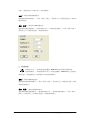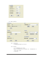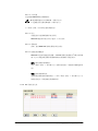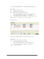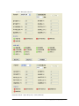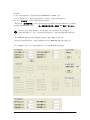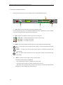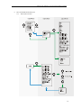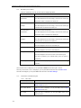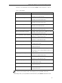
1
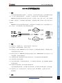
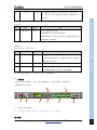
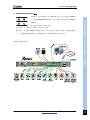
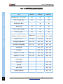
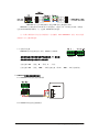
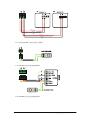
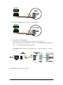
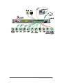
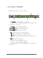
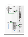
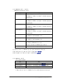
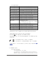
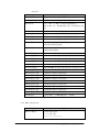
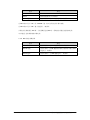
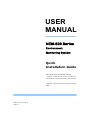
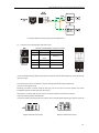
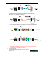
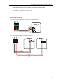
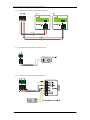
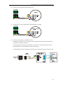
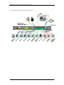
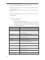
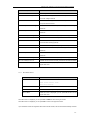
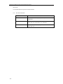
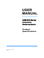
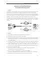
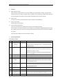
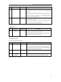
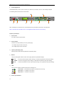
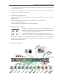
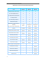
USER
MANUAL
NEM-500 系列
环境监控系统
Ⅰ 产品规格书
产品的功能规格说明
Ⅱ 快速安装指南
产品硬件安装所需的信息
Ⅲ 软件使用手册
监控单元与上位机的软件使用说明
Shenzhen ZhongNai Industry Co., Ltd.
Edited By Faye
Approved By David
http://www.zhongnai.net
+86-755-26832277
¬ +86-755-26887599
USER
MANUAL
NEM-500 系列
环境监控系统
产品规格书
Manual V1.3.0, 2011-07-14
Shenzhen ZhongNai Industry Co., Ltd.
PCB V1.3
http://www.zhongnai.net
+86-755-26832277
¬ +86-755-26887599
NEM-500 系列环境监控系统
NEM-500 系列环境监控系统
1.
概述
单元,专门用于对通信行业的基站、一体化机房、户外柜进行环境、设备控制和远程监视。
NEM-500 为你监视重要的环境因素与安全状况,比如温度、湿度、烟雾、水浸、门禁、震动/倾
斜、MDF、防雷器等。当传感器超出设置的阀值时,系统将通过 LCD、蜂鸣器、系统日志等多种方
式提醒你。
NEM-500 同时具备完善的设备检测功能,可以检测如开关电源的运行状态。通过预留的自定义
接口(可选),也可以连接其它干接点输出型的传感器。
2.
特点
2.1 前维护方式(前接线方式)。提高空间利用率,维护更方便。
ENVIRONMENT MONITORING SYSTEM
本环境监控系统是为通信行业基站、一体化机房、户外柜所开发的小型化、高可靠性的环境监控
2.2 结构紧凑:1U/19”标准机箱,安装十分方便。
2.3 监控机柜开关电源。NEM-500 可以与开关电源互联,支持数据透明传输转发。完整的监控功能,
必须提供通信协议另行开发。
2.4 标准电总协议上传。NEM-500 按照规定的协议通过干接点、RS485/232/IP 方式向监控后台上传
环境量数据、接受远程系统指令。
2.5 完善的监控功能:智能控制机房内的各种环境设备,自动远程监测环境参数和报警量。
2.6 直观易用的上位机控制软件。
2.7 支持众多的传感器:可以连接模拟量输出、开关量输出的各种传感器,也支持 RS232、RS485
接口的传感器。
2.8 内置部分常用的传感器,减少安装监控系统的布线。
可选内置倾斜震动传感器、直流电源失效告警传感器、交流电源失效告警传感器、水浸传感器。
2.9 灵活的供电方式:交流或直流供电,交流供电电压范围:85~300Vac,直流供电电压范围:
20~60Vdc。
3.
功能
Shenzhen ZhongNai Industry Co., Ltd.
http://www.zhongnai.net
86-755-26832277
1
NEM-500 系列环境监控系统
z
信号采集功能
采集环境变量(如温湿度、烟雾等)、设备变量(如开关电源等)数据,经过 MCU 处理、分析,
最终在本机 LCD 或远程计算机上为你呈现整个机房的状态;
z
报警功能
ENVIRONMENT MONITORING SYSTEM
用户指定传感器的监控参数,如果现场读数超越限制,系统将发出告警信号;
z
历史记录功能
供用户回溯查询历史告警信息。
z
本地或远程控制功能
本地可以通过前面板上的按键进行参数、数据查询和设置等;
通过以太网(IP 协议)/RS232/RS485/干接点接口与上位计算机进行通讯,上位机可以远程读取
监控单元的所有状态数据和修改系统设置。
可以选择使用中鼐自主的通讯协议及上位机远程控制软件。
4.
产品规格
环境变量
序号
变量
规格
1
温度/湿度
4路
描述
4 路模拟 4~20mA 电流型传感器;
可支持 2 路温湿度组合传感器,或 4 路单温度传感器。
2
水浸
2路
检测是否发生漏水、淹水状况。
1 路内置,传感器电路已经内置,机箱外部仅需要连接电极;
1 路外置,连接至外部的水浸传感器(干接点)。
3
门禁
1路
检测门的状态(打开/关闭)。
4
烟雾
1路
检测是否产生烟雾、火灾。
5
交流电源失效告警
1路
检测单相交流电压是否在正常范围内。
1 路内置,需要连接交流电源线至本机检测端子;
6
直流电源失效告警
1路
检测直流电压是否在正常范围内。
1 路内置,需要连接直流电源线至本机检测端子;
7
防雷器
1路
检测避雷器的状态(干接点)。
8
MDF
1路
检测配线架的状态。
9
倾斜震动
1路
检测机柜是否发生倾斜、震动或撞击。
内置,不需要外部连线。
10
开关电源
1路
检测开关电源的运行状态(标准配置为 RS485 连接)。
用户可选 RS232 串口连接(通过 RS485-RS232 转换器)。
支持数据透明传输转发。完整的监控功能,必须提供通信
协议另行开发。
2
Shenzhen ZhongNai Industry Co., Ltd.
http://www.zhongnai.net
86-755-26832277
NEM-500 系列环境监控系统
11
2路
自定义
一路默认配置为连接开关电源失效告警(干接点接口);
另一路为用户自定义连接其它类型的干接点传感器,带
12V 供电。
序号
变量
规格
1
干接点输出
8路
描述
用户自定义输出信号类型。
O1/O2/O3/O4 为小电流信号输出接口;
O5/O6/O7/O8 为大电流信号输出接口,继电器触点容量为
5A 250Vac,5A 30Vdc。
通讯接口
配置 4 个端口,分配方式如下:
序号
接口类型
规格
1
RS485
2路
描述
连接 RS485 接口的智能设备。
支持数据透明传输转发。完整的监控功能,必须提供
通信协议另行开发。
2
Ethernet
3
RS485/232 复用
1 路(可选) 通过 TCP/IP 连接远程的计算机或告警中心
1路
连接远程的计算机或告警中心
在 RS232/RS485 之间切换(默认 RS485)
注:2/3 不能同时使用,同一时间只允许其中一种连接方式。
5.
ENVIRONMENT MONITORING SYSTEM
输出接口
产品外观
机箱为 1U 高(43.6mm),19 英寸宽(482.6mm),深度 122mm,前接线方式。
机箱前面板参考示意图:
注:示意图并非按实物比例。
注:在本文档中,变送器、传感器、一体化变送器,以上 3 个术语通用。
接口规格:
Shenzhen ZhongNai Industry Co., Ltd.
http://www.zhongnai.net
86-755-26832277
3
NEM-500 系列环境监控系统
1) 电源开关
打开/关闭本设备的电源。
2) 电源接口
ENVIRONMENT MONITORING SYSTEM
可选交流电源或直流电源为本机供电。
交流供电允许电压范围:85~300Vac;
直流供电电压范围:20~60Vdc。
3) LCD 液晶显示屏
显示传感器的状态数据,显示参数设置界面。
4) 按键:
配合 LCD 液晶显示屏使用,用于菜单翻页、参数设置。
UP
—— 向上翻页(查看时),或参数增加(设置时);
DOWN —— 向下翻页(查看时),或参数减小(设置时);
OK
—— 确认键,选择当前菜单项目(查看时),或确认参数(设置时)。
5) LED 指示灯
显示监控单元的运行状态及告警状态。
电源指示 —— 指示本设备处于电源接通、运行状态;
普通告警 —— 指示当前发生告警,等级为普通。
重要告警 —— 指示当前发生告警,等级为严重;
6) 传感器输入接口
4 路电流型模拟信号输入,12Vdc 供电接口,连接温度/温湿度传感器,或同类型接口的其它
传感器,如电流传感器、压力传感器等;
8 路开关量信号(干接点)输入,其中 3 路带 12Vdc 供电接口,连接如门禁、烟雾探测器、红
外探测器、防雷器等传感器;
干接点输入接口,可以通过并联(常开输出)、或串联(常闭输出)方式扩展连接多个传感器。
7) 干接点(继电器)输出接口
8 路接口,用于将告警信号输出至上级的报警中心,或控制设备的启动/停止。
用户可以自定义告警规则,自由配置任一告警信号联动 O1~O8 继电器动作。
O1~O4 路端口用于提供开关量信号输出;
O5~O8 路端口可以直接控制风扇、加热器等大电流设备。
4
Shenzhen ZhongNai Industry Co., Ltd.
http://www.zhongnai.net
86-755-26832277
NEM-500 系列环境监控系统
8) RS485/RS232/Ethernet 接口
4 路接口:A 为可选的以太网(Ethernet)接口;B、C 为固定 RS485 接
口;D 为 RS485/RS232 复用接口,可以自由设置接口类型为 RS485 或
A、D 接口为系统自动识别切换。
A、D 接口,用于连接上位计算机,或告警中心设备;
B、C 接口,用于连接 RS485 接口的其它设备,如开关电源、空调、热交换器、温湿度传感器等。
(注:支持数据透明传输转发。完整的监控功能,必须提供通信协议另行开发。)
配置与电缆连线示意图:
Shenzhen ZhongNai Industry Co., Ltd.
http://www.zhongnai.net
86-755-26832277
ENVIRONMENT MONITORING SYSTEM
RS232。
5
NEM-500 系列环境监控系统
NEM-500 系列环境监控系统规格对照表
ENVIRONMENT MONITORING SYSTEM
6
型号
NEM-510
NEM-520
NEM-530
模拟量输入接口(4~20mA 电流)
4路
4路
4路
干接点/开关量 输入接口
8路
8路
8路
交流电压检测(单相)
/
1路
1路
直流电压检测
1路
1路
1路
干接点(继电器)输出接口
8路
8路
8路
RS485 接口(固定)
2路
2路
2路
1路
1路
RS485/232 复用
RS485/232 复用
RS485/RS232 复用接口,上传
(可选择 RS485 或 RS232 工作方式)
1 路固定 RS485
以太网(Ethernet)
1 路,可选
1 路,可选
1 路,可选
增加选配的倾斜震动模块
支持,可选
支持,可选
支持,可选
增加选配的水浸传感器模块
支持,可选
支持,可选
支持,可选
控制直排风扇
/
支持,可选
支持,可选
控制加热器
/
支持,可选
支持,可选
交流电源(220V)供电
支持,可选
支持,可选
支持,可选
直流电源(48V)供电
支持,可选
支持,可选
支持,可选
上位机监控软件
√
√
√
控制热交换器
/
/
支持,可选
监控空调
/
/
支持,可选
监控开关电源
/
/
支持,可选
监控智能空调遥控器
/
/
支持,可选
Shenzhen ZhongNai Industry Co., Ltd.
http://www.zhongnai.net
86-755-26832277
USER
MANUAL
NEM-500 系列
环境监控系统
快速安装指南
Manual V1.3, 2011-07-14
Shenzhen ZhongNai Industry Co., Ltd.
PCB V1.3
http://www.zhongnai.net
+86-755-26832277
¬ +86-755-26887599
本手册包含以下内容:
□ NEM-500 监控单元硬件安装说明,如何连接各类传感器至 NEM-500。如何连接 NEM-500 至上位
计算机。
□ 各类连接线的线序定义。
重要声明:
□ 本手册为该系列产品的综合性文档。本手册中述说的监控单元功能、截图中显示的功能并非在所
有产品中出现。每款最终产品的功能与配置请参见该产品的订货配置单/出货单。
版权声明:
Copyright © 2003-2011, Shenzhen ZhongNai Industry Co., Ltd., Printed in the P.R.C., All Rights
Reserved.
NEM-500 系列环境监控系统快速安装指南
1
1 安装
1.1 用螺钉将安装挂耳固定在外壳两端,然后将 NEM-500 安装固定到机架上。
1.2 NEM-500 外壳连接地线。
将 NEM-500 外壳背板左方的接地端子连接保护地线(PE)。
1.3 连接外部传感器至 NEM-500。
1.3.1 温湿度传感器(4~20mA 电流型模拟量接口)
本设备可连接 2 路两线制的电流型温湿度传感器,供电电压为 12Vdc。
标记“TEM1”的接口连接温度传感器;标记“HUM1”的接口连接湿度传感器。
注:选择固定温湿度传感器的位置非常重要,注意避开加热源或风扇的位置。
1.3.2 温湿度传感器(4~20mA 电流型模拟量接口)
本设备可连接 2 路两线制的电流型温湿度传感器,供电电压为 12Vdc。
标记“TEM2”的接口连接温度传感器;标记“HUM2”的接口连接湿度传感器。
1.3.3 水浸传感器 W1(内置传感器)
将检测电极片安装至被检测区域最低处;
连接检测电极片(2 线)至 W1 位置的两个 POLE 端口。电极片不分极性。
1.3.4 水浸传感器 W2(外置传感器)
连接传感器电源端口至 W2 位置对应的+12V 与 GND;
连接传感器干接点输出接口至 W2 位置的 SEN 与 GND。
默认连接端口类型为常开接口(正常时断开,告警时闭合)。
如果连接常闭型接口,必须通过后台软件配置端口类型为对应的常开/常闭。
1.3.5 门磁/门禁
连接门磁/门禁的干接点输出接口至 DOOR 位置的 CON 与 GND。
默认连接端口类型为常闭接口(正常时闭合,告警时断开)。
如果连接常开型接口,必须通过后台软件配置端口类型为对应的常开/常闭。
2
NEM-500 系列环境监控系统快速安装指南
1.3.6 烟雾传感器
连接传感器电源端口至 SMOKE 位置对应的+12V 与 GND;
连接烟雾传感器的干接点输出接口至 SMOKE 位置的 SEN 与 GND。
默认连接端口类型为常开接口(正常时断开,告警时闭合)。
如果连接常闭型接口,必须通过后台软件配置端口类型为对应的常开/常闭。
1.3.7 直流电压检测
内置传感器;
连接待检测的电源至 DC VOLTAGE 位置的 DC+与 DC-。
无标记的两个端子不用接线。
1.3.8 交流电压检测(单相)
内置传感器;
连接待检测的电源至 AC VOLTAGE 位置对应的 L、N、PE。
无标记的两个端子不用接线。
1.3.9 防雷器(SPD)
连接防雷器的干接输出接口至 SPD 位置的 SEN 与 GND。
默认连接端口类型为常开接口(正常时断开,告警时闭合)。
如果连接常闭型接口,必须通过后台软件配置端口类型为对应的常开/常闭。
1.3.10 配线架(MDF)
连接防雷器的干接点输出接口至 MDF 位置的 SEN 与 GND。
默认连接端口类型为常开接口(正常时断开,告警时闭合)
。
如果连接常闭型接口,必须通过后台软件配置端口类型为对应的常开/常闭。
1.3.11 自定义的输入接口(开关量,干接点接口)
连接传感器电源端口至 VCC 位置对应的+12V 与 GND;
连接传感器的干接点输出接口至 S1 或 S2 位置的 SEN 与 GND。
默认连接端口类型为常开接口(正常时断开,告警时闭合)。
如果连接常闭型接口,必须通过后台软件配置端口类型为对应的常开/常闭。
1.4 连接继电器输出至上级告警中心。
默认连接端口类型为常开接口(正常时断开,告警时闭合)。
可以通过后台软件配置端口类型为常闭。常闭会增加继电器在常态下的功耗,不建议选择。
◇ 继电器 O1、O2、O3、O4 为仅作为小电流信号传输之用,不可以连接负载!
NEM-500 系列环境监控系统快速安装指南
3
◇ 继电器 O5、O6、O7、O8 可以连接负载(如风扇、热交换器等)。其继电器触点参数为:
5A@250Vac,5A@30Vdc。
1.5 连接 RS485 接口智能设备。
RJ45 接口接线定义(从左至右):
线序
颜色
定义
2
橙
RS485
(B-)
3
绿白
RS485
(A+)
NEM-500 与 RS485 设备接线图
1.6 连接上位机/上级告警中心。
RS485/RS232 复用端口@RJ45 接线定义:
线序
颜色
定义
2
橙
RS485
(B-)
3
绿白
RS485
(A+)
4
蓝
RS232
GND
5
蓝白
RS232
RxD
6
绿
RS232
TxD
RJ45 口接线建议按照 TIA 568 B 标准接线,如右图所示。
NEM-500 支持通过以太网、或串口(RS485/RS232)与计算机连接。
LAN 接口的优先级最高。
监控单元检测到有网线插入到 LAN 口,并连接正常,则系统自动切换数据通道至 LAN 口。
4
NEM-500 系列环境监控系统快速安装指南
当没有网线插入到 LAN 口,则系统切换数据通道至串口。
串口工作模式 RS485/RS232 的切换方法:
打开 NEM-500 机箱,找到跳线 JP2,将跳线帽跳至所需要的接口类型。
RS232 输出跳线示意图
RS485 输出跳线示意图
NEM-500 与上位计算机接线图(通过 RS-232 直接连接)
注:RS232 设备两端的 RxD 与 TxD 为交叉连接。
NEM-500 与上位计算机接线图(通过 RS-485/RS-232 转换器连接)
NEM-500 与上位计算机接线图(通过 LAN 端口连接局域网)
NEM-500 与集线器(HUB)或交换机(SWITCH)连接时,请使用 1 对 1 的直通网线。建议
统一按照 TIA 568 B 标准接线。
NEM-500 系列环境监控系统快速安装指南
5
NEM-500 与上位计算机接线图(通过 LAN 端口直接连接计算机)
NEM-500 与计算机的网卡 RJ-45 端口直接连接时,请使用 1-3、2-6 的交叉网线,网线的一
边按照 TIA 568 B 标准接线,另一边按照 TIA 568 A 标准连接。
注:如果计算机的网卡支持自动识别线序(自动翻转,Auto MDI/MDIX)功能,则可以使用
普通的 1 对 1 直通网线连接。
1.7 连接供电电源
NEM-500 按供电类型划分为 2 类:220Vac 与 48Vdc。
接线前请注意必须将机箱电源开关拨至关机(0)的位置!
220Vac
48Vdc
接线前请注意机箱电源接口上方的标记!
交流电源:PE——接地;N——零线;L——火线。
直流电源:PE——接地;+48V——48 伏电源正极(或 0V)
;-48V——48 伏电源负极;
2 NEM-500 环境监控系统推荐配置
2.1 WS302A1T4 温湿度变送器接线图
2.2 W302A1T4 温度变送器接线图
6
NEM-500 系列环境监控系统快速安装指南
2.3 水浸传感器 W1(内置传感器)接线图
2.4 SJ512A 电极式水浸传感器接线图
2.5 SJ516B 光电式水浸传感器接线图
NEM-500 系列环境监控系统快速安装指南
7
2.6 JTY-GD-T12(ZN)机柜专用型光电感烟火灾探测器接线图
2.7 英维克 EC10 空调器监控接线图
接线图仅供参考,请查阅空调器制造商的原始说明书确认最终连接方法。
EC10 空调器的通讯端口为 RS-232 接口,需要通过一个 RS-232/RS-485 接口转换器作信号
转换,才能与 NEM-500 的 RS-485 接口成功连接。
RS-232/RS-485 接口转换器必须支持 TXD 单端口供电,或支持使用外接电源,否则无法正
常工作。
3 NEM-500 环境监控系统典型应用示意图
8
NEM-500 系列环境监控系统快速安装指南
NEM-500 系列环境监控系统快速安装指南
9
USER
MANUAL
NEM-500 系列
环境监控系统
软件使用手册
Manual V1.3.0, 2011-07-14
Shenzhen ZhongNai Industry Co., Ltd.
PCB V1.3
http://www.zhongnai.net
+86-755-26832277
¬ +86-755-26887599
本手册包含以下内容:
□ 下位机(监控单元)软件使用说明,如何在 NEM-500 本机上通过液晶显示屏(LCD)查看信息、
通过按键输入修改系统参数。
□ 上位机软件使用说明,如何通过远程计算机查看 NEM-500 上的信息、修改参数、配置设备控制规
则。
重要声明:
□ 本手册为该系列产品的综合性文档。本手册中述说的监控单元功能、截图中显示的功能并非在所
有产品中出现。每款最终产品的功能与配置请参见该产品的订货配置单/出货单。
版权声明:
CopyRight © 2003-2011, Shenzhen ZhongNai Industry Co., Ltd., Printed in the P.R.C., All Rights
Reserved.
NEM-500 系列环境监控系统 软件使用手册
1
1 下位机(监控单元)软件使用说明
1.1 NEM-500 监控单元的人机交互(用户输入输出)部件概述。
(1)LCD 液晶显示屏:显示传感器的状态数据,显示参数设置界面。
液晶显示屏具有节能功能。当 NEM-500 检测到连续超过 1 分钟没有按键操作,则液晶
显示屏的背光被关闭,进入省电模式。
(2)LED 指示灯:显示监控单元的运行状态及告警状态。
电源指示 —— 指示本设备处于电源接通、运行状态;
普通告警 —— 指示当前发生告警,等级为普通。
重要告警 —— 指示当前发生告警,等级为严重;
(3)按键:配合 LCD 液晶显示屏使用,用于菜单翻页、参数设置。
UP
—— 向上翻页(查看时),或参数增加(设置时);
DOWN —— 向下翻页(查看时),或参数减小(设置时);
OK
—— 确认键,选择当前菜单项目(查看时),或确认参数(设置时)。
(4)蜂呜器:通过声音告知用户当前发生告警。
NEM-500 人性化的设计:如果发生告警信息,
◇ 系统在闲时(当前没有用户按键操作),则蜂呜器响;
◇ 系统在忙时(当前有用户在按键操作),则蜂呜器静音;
◇ 静音模式:在调试机器期间,为了避免听到嘈杂的蜂呜器声音,可以通过上位机软件
将蜂呜器设置为静音。
2
NEM-500 系列环境监控系统 软件使用手册
1.2 NEM-500 监控单元的菜单。
1.2.1 NEM-500 菜单选项概览
NEM-500 系列环境监控系统 软件使用手册
3
1.2.2 NEM-500 主菜单(一级菜单)。
NEM-500 在闲时默认显示主菜单。
选项
M1.1 环境温度 1
描述
当前的环境温度。
显示数值来自“TEM1”端口的模拟(4~20mA 电流输出型)
温湿度传感器。
M1.2 环境湿度 1
当前的环境相对湿度。
显示数值来自“HUM1”端口的模拟(4~20mA 电流输出型)
温湿度传感器。
M1.3 环境温度 2
当前的环境温度。
显示数值来自“TEM2”端口的模拟(4~20mA 电流输出型)
温湿度传感器。
M1.4 环境湿度 2
当前的环境相对湿度。
显示数值来自“HUM2”端口的模拟(4~20mA 电流输出型)
温湿度传感器。
M1.5 交流电压
当前的交流电压数值。
显示数值来自“AC VOLTAGE”端口。
M1.6 直流电压
当前的直流电压数值。
显示数值来自“DC VOLTAGE”端口。
M1.7 系统时间
当前的日期、时间。
显示数值来自 NEM-500 本机实时钟。
系统掉电后能依靠机内 CR2032 电池不间断计时。
M1.8 设置
在此项菜单下,按 OK 键进入设置子菜单。
在主菜单中按“UP”或“DOWN”键,窗口在 M1.1~M1.8 菜单中循环切换。
在 M1.1~M1.7 窗口中按“OK”键,将进入二级菜单 M2.1 告警菜单。
在 M1.8 设置窗口中按“OK”键,将进入二级菜单 M2.2 设置菜单。
1.2.3 NEM-500 二级菜单。
1.2.3.1 M2.1 告警菜单
选项
描述
M2.1.1 告警内容
在此项菜单下,按 OK 键进入 M3.1 告警内容子菜单。
M2.1.2 告警纪录
在此项菜单下,按 OK 键进入 M3.2 告警纪录子菜单。
M2.1.3 返回
在此项菜单下,按 OK 键将返回上一级菜单。
在 M2.1 菜单中按“UP”或“DOWN”键,窗口在 M2.1~M2.3 菜单中循环切换。
4
NEM-500 系列环境监控系统 软件使用手册
1.2.3.2 M2.2 设置窗口。
选项
描述
M2.2.1 直流过压告警点
DC VOLTAGE 端口的直流电压超过此数值,即发出告警。
M2.2.2 直流欠压告警点
DC VOLTAGE 端口的直流电压低于此数值,即发出告警。
M2.2.3 直流掉电告警点
DC VOLTAGE 端口的直流电压低于此数值,即发出告警。
M2.2.4 交流过压告警点
AC VOLTAGE 端口的交流电压超过此数值,即发出告警。
M2.2.5 交流欠压告警点
AC VOLTAGE 端口的交流电压低于此数值,即发出告警。
M2.2.6 交流掉电告警点
AC VOLTAGE 端口的交流电压低于此数值,即发出告警。
M2.2.7 温度 1 高温告警点
环境温度 1 高于此设定值,即发出高温告警。
M2.2.8 温度 1 低温告警点
环境温度 1 低于此设定值,即发出低温告警。
M2.2.9 湿度 1 高湿告警点
环境湿度 1 高于此设定值,即发出高湿告警。
M2.2.10 湿度 1 干燥告警点
环境湿度 1 低于此设定值,即发出干燥告警。
M2.2.11 地址
设置 NEM-500 的设备地址。
用于在 RS-485 网络中区分不同的设备。在同一个 RS-485
网络中,每个设备应该有唯一的地址。
M2.2.12 温度 2 高温告警点
环境温度 2 高于此设定值,即发出高温告警。
M2.2.13 温度 2 低温告警点
环境温度 2 低于此设定值,即发出低温告警。
M2.2.14 湿度 2 高湿告警点
环境湿度 2 高于此设定值,即发出高湿告警。
M2.2.15 湿度 2 干燥告警点
环境湿度 2 低于此设定值,即发出干燥告警。
M2.2.16 返回
在此项菜单下,按 OK 键将返回上一级菜单。
在 M2.2 菜单中按“UP”或“DOWN”键,窗口在 M2.2.1~M2.2.16 菜单中循环切换。
在 M2.2.1~M2.2.15 窗口中按“OK”键,将进入该项目的设置状态。
此时可以通过点按“UP”键增大数值;或按“DOWN”减小数值。
长按(按住该按键不松手)“UP”键会大幅度/快速增加数值;长按“DOWN”键会大幅度
/快速减小数值。
□ 点按——按住该按键到底后立即松手。步进最小,用于精调数值。
□ 长按——按住该按键不松手,直至数值达到期望数值。步进大,用于粗调数值。
在 M2.2 设置窗口中,当项目处于设置状态时,按“OK”键,将进入三级菜单 M3.3 保存
参数菜单。
1.2.4 NEM-500 三级菜单。
1.2.4.1 M3.1 告警内容菜单
每个项目都有两种状态:正常,或告警。
对于干接点输入端口,常开告警/常闭告警取决于监控单元对该端口的定义。
NEM-500 支持通过上位机软件在线修改干接点输入端口的类型(常开告警/
NEM-500 系列环境监控系统 软件使用手册
5
常闭告警)。
选项
描述
M3.1.1 防雷
来自“SPD”端口的防雷器状态。
M3.1.2 电源系统
来自“S2”端口的自定义 2/电源系统状态。
M3.1.3 水浸
来自“W1”与“W2”端口的水浸传感器状态。
W1 或 W2 中任一路传感器发生告警,该项目将显示为告
警。
M3.1.4 烟感
来自“SMOKE”端口的烟感状态。
M3.1.5 门禁
来自“DOOR”端口的门磁传感器或门禁系统状态。
M3.1.6 自定义 1
来自“S1”端口的自定义 1 干接点输入信号状态。
M3.1.7 MDF
来自“MDF”端口的配线架状态。
M3.1.8 震动
来自机箱内部的震动/撞击传感器状态。
震动/撞击传感器为选配件。
M3.1.9 倾斜
来自机箱内部的倾斜传感器状态。
倾斜传感器为选配件。
M3.1.10 直流过压
DC VOLTAGE 端口的直流电压是否超出直流过压告警点。
M3.1.11 直流欠压
DC VOLTAGE 端口的直流电压是否低于直流欠压告警点。
M3.1.12 直流掉电
DC VOLTAGE 端口的直流电压是否低于直流掉电告警点。
M3.1.13 交流过压
AC VOLTAGE 端口的交流电压是否超出交流过压告警点。
M3.1.14 交流欠压
AC VOLTAGE 端口的交流电压是否低于交流欠压告警点。
M3.1.15 交流掉电
AC VOLTAGE 端口的交流电压是否低于交流掉电告警点。
M3.1.16 温度 1 过高
环境温度 1 是否高于高温告警点。
M3.1.17 温度 1 过低
环境温度 1 是否低于高温告警点。
M3.1.18 湿度 1 过高
环境湿度 1 是否高于高湿告警点。
M3.1.19 湿度 1 过低
环境湿度 1 是否低于干燥告警点。
M3.1.20 电源通讯
与 RS485 端口连接开关电源是否通讯正常。(选配功能)
M3.1.21 温度 1 过高
环境温度 2 是否高于高温告警点。
M3.1.22 温度 1 过低
环境温度 2 是否低于高温告警点。
M3.1.23 湿度 1 过高
环境湿度 2 是否高于高湿告警点。
M3.1.24 湿度 1 过低
环境湿度 2 是否低于干燥告警点。
M3.1.25 返回
在此项菜单下,按 OK 键将返回上一级菜单。
1.2.5 M3.2 告警纪录菜单
选项
M3.2.1 告警纪录
描述
告警纪录格式范例:
001# 门禁 告警
2010-4-10 18:00:06
6
NEM-500 系列环境监控系统 软件使用手册
选项
描述
……
……
M3.2.x
菜单项数量取决于纪录数量。
M3.2.xx 返回
在此项菜单下,按 OK 键将返回上一级菜单。
在 M3.2 窗口中按“UP”或“DOWN”键,窗口在所有纪录中循环切换。
在 M3.2 窗口中按“OK”键,将返回上一级菜单。
告警纪录上限数量为 200 条。当纪录数量达到 200 时,系统将自动覆盖先前的旧纪录。
可以通过上位机软件删除告警纪录。
1.2.6 M3.3 保存参数菜单
选项
描述
M3.3.1 保存
在此项菜单下,按 OK 键将保存修改后的参数。
M3.3.2x 退出
在此项菜单下,按 OK 键将放弃修改后的参数/不保存参数,
并返回上一级菜单。
M3.3.3 返回
在此项菜单下,按 OK 键将返回上一级菜单。
NEM-500 系列环境监控系统 软件使用手册
7
2 上位机软件使用说明
NEM-500 监控单元支持以下方式与远程计算机连接:
A:通过本机“RS485/RS232”与计算机串口连接;
B:通过本机“LAN”连接局域网内计算机,数据传输使用 TCP/IP 协议。
对同一台监控单元,同一时刻只支持一个连接。以上两种方式请择一使用。
以上两种方式对传输、监控结果没有区别。
注:硬件连接方法请参考《快速安装指南》。
2.1 使用 NEM-500 的“RS485/RS232”串口连接计算机。
2.1.1 连接前的准备工作。
□ 记录 NEM-500 的地址。请参考第一章节内容,在菜单 M1.6 设置 -> M2.2.11 地址 中
可以查看本机的地址。
□ 记录 NEM-500 连接至计算机串口的端口号,配置串口参数。
以 Windows XP 为例,在桌面找到“我的电脑”图标。
右键点击“我的电脑”,选择“管理”。
在计算机管理窗口左侧找到“设备管理器”,单击展开它。
在设备管理器右侧找到“端口 COM 和 LPT”
,单击展开它。
双击对应的 COM 口打开设备属性窗口,单击“端口设置”,确认、修改参数如下图所示:
8
NEM-500 系列环境监控系统 软件使用手册
确认参数无误后点击“确定”按钮保存设置,并退出设备管理器。
2.1.2 在 NEM-500 随机光盘中找到上位机软件“ControlState.exe”,双击运行之。
弹出登录方式选择窗口。
在通讯方式中选择“串口”,点击“确定”按钮。
弹出串口设置窗口。
端口号:选择准备工作中记下 NEM-500 所在的端口号。
波特率:默认 9600kBps。此参数不可更改。
地址号:选择准备工作中记下 NEM-500 地址号。
检查参数无误后,点击“确定”按钮,上位机将尝试连接对应的 NEM-500 监控单元,进
入软件主界面。
2.2 使用 NEM-500 的“LAN”以太网端口连接计算机。
2.2.1 连接前的准备工作。
NEM-500 系列环境监控系统 软件使用手册
9
□ 记录 NEM-500 的 IP 地址及端口号。
NEM-500 默认的网络参数如下表:
NEM-500 出厂默认值
参数
IP 地址
192.168.0.105
端口号
2001
子网掩码
255.255.255.0
默认网关
192.168.0.1
如果你不能确定 NEM-500 的网络参数,可以尝试使用搜索工具“Discovery.exe”。
Discovery Tool 将搜索出连接在局域网内的所有 NEM-500 监控单元。
在同一个局域网内,每台机器的 IP 必须是唯一的,否则会产生 IP 冲突而造成连接失败。
为了在同一局域网内使用多个 NEM-500,你必须通过搜索工具为每个 NEM-500 设置不同的
IP 地址:单击需要修改的监控单元,修改设备名称、IP 地址,然后点出“修改”按钮。如果
一切正常,工具将提示“设置成功”。
□ 检查计算机中与 NEM-500 连接的网卡的 IP 地址是否与 NEM-500 同属于一个子网。
10
NEM-500 系列环境监控系统 软件使用手册
以 Windows XP 为例,在桌面找到“网上邻居”图标。
右键点击“网上邻居”,选择“属性”。
在网络连接列表中的“LAN 或高速 Internet”中找到与 NEM-500 相连的连接名称(一般显
示为本地连接)。右键点击之,选择“状态”。
在状态窗口中,点击“支持”选项卡,确认 IP 地址是否与 NEM-500 同属于一个子网。
如果 IP 地址不属于 192.168.0.x 这个网段,请在“常规”-“属性”中修改为同一子网。
NEM-500 系列环境监控系统 软件使用手册
11
2.2.2 在 NEM-500 随机光盘中找到上位机软件“ControlState.exe”,双击运行之。
弹出登录方式选择窗口,
在通讯方式中选择“TCP/IP 网络”
,点击“确定”按钮。
弹出 TCP/IP 设置窗口。
IP 地址:修改 IP 地址为准备工作中记下 NEM-500 的 IP 地址。
端口号:修改为准备工作中记下 NEM-500 的端口号。
检查参数无误后,点击“确定”按钮,上位机将尝试连接对应的 NEM-500 监控单元,进
入软件主界面。
2.3 NEM-500 上位机软件 ControlState 功能说明
2.3.1 ControlState 功能概述
窗口
W1 监控
12
描述
实时更新显示环境变量,及告警状态。
NEM-500 系列环境监控系统 软件使用手册
窗口
W2 告警门限设置
描述
设置模拟量的告警门限。
包括温度、湿度、直流电压、交流电压。
W3 增益偏移设置
设置模拟量的增益与偏移值。
此功能用于对显示的模拟量数值进行校准。
包括温度、湿度、直流电压、交流电压。
W4 输入输出设置
设置告警输出关联的继电器;
设置继电器的输出类型(常开/常闭)
。
设置开关量输入端口的告警类型(常开/常闭)
;
W5 温控参数设置
设置与温度控制相关的温度数值、设备编号与关联继电器。
根据现场温度变化控制直排风风扇、热交换器。
W6 其它参数设置
查看监控单元的软件版本;
设置监控单元的地址;
启用/禁用监控单元的蜂呜器;
设置监控单元 LCD 菜单的语言种;
设置监控单元的系统时间。
W7 设备历史记录
查询存储在 NEM-500 设备上的历史告警纪录。
W8 网管历史记录
查询监控软件存储在计算机上的历史告警纪录。
W9 智能热交换器/空调
监控智能热交换器、机柜空调运行状态,修改其参数设置。
单击主窗口左侧的功能列表选择所需要的功能。
2.3.2 W1 监控窗口
□
每
个
参
数
的
解
释
请
参
阅
第
一
NEM-500 系列环境监控系统 软件使用手册
13
章节的系统主菜单的说明。
□ 绿色代表处于正常状态;红色代表处于告警状态。
□ 点“刷新”按钮可立即更新所有项目的数值/状态。
2.3.3 W2 告警门限设置
参数设置的注意事项:
□ 温度、湿度
传感器温度测量范围下限 < 温度低温告警点 < 温度高温告警点 < 传感器温度
测量范围上限
传感器湿度测量范围下限 < 湿度低湿告警点 < 湿度过湿告警点 < 传感器湿度
测量范围上限
□ 直流电压
直流掉电告警点 < 直流欠压告警点 < 直流过压告警点
□ 交流电压
交流掉电告警点 < 交流欠压告警点 < 交流过压告警点
14
NEM-500 系列环境监控系统 软件使用手册
2.3.4 W3 增益偏移设置
此功能用于对显示的模拟量数值进行校准。
注:此窗口为厂家设置页面,用户不可以更改其中的参数。
2.3.5 W4 输入输出设置
NEM-500 系列环境监控系统 软件使用手册
15
□ 告警设置——设置告警输出关联的继电器。
告警级别的分类
告警级别
机箱指示灯
紧急
红色
非紧急
黄色
关闭
无
描述
查询某一告警归属的级别与联动继电器(干接点输出)。
在“告警类型”组合框中选择需要查询的类型 → 单击“获取”按钮 →
→ 在窗口左下方的状态栏如果提示“获取告警类型成功”,则在“告警级别”与“联动继
电器”下方可以看到可以看到其对应的配置情况。
修改、设置某一告警归属的级别与联动继电器(干接点输出)。
在“告警类型”组合框中选择需要设置的类型 → 选择告警级别 → 选择所需要联
动的继电器 → 单击“设置”按钮 → 等待窗口左下方的状态栏提示“设置告警类型成功”。
◇ 继电器 1 ~ 继电器 8 对应 NEM-500 前面板右方的 O1~O8 接口。
◇ 继电器 1、2、3、4 为仅作为小电流信号传输之用,不可以连接负载!
◇ 继电器 5、6、7、8 可以连接负载(如风扇、热交换器等)。其继电器触点参数
为:5A@250Vac,5A@30Vdc。
□ 继电器设置——设置继电器的状态(常开/常闭)
◇ 常开 —— 正常时断开,告警时闭合。
◇ 常闭 —— 正常时闭合,告警时断开。
16
NEM-500 系列环境监控系统 软件使用手册
默认连接端口类型为常开接口(正常时断开,告警时闭合)。
常闭会增加继电器在常态下的功耗,不建议选择这种模式。
查询某一继电器的状态:
选择需要查询的继电器编号 → 单击“获取”按钮 → 等待窗口左下方的状态栏提示“获
取继电器成功”。
修改、设置某一继电器的常开/常闭状态:
选择需要设置的继电器编号 → 选择常开/常闭状态 → 单击“设置”按钮 → 等待窗口
左下方的状态栏提示“设置继电器成功”。
□ 数字输入设置——设置开关量(数字量)输入端口的输入类型(常开/常闭)
。
查询某一数字输入通道的类型:
选择需要查询的输入通道 → 单击“获取”按钮 → 等待窗口左下方的状态栏提示“获取
数字输入量类型成功”。
修改、设置某一数字输入通道的类型:
选择需要设置的输入通道 → 选择常开/常闭状态 → 单击“设置”按钮 → 等待窗口左
下方的状态栏提示“设置数字输入量类型成功”。
设置实例:
利用 HO-03R 门磁控制一盏电灯,要求在门关闭时自动关灯,门被打开后自动开灯。
1) 安装完成的 HO-03R 门磁是在关门时触点闭合,开门时触点分开,因此需要在“数字
输入设置”中修改“DOOR 门磁”选项为常闭类型。
2) 要连接大电流的负载,因此必须选用 5#~8#之中的任意一路继电器,本次选用 5#继电
器。在“告警设置”里,选中“门禁告警”,修改告警级别为“紧急”,修改联动继电器为
“继电器 5”
,然后点“设置”按钮。
3) 常态下关灯,在告警(门打开)的情况下开灯,因此要求输出继电器为常开型。在“继
电器设置”中设置“继电器 5”为常开型。
4) 完结。
2.3.6 W5 热交换参数设置
□ 风扇设置
风扇开启点——环境温度超过此数值,NEM-500 启动对应编号的风扇。
风扇灵敏度——环境温度相比开启点下降超过此数值,NEM-500 停止对应编号的
NEM-500 系列环境监控系统 软件使用手册
17
风扇。(风扇停机点=风扇开启点—风扇灵敏度)
查询某一路直排风扇的配置信息:
选择需要查询的风扇编号 → 单击“获取”按钮 → 等待窗口左下方的状态栏提示“获取风
扇设置成功”。
修改、设置某一路直排风扇的配置信息:
选择需要设置的风扇编号 → 修改风扇开启点 → 修改风扇灵敏度 → 单击“设置”按钮 →
等待窗口左下方的状态栏提示“设置风扇成功”。
□ 加热器设置
加热器开启点——环境温度超过此数值,NEM-500 启动对应编号的加热器。
加热器灵敏度——环境温度相比开启点上升超过此数值,NEM-500 停止对应编号
的加热器。(加热器停机点=加热器开启点+加热器灵敏度)
查询某一路加热器的配置信息:
选择需要查询的加热器编号 → 单击“获取”按钮 → 等待窗口左下方的状态栏提示“获取
加热器设置成功”。
修改、设置某一路加热器的配置信息:
选择需要设置的加热器编号 → 修改加热器开启点 → 修改加热器灵敏度 → 单击“设置”
按钮 → 等待窗口左下方的状态栏提示“设置加热器成功”。
18
NEM-500 系列环境监控系统 软件使用手册
2.3.7 W6 其它参数设置
2.3.7.1 监控模块版本
显示 NEM-500 固件的版本号及产品序列号。
2.3.7.2 模块地址
显示、修改 NEM-500 监控单元的地址。
此地址用于在 RS-485 网络中区分不同的设备。在同一个 RS-485 网络中,每
个设备应该有唯一的地址。
出厂默认设置: 1
NEM-500 系列环境监控系统 软件使用手册
19
2.3.7.3 声音设置
启用/禁用 NEM-500 机内的蜂鸣器。
; 选择框钩选表示启用蜂鸣器(告警声音开);
□ 选择框空表示禁用蜂鸣器(告警声音关);
点“获取”按钮,可以查询当前的设置状态。
2.3.7.4 语言
设置监控单元前面板的菜单语言种类。
NEM-500 提供两种语言供用户选择:中文与英文。
2.3.7.5 系统时间
获取、更改 NEM-500 的本机系统日期与时间。
2.3.7.6 温湿度传感器选择
NEM-500 支持两种温湿度传感器:4~20mA 模拟量传感器与 I2C 数字型传感
器。用户可以选择使用模拟传感器或数字型传感器作为监控对象。
查询当前监控的传感器类型:
单击“获取”按钮 → 等待窗口左下方的状态栏提示“温湿度传感器选择成
功”。
修改监控的传感器类型:
选择需监控的温湿度传感器类型 → 单击“设置”按钮 → 等待窗口左下方
的状态栏提示“设置温湿度传感器成功”。
2.3.8 W7 设备历史记录
20
NEM-500 系列环境监控系统 软件使用手册
设备历史告警纪录由 NEM-500 本机生成、存储在 NEM-500 内部的存储器上的记录。
按钮功能说明:
查询——从 NEM-500 读取历史告警记录。
删除——删除 NEM-500 上所有历史告警记录。
保存——将列表中的记录保存为数据文件存放到计算机上。
支持导出以 TAB 为分隔符的.txt 文本文件,或以逗号为分隔符的.csv 文件。
.csv 文件可以直接用 Excel 打开为数据表格式,方便查找与统计。
停止——中止从 NEM-500 查询/读取历史记录的进程。当设备上记录数量相当多时,读
取的过程会比较长,用户可以随时点击“停止”按钮中止当前操作。
2.3.9 W8 网管历史记录
网管历史纪录由 ControlState.exe 软件生成、存储在软件当前目录下的记录。
按钮功能说明:
查询——显示所选定时间区段内的所有历史告警记录。
保存——将列表中的记录保存为数据文件存放到计算机上。
支持导出以 TAB 为分隔符的.txt 文件,或以逗号为分隔符的.csv 文件。
.csv 文件可以直接用 Excel 打开为数据表格式,方便查找与统计。
全部删除——删除所有网管历史记录。
NEM-500 系列环境监控系统 软件使用手册
21
2.3.10 W9 智能热交换/空调
监控智能热交换器、智能空调运行状态,修改其参数设置。
22
NEM-500 系列环境监控系统 软件使用手册
使用步骤:
1) 参考《快速安装指南》,将智能设备连接至 NEM-500 的“RS485”接口。
2) 在“设备选择”框中,选择对应的设备类型。可选项有:智能热交换/智能空调。
3) )点击“手工召唤”,可单次从智能设备读取系统状态;
;点击勾选“定时数据召唤”,软件自动按照预设的时间间隔循环读取智能设备的状态。软件默认
的时间间隔为 5000 毫秒(5 秒)
。
注:间隔时间不宜过短,应超过 1000 毫秒(1 秒)以上。
软件窗口显示为灰色的功能控件,表示该功能不支持当前的设备,处于禁用状态。
智能设备的参数含义、设置,请参阅该设备的说明文档,或联系该设备的原始设备制造商。
* 请与 NEM-500 制造商联系你所用的智能热交换器、智能空调是否在支持之列。
* 如需要支持更多的智能设备,请提供完整的通信协议交由 NEM-500 制造商进行功能扩展。
点击“参数配置”按钮,进入设备参数配置窗口,可以远程修改智能设备的参数。
NEM-500 系列环境监控系统 软件使用手册
23
USER
MANUAL
NEM-500 Series
Environment
Monitoring System
Quick
Installation Guide
This manual covers the following contents:
□ Hardware installation guide for the monitoring unit,
guide for sensor wring, Connect to the remote computer.
□ Definition of the wire sequence of various connecting
cables.
Manual V1.3.0, 2011-09-14
PCB V1.3
Quick Installation Guide for the Environment Monitoring System
This manual covers the following contents:
□ Hardware installation guide for the monitoring unit, guide for sensor wring, Connect to the remote computer.
□ Definition of the wire sequence of various connecting cables.
Important Notice:
□ This manual is a comprehensive product documentation. The function of the monitoring unit that
described in the manual, or shown in the screenshot feature is not available in all products. Each of
the final product features and configuration, please refer to the product configuration or delivery
order.
Copyright Statement:
Copyright © 2003-2011, Printed in the P.R.C., All Rights Reserved.
2-1
Quick Installation Guide for the Environment Monitoring System
1
Installation
1.1
Install the monitoring unit in the rack.
1.2
Connect a grounding cable to the chassis of the monitoring unit.
Connect a grounding cable to the grounding terminal on the left part of the backplane of the monitoring unit
chassis.
1.3
Connect external sensors to the monitoring unit.
1.3.1
Temperature and humidity sensor (4 mA to 20 mA current-type analog interface)
The device can be connected to two two-wire current-type temperature and humidity sensors,
with the input voltage as 12 VDC.
The ports marked “TEM1” and “HUM1” are connected to temperature and humidity sensors.
Note: Be sure to fix the temperature and humidity sensors to positions away from heat sources or fans.
1.3.2
Temperature and humidity sensor (4 mA to 20 mA current-type analog interface)
The device can be connected to two two-wire current-type temperature and humidity sensors,
with the input voltage as 12 VDC.
The ports marked “TEM2” and “HUM2” are connected to temperature and humidity sensors.
1.3.3
Water detection sensor W1 (built-in sensor)
Install the electrode plate at the lowest position of the test area;
Connect the electrode plate (2-wire) to the two POLE ports at position W1. The electrode plate is
non-polarized.
1.3.4
Water detection sensor W2 (external sensor)
Connect the power port of the sensor to +12V and GND ports corresponding to position W2;
Connect the output ports at the main contact point of the sensor to SEN and GND ports at
position W2.
By default, connect to a port with the interface type as NO (Normally Open: disconnected
normally and connected at an alarm).
2-2
Quick Installation Guide for the Environment Monitoring System
If you connect to a port with the interface type as NC (Normally Closed):, you need to set the interface
type of the port to NC using the control software.
1.3.5
Door Contact /Access control
Connect the output ports at the relay contact of the door status switch/access control to CON and
GND ports at position DOOR.
By default, connect to a port with the interface type as NC (Normally closed, and disconnected at
an alarm).
If you connect to a port with the interface type as NO, you need to set the interface type of the port to NO
using the control software.
1.3.6
Smoke sensor
Connect the power ports of the sensor to +12V and GND ports at position SMOKE;
Connect the output ports at the main contact point of the smog sensor to SEN and GND ports
at position SMOKE.
By default, connect to a port with the interface type as NO (Normally Open: disconnected
normally and connected at an alarm).
If you connect to a port with the interface type as NC (Normally Closed):, you need to set the interface
type of the port to NC using the control software.
1.3.7
DC voltage sensor/converter
Built-in sensor;
Connect the DC voltage signal/ power supply to DC+ and DC- ports at position DC
VOLTAGE.
Leave the unmarked terminals disconnected.
1.3.8
AC voltage sensor/converter (Single phase)
built-in sensor ;
Connect the AC power supply to L, N, and PE ports corresponding to position AC
VOLTAGE.
Leave the unmarked terminals disconnected.
1.3.9
Surge protection device (SPD)
Connect the output ports at the main contact point of the SPD to SEN and GND at position
SPD.
By default, connect to a port with the interface type as NO (Normally Open: disconnected normally and
connected at an alarm).
If you connect to a port with the interface type as NC, you need to set the interface type of the port to NC
using the control software.
1.3.10 Main distribution frame (MDF)
Connect the output ports at the main contact point of the MDF to SEN and GND ports at
2-3
Quick Installation Guide for the Environment Monitoring System
position MDF.
By default, connect to a port with the interface type as NO (Normally Open: disconnected normally and
connected at an alarm).
If you connect to a port with the interface type as NC, you need to set the interface type of the port to NC
using the control software.
1.3.11 Custom input interface (Boolean, main contact point interface)
Connect the power supply of the sensor to +12V and GND ports corresponding to
position VCC;
Connect the output ports at the main contact point of the sensor to SEN and GND
ports at position S1 or S2.
By default, connect to a port with the interface type as NO (Normally Open: disconnected normally and
connected at an alarm).
If you connect to a port with the interface type as NC, you need to set the interface type of the port to NC
using the background software.
1.4
Connect the relay to the upper-level alarm center.
By default, connect to a port with the interface type as NO (Normally Open: disconnected normally and
connected at an alarm).
You can set the interface type of the port to NC using the control software. This setting is not recommended
because it increases the power consumption of the relay in normal operation.
◇ Relays O1, O2, O3, and O4 are for small-current transmission only, and should not be connected to
any load!
◇ Relays 05, 06, 07, and 08 can be connected to loads (such as fans and heat exchangers). The contact
parameters of the relays are as follows: 5 A at 250 VAC and 5 A at 30 VDC.
1.5
Connect the RS485-interface intelligent device.
Wire sequence definition (from left to right) of the RJ45 interface:
2-4
PIN
Color
Definition
2
Orange
RS485 (B-)
3
Green and white
RS485 (A+)
Quick Installation Guide for the Environment Monitoring System
Connection between the monitoring unit and the RS485 device
1.6
Connect the host computer/upper-level alarm center.
Definition of RS485/RS232 multiplex port at RJ45:
PIN
Color
Definition
2
Orange
RS485 (B-)
3
Green and
white
RS485 (A+)
4
Blue
RS232 GND
5
Blue and white
RS232 RxD
6
Green
RS232 TxD
It is recommended that RJ45 cabling be performed in accordance with TIA 568 B standard, as shown the following
figure on the right.
The monitoring unit can be connected to a computer through the Ethernet, RS485 or RS232 port.
LAN port is in the highest priority.
Monitoring unit detects a network cable has been plug into the LAN port and connect properly, the system
automatically switches the data channel to the LAN port.
When there is no network cable into the LAN port, the system switches to the serial port channels.
Serial port switching between RS485/RS232:
Uncover the chassis of the monitoring unit, find jumper JP2, and set the desired interface type using the jumper cap.
Diagram of RS232 output jumper
Diagram of RS485 output jumper
2-5
Quick Installation Guide for the Environment Monitoring System
Connection between the monitoring unit and the computer (direct connection through RS-232)
Note: RxD and TxD are crossed within the RS232 device.
Connection between the monitoring unit and the host computer (through a RS-485/RS-232 converter)
Connection between the monitoring unit and the host computer (LAN connection through the LAN port)
Use a straight-through network cable to connect the monitoring unit is connected to a hub or switch. It is
recommended that cabling be performed in accordance with TIA 568 B standard.
Connection between the monitoring unit and the host computer (direct connection through the LAN port)
Use a 1-3/2-6 crossover network cable to connect the monitoring unit to the RJ-45 port of the computer’s
network card, in accordance with TIA 568 B and TIA 568 A standards respectively at both ends of the
network cable.
Note: A straight-through network cable can be used if the network card of the computer supports
automatic wire sequence identification (Auto MDI/MDIX).
1.7
Connect the power supply
The monitoring unit is available in two types by power supply, that is, 220
VAC and 48 VDC.
220Vac
Be sure to turn the switch of the chassis power to position (0) before connecting a cable!
2-6
48VDC
Quick Installation Guide for the Environment Monitoring System
Check the marks above the power ports of the chassis before connecting a cable!
AC power: PE——grounding; N——zero; L——live
DC power: PE——grounding; +48V——48 V positive; -48V——48 V negative
2
Recommended Configuration
2.1
Connection of the WS302A1T4 temperature and humidity transmitter
2.2
Connection of the W302A1T4 temperature transmitter
2-7
Quick Installation Guide for the Environment Monitoring System
2.3
Connection of the XD400A-T3 temperature transmitter
2.4
Connection of the water sensor W1 (built-in sensor)
2.5
Connection of the SJ512A electrode water sensor
2-8
Quick Installation Guide for the Environment Monitoring System
2.6
Connection of the SJ516B opto-electronic water sensor
2.7
Connection of the JTY-GD-T12(ZN) opto-electronic fire detector for cabinets
2.8
Connection of Envicool EC10 air conditioner monitor
The diagram is for reference only. The specific connection method is subject to the documents provided by
the original air conditioner manufacturer.
The communication port of the EC10 air conditioner is an RS-232 port, so a RS-232/RS-485 converter is
required between the port and the RS-485 port of the monitoring unit.
The RS-232/RS-485 converter must support TxD power supply or external power supply to function normally.
2-9
Quick Installation Guide for the Environment Monitoring System
3
Typical application of the environment monitoring system
2-10
USER
MANUAL
NEM-500 Series
Environment
Monitoring System
Software User
Manual
This manual covers the following contents:
□ Monitoring unit software instructions, which describe
how to view information on the liquid crystal display
(LCD) of the monitoring unit and how to use buttons to
modify system parameters
□ Remote computer software instructions, which describe
how
to
view
monitoring
unit
information,
modify
parameters, and configure device control rules from a
remote computer
Manual V1.3.0, 2011-09-14
PCB V1.3
Software User Manual for the Environment Monitoring System
This manual covers the following contents:
□ Monitoring unit software instructions, which describe how to view information on the liquid crystal display (LCD) of
the monitoring unit and how to use buttons to modify system parameters
□ Remote computer software instructions, which describe how to view monitoring unit information, modify parameters,
and configure device control rules from a remote computer
Important Notice:
□ This manual is a comprehensive product documentation. The function of the monitoring unit that
described in the manual, or shown in the screenshot feature is not available in all products. Each of
the final product features and configuration, please refer to the product configuration or delivery
order.
Copyright Statement:
Copyright © 2003-2011, Printed in the P.R.C., All Rights Reserved.
3-1
Software User Manual for the Environment Monitoring System
1
Monitoring Unit Software Instructions
1.1
Overview of the Interactive (User Input and Output) Parts of the NEM-500 Monitoring Unit
(1)
LCD: It displays sensor status data and parameter configuration pages.
The LCD supports energy saving. If the NEM-500 detects that not button is pressed for 1 minute, the backlit
of the LCD is turned off and the LCD enters energy saving mode.
(2)
LEDs: They show the operation and alarm status of the monitoring unit.
Power LED: — It indicates that the device is powered on and running;
Minor alarm: — It indicates a minor alarm.
Major alarm: — It indicates a major alarm.
(3)
Buttons: They are used together with the LCD for menu page up/down and parameter settings.
UP:— It is used to go to the previous page up (when viewing), or increase the parameter value (when
setting);
DOWN: — It is used to go to the next page up (when viewing), or decrease the parameter value
(when setting);
OK: — It is used to confirm the selection of a menu option (when viewing), or of a parameter value
(when setting).
(4)
Buzzer: It produces a sound to give notice of an ongoing alarm.
User-friendly alarming design of the NEM-500:
◇ If the system is idle (no buttons are pressed), the buzzer sounds;
◇ If the system is busy (a button is pressed), The buzzer does not sound;
◇ Mute mode: You can set the buzzer to work in mute using the host computer software during
debugging to prevent the buzzer from making sounding.
3-2
Software User Manual for the Environment Monitoring System
1.2
Menu of the NEM-500 Monitoring Unit
1.2.1
Menu Option Overview
3-3
Software User Manual for the Environment Monitoring System
1.2.2
Main Menu (Level-1 Menu)
When the monitoring unit is idle, the main menu is displayed by default.
Option
Description
M1.1 Environment
Current environment temperature
Temperature 1
The value displayed is from the analog (4 mA to 20 mA current-type)
temperature sensor connected to the TEM1 port.
M1.2 Environment
Current environment humidity
Humidity 1
The value displayed is from the analog (4 mA to 20 mA current-type)
humidity sensor connected to the HUM1 port.
M1.3 Environment
Current environment temperature
Temperature 2
The value displayed is from the analog (4 mA to 20 mA current-type)
temperature sensor connected to the TEM2 port.
M1.4 Environment
Current environment humidity
Humidity 2
The value displayed is from the analog (4 mA to 20 mA current-type)
humidity sensor connected to the HUM2 port.
M1.5 AC Voltage
Current AC voltage
The value displayed is from the AC VOLTAGE port.
M1.6 DC Voltage
Current DC voltage
The value displayed is from the DC VOLTAGE port.
M1.7 System Time
Current date and time
The value displayed is from the local clock of the monitoring unit.
The clock is powered by the CR2032 battery when the system is
powered off.
M1.8 Settings
When this menu is displayed, you can press OK to enter the Settings
sub-menu.
When the main menu is displayed, you can press UP or DOWN to switch among M1.1 to M1.8.
When any one from M1.1 to M1.7 is displayed, you can press OK to enter the level-2 menu M2.1 Alarm.
When M1.8 is displayed, you can press OK to enter the level-2 menu M2.2 Settings.
1.2.3
Level-2 Menu of the Monitoring Unit
1.2.3.1
M2.1 Alarm
Option
M2.1.1 Alarm Content
Description
When this menu is displayed, you can press OK to enter the M3.1
Alarm Content sub-menu.
M2.1.2 Alarm Record
When this menu is displayed, you can press OK to enter the M3.2
Alarm Record sub-menu.
M2.1.3 Back
When this menu is displayed, you can press OK to return to the
upper-level menu.
3-4
Software User Manual for the Environment Monitoring System
When M2.1 menu is displayed, you can press UP or DOWN to switch among M2.1.1 to M2.1.3.
1.2.3.2
M2.2 Settings
Option
M2.2.1 DC Over-Voltage Threshold
Description
An alarm is sent when the DC voltage on the DC
VOLTAGE port exceeds this value.
M2.2.2 DC Under-Voltage Threshold
An alarm is sent when the DC voltage on the DC
VOLTAGE port is lower than this value.
M2.2.3 DC Power Failure Threshold
An alarm is sent when the DC voltage on the DC
VOLTAGE port is lower than this value.
M2.2.4 AC Over-Voltage Threshold
An alarm is sent when the AC voltage on the AC
VOLTAGE port exceeds this value.
M2.2.5 AC Under-Voltage Threshold
An alarm is sent when the AC voltage on the AC
VOLTAGE port is lower than this value.
M2.2.6 AC Power Failure Threshold
An alarm is sent when the AC voltage on the AC
VOLTAGE port is lower than this value.
M2.2.7 Temperature 1 Upper Threshold
A high temperature alarm is sent when environment
temperature 1 is higher than this value.
M2.2.8 Temperature 1 Lower Threshold
A low temperature alarm is sent when environment
temperature 1 is lower than this value.
M2.2.9 Humidity 1 Upper Threshold
A high humidity alarm is sent when environment humidity
1 is higher than this value.
M2.2.10 Humidity 1 Lower Threshold
A low humidity alarm is sent when environment humidity 1
is lower than this value.
M2.2.11 Address
It sets the device address of the monitoring unit.
This address is used to uniquely identify a device on an
RS-485 network.
M2.2.12 Temperature 2 Upper Threshold
A high temperature alarm is sent when environment
temperature 2 is higher than this value.
M2.2.13 Temperature 2 Lower Threshold
A low temperature alarm is sent when environment
temperature 2 is lower than this value.
M2.2.14 Humidity 2 Upper Threshold
A high humidity alarm is sent when environment humidity
2 is higher than this value.
M2.2.15 Humidity 2 Lower Threshold
A low humidity alarm is sent when environment humidity 2
is lower than this value.
M2.2.16 Back
When this menu is displayed, you can press OK to return
to the upper-level menu.
When M2.2 menu is displayed, you can press UP or DOWN to switch among M2.2.1 to M2.2.16.
When any one from M2.2.1 to M2.2.15 is displayed, you can press OK to set the item.
When setting an item, you can press UP to increase the value or press DOWN to decrease the value.
3-5
Software User Manual for the Environment Monitoring System
You can hold down UP or DOWN to increase or decrease a value at a larger step.
□ Press: Press a button downward until you cannot press any further, and then immediately release it. It is
used for fine adjustment of a value.
□ Hold down: Hold down a button until you get your desired value. It is used for coarse adjustment of a
value.
When M2.2 menu is displayed and an item is setting state, you can press OK to enter the level-3 menu
M3.3 Save Parameters.
1.2.4
Level-3 Menu of the Monitoring Unit
1.2.4.1
M3.1 Alarm Content
Each item is in either normal or alarm state.
For a main contact point input port, a disconnection/connection alarm is sent depending on
the definition of port on the monitoring unit. The monitoring unit supports online
modification of the type (disconnection/connection alarm) of a main contact point input port
through the host computer software.
Option
Description
M3.1.1 SPD
It is the surge protection device (SPD) status from the SPD port.
M3.1.2 S2
It is the power status from the S2 port.
M3.1.3 Water Detection
It is the water sensor status from the W1 and W2 ports.
An alarm is displayed on this item when either the W1 or the W2
sensor triggers an alarm.
M3.1.4 Smoke
It is the smoke status from the SMOKE port.
M3.1.5 Door
It is the status of the door status switch sensor or access control
system from the DOOR port.
M3.1.6 S1
It is the status of the main contact point input signal from S1 port.
M3.1.7 MDF
It is MDF status from the MDF port.
M3.1.8 Shock/Vibration
It is the status of the vibration/shocking sensor inside the chassis.
The vibration/shocking sensor is optional.
M3.1.9 Tilt
It is the status of the leaning sensor inside the chassis.
The leaning sensor is optional.
M3.1.10 DC Over-Voltage
Whether the DC voltage on the DC VOLTAGE port exceeds the DC
over-voltage threshold
M3.1.11 DC Lower-Voltage
Whether the DC voltage on the DC VOLTAGE port is lower than the
DC under-voltage threshold
M3.1.12 DC Power Failure
Whether the DC voltage on the DC VOLTAGE port is lower than the
DC power failure threshold
M3.1.13 AC Over-Voltage
3-6
Whether the AC voltage on the AC VOLTAGE port exceeds the AC
Software User Manual for the Environment Monitoring System
Option
Description
over-voltage threshold
M3.1.14 AC Lower-Voltage
Whether the AC voltage on the AC VOLTAGE port is lower than the
AC under-voltage threshold
M3.1.15 AC Power Failure
Whether the AC voltage on the AC VOLTAGE port is lower than the
AC power failure threshold
M3.1.16 Temperature 1 Too High
Whether the environment temperature is higher than the upper
threshold
M3.1.17 Temperature 1 Too Low
Whether the environment temperature is lower than the lower
threshold
M3.1.18 Humidity 2 Too High
Whether the environment humidity is higher than the upper threshold
M3.1.19 Humidity 2 Too Low
Whether the environment humidity is lower than the lower threshold
M3.1.20 Power Communication
Whether the switch power connected to the RS485 port
communicates normally (optional)
M3.1.21 S2
It is the status of the dry contact input signal from S2 port.
M3.1.22 Temperature 2 Too High
Whether the environment temperature is higher than the upper
threshold
M3.1.23 Temperature 2 Too Low
Whether the environment temperature is lower than the lower
threshold
M3.1.24 Humidity 2 Too High
Whether the environment humidity is higher than the upper threshold
M3.1.25 Humidity 2 Too Low
Whether the environment humidity is lower than the lower threshold
M3.1.26 Back
When this menu is displayed, you can press OK to return to the
upper-level menu.
1.2.5
M3.2 Alarm Record
Option
M3.2.1 Alarm Record
Description
Format:
001# access control alarm
2010-4-10 18:00:06
……
……
M3.2.x
The number of menu options depends on the number of records.
M3.2.xx Back
When this menu is displayed, you can press OK to return to the
upper-level menu.
When M3.2 menu is displayed, you can press UP or DOWN to switch among all records.
When M3.2 menu is displayed, you can press OK to return to the upper-level menu.
Up to 200 alarm records are supported. When there are 200 records, new records will automatically overwrite
3-7
Software User Manual for the Environment Monitoring System
the old ones.
You can delete alarms using the host computer software.
1.2.6
M3.3 Save Parameters
Option
M3.3.1 Save
Description
When this menu is displayed, you can press OK to save your
modification.
M3.3.2x Exit
When this menu is displayed, you can press OK to return to the
upper-level menu without saving your modification.
M3.3.3 Back
When this menu is displayed, you can press OK to return to the
upper-level menu.
3-8
Software User Manual for the Environment Monitoring System
2
Host Computer Software Instructions
The monitoring unit can be connected to a remote computer in any of the following modes:
A: Connect the local RS485/RS232 port to the serial port of the computer;
B: Connect the local LAN port to the computer on the LAN over TCP/IP.
A monitoring unit supports only one connection at a time. One of the previous methods should be selected.
No matter which method is selected, data transmission and monitoring results are the same.
Note: For hardware connection, refer to the Quick Installation Guide.
2.1
Connecting the Monitoring Unit to the Computer Through the RS485/RS232 Serial Port
2.1.1
Preparation
□ Record the address of the monitoring unit. Choose M1.6 Settings > M2.2.11 Address to view the
address of the monitoring unit (refer to Chapter 1).
□ Record the monitoring unit port that is connected to the computer’s serial port, and configure serial
port parameters.
The following description take Windows XP as an example.
Right-click My Computer on the desktop and select Management from the shortcut menu.
Click Device Manager on the left pane of the management window.
In the Device Manager pane, click Port (COM and LPT).
Double-click the corresponding COM port to display the device property interface. Click the Port
Settings tab, and confirm and modify the parameters, as shown in the following figure:
3-9
Software User Manual for the Environment Monitoring System
After confirmation, click OK to same your settings and exit the device manager.
2.1.2
Double-click the host computer software ControlState.exe in the CD-ROM available with the
monitoring unit.
A login mode selection dialog box is displayed.
Set the communication mode to Serial port and click OK.
The serial port setting dialog box is displayed.
3-10
Software User Manual for the Environment Monitoring System
Port: Select the port of the monitoring unit you recorded.
Baud rate: The default value is 9,600 kBps. This parameters cannot be changed.
Address: Select the address of the monitoring unit you recorded.
After confirmation, click OK. The host computer tries to connect the corresponding monitoring unit and
the software homepage is displayed.
2.2
Connecting the Monitoring Unit to the Computer Through the LAN Port
2.2.1
Preparation
□ Record the IP address and port of the monitoring unit.
The following table lists the default network parameters of the monitoring unit:
Parameter
Factory Default
IP address
192.168.0.105
Port
2001
Subnet mask
255.255.255.0
Default gateway
192.168.0.1
If you are not sure with the network parameters of the monitoring unit, run Discovery.exe. The
discovery tool lists all monitoring units connected to the LAN.
3-11
Software User Manual for the Environment Monitoring System
Each device on a LAN has a unique IP address, or connection will fail due to IP address conflict.
To use multiple monitoring units on a LAN, you need to set a different IP address for each monitoring unit
using the discovery tool. Click the monitoring unit you want modify, modify the device name and IP address,
and then click Modify. Normally, you are prompted “Setting succeeded.”
□ Check whether the IP address of the network card connecting the computer and the monitoring unit is in
the same subnet as that of the monitoring unit.
The following description takes Windows XP as an example.
Right-click Network neighbor and select Properties from the shortcut menu.
In the network connection list dialog box, right-click the connection (usually displayed as a local connection)
to the monitoring unit under LAN or high-speed Internet and select Status from the shortcut menu.
3-12
Software User Manual for the Environment Monitoring System
In the status dialog box, click the Support tab and check whether the IP address is in the same subnet as
that of the monitoring unit.
2.2.2
Double-click the host computer software ControlState.exe on the CD-ROM available with the
monitoring unit.
The login mode selection dialog box is displayed.
Set the communication mode to TCP/IP network and click OK.
The TCP/IP setting dialog box is displayed.
3-13
Software User Manual for the Environment Monitoring System
IP address: Change the IP address to that of the monitoring unit that you record.
Port: Change the port to that of the monitoring unit that you record.
After confirmation, click OK. The host computer tries to connect the corresponding monitoring unit and
the software homepage is displayed.
2.3
Functions of ControlState
2.3.1
Functions of ControlState
Window
Description
W1 Real-time Monitor
Displays environment variables and alarms in real time.
W2 Alarm Threshold Settings
Sets analog alarm thresholds, including temperature, humidity, DC
voltage, and AC voltage
W3 Gain and Offset Settings
Sets analog gain and offset.
This function aligns the displayed analog values, including
temperature, humidity, DC voltage, and AC voltage.
W4 Input/Output Settings
Sets the relay associated with alarm output;
Sets the output type (disconnected/connected) of relay;
Sets the alarm type (disconnected/connected) of the switch input
port.
W5 Thermostats Temperature
Sets
temperature-related
Parameter Settings
associated relay;
temperature,
device
number,
and
Controls the direct exhaust fan and heat exchanger based on the
environment temperature.
W6 Other Settings
Views the software version of the monitoring unit;
Sets the address of the monitoring unit;
Enables/Disables the buzzer of the monitoring unit;
Sets the display language of the monitoring unit;
3-14
Software User Manual for the Environment Monitoring System
Window
Description
Sets the system time of the monitoring unit.
W7 Device History
Queries history alarms on the monitoring unit.
W8 Admin History
Queries history alarms stored on the computer by the monitoring
software.
W9 Smart Heat Exchanger
Monitors the status of the intelligent heat exchanger and cabinet air
/Air Conditioner
conditioner, and modifies the parameters.
Click your desired function in the function list in the left pane of the main window.
2.3.2
W1 Monitoring Window
□ For parameter description, refer to the main menu description in Chapter 1.
□ A green mark indicates the item is normal; and a red mark indicate an alarm.
□ Click Refresh to refresh all items.
2.3.3
W2 Alarm Threshold Settings
Precautions for parameter settings:
□ temperature and humidity
Lower limit of sensor’s temperature measurement range < lower temperature threshold < upper
3-15
Software User Manual for the Environment Monitoring System
temperature threshold < upper limit of sensor’s temperature measurement range
Lower limit of sensor’s humidity measurement range < lower humidity threshold < upper humidity
threshold < upper limit of sensor’s humidity measurement range
□ DC voltage
DC power failure threshold < DC under-voltage threshold < DC over-voltage threshold
□ AC voltage
AC power failure threshold < AC under-voltage threshold < AC over-voltage
3-16
Software User Manual for the Environment Monitoring System
2.3.4
W3 Gain and Offset Setting
This function is used to align displayed analog values.
Note: Parameters in this dialog box are set by the factory and should be left as they are.
2.3.5
W4 Input/Output Settings
□ Alarm Settings: Set the relay associated with alarm output.
3-17
Software User Manual for the Environment Monitoring System
Alarm levers
Alarm Level
Chassis LED
Emergency
Red
Minor
Yellow
Disabled
None
Description
Query the level of an alarm and the associated relay (main contact point output).
Select a type from the Alarm type combo box and click Get.
If “Obtaining alarm level succeeded” is displayed in the status bar in the lower left corner of the dialog
box, the corresponding alarm level and associated relay are displayed.
Modify or set the level of an alarm or the associated relay (main contact point output).
Select a type from the Alarm type combo box, select an alarm level and the associated relay,
and then click Set. If the setting succeeds, “Obtaining alarm level succeeded” is displayed in the status
bar in the lower left corner of the dialog box.
◊ Relays 1 to 8 correspond to ports O1 to O8 on the right part of the monitoring unit’s front penal.
◊ Relays 1, 2, 3, and 4 are for small-current signal transmission only and should be
connected to any load!
◊ Relays 5, 6, 7, and 8 can be connected to loads (such as fans and heat exchangers). The
contact parameters of the relays are 5 A at 250 VAC and 5 A at 30 VDC.
□ Relay settings: Set the relay status (disconnected/connected).
◊ — Disconnected: disconnected normally and connected at an alarm.
◊ — Connected: connected normally and disconnected at an alarm.
3-18
Software User Manual for the Environment Monitoring System
By default, the connecting port is disconnected (disconnected normally and connected at an alarm). The
connected mode is not recommended because this mode increases the power consumption of the relay
in normal operation.
Query the status of a relay:
Select the number of the relay and click Get. If the obtaining succeeds, “Obtaining relay succeeded” is
displayed in the status bar in the lower left corner of the dialog box.
Modify or set the status of a relay:
Select the number of the relay, set the status to disconnected/connected, and click Set. If the setting
succeeds, “Setting relay succeeded” is displayed in the status bar in the lower left corner of the dialog box.
□ Number input setting: Set the input mode (disconnected/connected) of the switch (number) input port.
Query the type of a data input channel:
Select the input channel and click Get. If the obtaining succeeds, “Obtaining data input type succeeded” is
displayed in the status bar in the lower left corner of the dialog box.
Modify or set the type of a data input channel:
Select the input channel, set the status to disconnected/connected, and click Set. If the setting succeeds,
“Setting data input type succeeded” is displayed in the status bar in the lower left corner of the dialog box.
Setting instance:
Use the HO-03R door status switch to control a lamp so that the lamp is automatically turned off when the
door is closed and turned on when the door is opened.
1) Right after the HO-03R door status switch is installed, the contact is connected when the door is closed
and disconnected when the door is opened. Therefore, you need to change the DOOR switch
option in Data Input Settings to Connected.
2) To connect a large load, one relay from relays 5 to 8 must be selected. In this example, relay 5 is
selected. In the Alarm Settings field, select Access Control Alarm, change the alarm level to Major,
change the associated relay to Relay 5, and then click Set.
3) It is required that the lamp is turned off when the system is in normal operation and turned on when
there is an alarm (door open), so the output relay must be set to Disconnected. Set the status of Relay 5
to Disconnected in the Relay Settings field.
4) End
2.3.6
W5 Heat Exchanger Parameter Settings
* Before using this function, select a sensor from the Temperature and Humidity Sensors list in the W6
Other Settings dialog box as the source of control signals (the temperature sensor that control
temperature).
3-19
Software User Manual for the Environment Monitoring System
□ Fan Settings
Fan startup value: When the environment temperature exceeds this value, the monitoring unit
starts the corresponding fan.
Fan sensitivity: When the environment temperature is lower than the fan startup value and the difference
reaches this value, the monitoring unit stops the corresponding fan. (Fan stop value = fan startup value – fan
sensitivity)
Query the configuration of a direct exhaust fan:
Select the number of fan and click Get. If the obtaining succeeds, “Obtaining fan configuration succeeded” is
displayed in the status bar in the lower left corner of the dialog box.
Modify or set the configuration of a direct exhaust fan:
Select the number of the fan, modify the fan startup value and sensitivity, and then click Set. If the setting
succeeds, “Setting fan succeeded” is displayed in the status bar in the lower left corner of the dialog box.
□ Heater settings
Heater startup value: When the environment temperature exceeds this value, the monitoring unit
starts the corresponding heater.
Heater sensitivity: When the environment temperature exceeds the heater startup value and the difference
reaches this value, the monitoring unit stops the corresponding heater. (Heater stop value = heater startup
value + heater sensitivity)
Query the configuration information of a heater:
Select the number of the heater and click Get. If the obtaining succeeds, “Obtaining heater configuration
succeeded” is displayed in the status bar in the lower left corner of the dialog box.
Modify or set the configuration of a heater:
3-20
Software User Manual for the Environment Monitoring System
Select the number of the heater, modify the heater startup value and sensitivity, and then click Set. If the
setting succeeds, “Setting heater succeeded” is displayed in the status bar in the lower left corner of the dialog
box.
2.3.7
W6 Other Settings
2.3.7.1
Monitoring Module Version
It is used to display the firmware version and product SN of the monitoring unit.
2.3.7.2
Module Address
It is used to display and modify the address of the monitoring unit.
3-21
Software User Manual for the Environment Monitoring System
This address is used to uniquely identify a device on an RS-485 network.
Factory default: 1
2.3.7.3
Sound Settings
It is used to enable/disable the buzzer in the monitoring unit.
; Select the check box to enable the buzzer (a sound is played at an alarm);
□ Unselect the check box to disable the buzzer (no sound is played at an alarm);
Click Get to query the current setting.
2.3.7.4
Language
It is used to set in which language menu is displayed on the front penal of the monitoring
unit.
The monitoring unit supports Chinese and English.
2.3.7.5
System Time
It is used to obtain and modify the system date and time of the local monitoring unit.
2.3.7.6
Temperature and Humidity Sensor Selection
The monitoring unit supports two temperatures sensors: 4 mA to 20 mA analog sensor
TEM1 and TEM2. You can choose one of them as the temperature controller’s signal.
Query the type of the currently monitored sensor:
Click Get. If the obtaining succeeds, “Selecting temperature and humidity sensor
succeeded” is displayed in the status bar in the lower left corner of the dialog box.
Modify the type of sensor to monitor:
Select the type of the temperature and humidity sensor to monitor and click Set. If the
setting succeeds, “Setting temperature and humidity sensor succeeded” is displayed in the
status bar in the lower left corner of the dialog box.
3-22
Software User Manual for the Environment Monitoring System
2.3.8
W7 Device History
Device history is generated by the local monitoring unit and covers data stored on the local memory.
Buttons
Get: Read history alarms from the monitoring unit.
Delete: Delete all history alarms from the monitoring unit.
Save: Save the list to a computer as a data file.
The data file can be a tab-separated .txt file or a comma-separated .csv file.
csv files can be directly opened using Excel, so data searching and counting is convenient.
Stop: Stop querying/reading history records from the monitoring unit. When there are a large number of
records stored on the device, reading takes long. You can click Stop at any time to stop the operation.
2.3.9
W8 NMS History
NMS history is generated by ControlState.exe and covers data stored in the current directory of the
software.
Buttons
Get: Display all history alarms generated in the specified time segment.
Save: Save the list to a computer as a data file.
3-23
Software User Manual for the Environment Monitoring System
The data file can be a tab-separated .txt file or a comma-separated .csv file.
csv files can be directly opened using Excel, so data searching and counting is convenient.
Delete All: Delete all NMS history.
2.3.10
W9 Intelligent Heat Exchanger/Air Conditioner
It is used to monitor the status of the intelligent heat exchanger and intelligent air conditioner, and modify the
parameters.
Operation procedure:
1)
Refer to Quick Installation Guide for the method of connecting an intelligent device to the RS485 port of the
monitoring unit.
3-24
Software User Manual for the Environment Monitoring System
2)
Select a device type in the Device Selection field. The options are intelligent heat exchanger and intelligent air
conditioner.
3)
)Click Manual Obtain to read the status of the intelligent device for a time;
;Select Periodic data obtaining to read the status of the intelligent device at the preset interval. The default interval is
5,000 ms (5s).
Note: The interval should be longer than 1,000 ms (1s).
The functional controls that are grayed our in the software dialog box are not supported for the current device.
They are disabled.
For the parameter description and settings of an intelligent device, refer to the documents of the device or
consult the OEM.
* Consult your monitoring unit manufacturer to check whether the intelligent heat exchanger and intelligent air
conditioner you are using are supported.
* To support more intelligent devices, please provide complete communication protocols for your monitoring unit
manufacturer for functional expansion.
Click Parameter Settings to enter the parameter settings dialog box, where you can modify intelligent device
parameters remotely.
3-25
USER
MANUAL
NEM-500 Series
Environment
Monitoring System
Product
Specifications
Manual V1.3.0, 2011-09-14
PCB V1.3
NEM-500 Environment Monitoring System Specifications
Specifications for the NEM‐500 Series Environment Monitoring System 1.
Overview
The NEM-500 is a small high-reliability environment monitoring unit developed to provide environment/device control
and remote monitoring for communications base stations, integrated equipment rooms, and out-door cabinets.
The monitoring unit monitors important environmental factors such as temperature, humidity, smog, water penetration,
access control, vibration/leaning, main distribution frame (MDF), and surge protection device (SPD). When any value
collected by a sensor exceeds the preset threshold, an alarm is sent through the LCD, buzzer, or system log.
The monitoring unit also provides complete device detection functions, such as switch power status detection.
Through a preserved custom interface (optional), the unit can be connected to another sensor in main contact point
output type.
2.
Features
2.1 Front maintenance (front cabling): higher space utilization and easy maintenance
2.2 Combat structure: standard 1U/19-inch chassis for easy installation
2.3 Monitoring of cabinet switch power: The monitoring unit can be connected to the switch power for transparent
data transmission and forwarding. The complete monitoring functionality is to be developed based on standard
communications protocols.
2.4 Uploading over standard protocols: The monitoring unit uploads environment data to the monitoring background
and receives remote system commands over specified protocols in main contact point or RS485/232/IP mode.
2.5 Complete monitoring functionality: The monitoring unit intelligently controls all environment devices in an
equipment room, and automatically monitors environment parameters against the alarm thresholds from remote.
2.6 GUI-based host computer control software:
2.7 Various sensors supported: The monitoring unit can be connected to various analog-output sensors,
switch-output sensors, and RS232, RS485 interface sensors.
2.8 Built-in common sensors for simplified cabling during monitoring system installation
Optional built-in vibration/leaning sensor, DC power failure sensor, AC power failure sensor, and water sensor
2.9 Flexible power supply mode: voltage range as 85 VAC to 300 VAC, or 20 VDC to 60 VDC
1-1
NEM-500 Environment Monitoring System Specifications
3.
Functions
z
Signal collection function
The monitoring unit collects data of environment variables (such as temperature, humidity, smog) and device
variables (such as switch power), passes the data for multipoint control unit (MCU) processing and analysis, and
shows the equipment room status on the local liquid crystal display (LCD) or remote computer;
Alarm function
z
An alarm is sent when any value collected by a sensor exceeds the preset threshold;
History record function
z
Historical alarms can be queried.
Local or remote control function
z
Local users can press the front panel buttons to query and set parameters and data;
The monitoring unit communicates with the host computer through the Ethernet (IP)/RS232/RS485/main contact
point interface, and the host computer can read all status data of the monitoring unit and modify system settings
from remote.
The remote control software for the host computer is optional.
4.
Product Specifications
Environment variables
No.
Variable
Specification
1
Temperature
4
/Humidity
Description
Four port supports 4 mA to 20 mA current-type sensor;
The port supports 4 temperature sensor, or 2 temperature/humidity
combination sensor.
2
Water detection
2
Leaking and water penetration detection
One port has a built-in sensor and you only need to connect the
outside of the chassis to the pole;
The other external port is connected to the external water sensor
(Dry contact interface).
3
Access control
1
Door status (open/close) detection
4
Smoke
1
Smoke and fire detection
5
AC power failure
1
alarm
Single-phase AC voltage detection
One sensor is built in and the AC power cable must be connected to
the local detection terminal.
6
DC power failure
1
alarm
DC voltage detection
One sensor is built in and the DC power cable must be connected to
the local detection terminal.
7
SPD
1
SPD status detection (Dry contact interface)
8
MDF
1
MDF status detection
9
Tilt/vibration
1
Cabinet tilt, vibration, shock detection (Optional Part)
/shock
10
1-2
Switching power
One way is built in and external cabling is not required.
1
Switching power status detection (RS485 connection in standard
NEM-500 Environment Monitoring System Specifications
No.
Variable
Specification
Description
configuration)
Optional RS232 serial port connection (through RS485-RS232
converter)
Transparent data transmission and forwarding are supported. The
complete monitoring functionality is to be developed based on
standard communications protocols.
11
Custom
2
One port is connected to the switching power failure sensor (Dry
contact interface) by default;
The other port is connected to a custom dry contact type sensor,
with 12 V power supply for external sensors.
Output ports
No.
Variable
Specification
1
Dry contact
8
Description
Custom output signal type:
output
O1/O2/O3/O4 are small-current output ports;
O5/O6/O7/O8 are large-current output ports, with relay contact
capacity as 5 A 250 VAC and 5 A 30 VDC.
Communication ports
Four ports are configured as follows:
No.
Interface Type
Specification
1
RS485
2
Description
It is connected to the RS485 port of an intelligent device.
Transparent data transmission and forwarding are supported.
The complete monitoring functionality is to be developed based
on standard communications protocols.
2
Ethernet
1 (optional)
It is connected to a remote computer or alarm center over
TCP/IP.
3
RS485/232
multiplex
1
It is connected to a remote computer or alarm center.
The interface type is RS232 or RS485 (RS485 by default).
Note: Items 2 and 3 cannot coexist.
1-3
NEM-500 Environment Monitoring System Specifications
5.
Product Appearance
Chassis dimensions (H x W x D) are 43.6 mm (1U) x 482.6 mm (19 inches) x 122 mm. Front cabling is adopted.
The following shows the front panel of the chassis:
Note: The diagram is for reference only and the dimensions may be different from those of the real device.
Note: In this document, transmitter, sensor, and integrated transmitter have the same meaning.
Interface specifications
1)
Power switch
It is used to power on/off the device.
2)
Power interface
This device can be powered by AC or DC power supply.
□ AC voltage range: 85 VAC to 300 VAC;
□ DC voltage range: 20 VDC to 60 VDC
3)
Liquid crystal display (LCD)
It displays sensor status data and parameter configuration pages.
4)
Buttons
They are used together with the LCD for menu page up/down and parameter settings.
UP:
— Go to the previous page up (when viewing), or increase the parameter value (when setting);
DOWN: — Go to the next page up (when viewing), or decrease the parameter value (when setting);
OK:
5)
— Confirm the selection of a menu option (when viewing), or of a parameter value (when setting).
LEDs
They show the operation and alarm status of the monitoring unit.
Power LED: — It indicates that the device is powered on and running;
Minor alarm: — It indicates a minor alarm;
Major alarm: — It indicates a major alarm.
6)
1-4
Sensor input interfaces
NEM-500 Environment Monitoring System Specifications
□ Four current-type analog input ports, with 12 VDC power ports connected to temperature, or temperature and
humidity combination sensors;
□ Eight switch (dry contact) input ports, three of which with 12 VDC power ports connected to access control,
smog detector, infrared detector, or SPD sensors;
7)
Dry contact (relay) output interfaces
Eight ports are available to send alarm signals to the upper-level alarm center, or to control the device’s
startup/close-down.
You can customize alarm rules, and associate any alarm signal with a relay among O1 to O8.
Ports O1 to O4 output switch signals;
Ports O5 to O8 control large-current devices such as fans and heaters.
8)
RS485/RS232/Ethernet interfaces
Four ports: A is an optional Ethernet port; B and C are fixed RS485 ports; D is an
RS485/RS232 multiplex port that can be set to work in either RS485 or RS232 mode.
Port A, D can be switch by the system automatically.
Ports A and D are used to connect the remote computer or alarm center device;
Ports B and C are used to connect other RS485-interface devices, such as the
switch power, air conditioners, heat exchangers, and temperature and humidity sensors. (Note: Transparent data
transmission and forwarding are supported. The complete monitoring functionality is to be developed based on
standard communications protocols.)
Configuration and cabling diagram:
1-5
NEM-500 Environment Monitoring System Specifications
Specifications of the Environment Monitoring System Model
NEM-510
NEM-520
NEM-530
Analog input port (4 mA to 20 mA)
4
4
4
Dry contact (Digital) input port
8
8
8
AC voltage detection (single phase)
/
1
1
DC voltage detection
1
1
1
Dry contact (relay) output port
8
8
8
RS485 interface (fixed)
2
2
2
1,
1,
RS485/RS232
RS485/RS232
multiplex
multiplex
1, optional
1, optional
1, optional
Supported,
Supported,
Supported,
optional
optional
optional
Supported,
Supported,
Supported,
optional
optional
optional
Supported,
Supported,
optional
optional
Supported,
Supported,
optional
optional
Supported,
Supported,
Supported,
optional
optional
optional
Supported,
Supported,
Supported,
optional
optional
optional
Remote computer monitoring software
√
√
√
Controllable heat exchanger
/
/
Monitored air conditioner
/
/
Monitored switching power
/
/
/
/
RS485/RS232 multiplex interface for
uploading
(Can switch between RS485/RS232)
Ethernet
Vibration/shock detection module
Water detection sensor module
RS485
Thermostat (Control fans)
/
Thermostat (Control heater)
/
AC power (220 V) supply
DC power (48 V) supply
Monitored Smart Air-Conditioning
Remote Control
1-6
1, fixed to
Supported,
optional
Supported,
optional
Supported,
optional
Supported,
optional