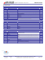
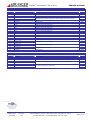
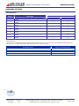
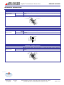
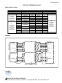
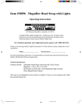
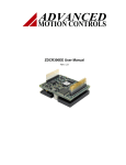
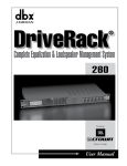
1
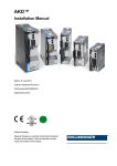
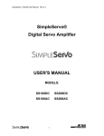
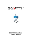
User Manual
BL3410E2-D04-AC120
Plug-n-Play Servo System
with digital drive, brushless motor and cables
(10.5 lb-in, 6000 rpm)
Sold & Serviced By:
Toll Free Phone: 877-378-0240
Toll Free Fax: 877-378-0249
[email protected]
v. 1.02
www.servo2go.com
Thank you for purchasing this QuickStart package!
QuickStart makes it easy to set up Advanced Motion Controls drives to get your system
running quickly. The drive and motor have been matched with each other, the cables are
custom made for this system and an interface board simplifies integration with your
controller.
Remember, if you need us, we are here for you!
Our goal is to get you up and running as quickly as possible. If at any point you have a
question, a team of applications engineers and our customer service staff are just a phone
call away. We are available weekdays from 8am to 5pm Pacific Time at 805-389-1935.
We can also be contacted via email through our website www.a-m-c.com - go to “Contact
Us”.
4 steps to success!
1
Getting Started
What’s included with
QuickStart and what
to expect.
2
5-Minute
QuickStart
Lets spin the motor!
3
Integrate
QuickStart into
your System
Get your machine
working.
4
Going into
Production
Transitioning from
prototype to
production.
This manual has been laid out in four sections to guide you through the process of setting
up and integrating your QuickStart system. By following each step in succession you will
first be introduced to QuickStart, then hook up the system for a simple bench test, and then
integrate QuickStart into your machine and finally transition into the production stage.
Sold & Serviced By:
Toll Free Phone: 877-378-0240
Toll Free Fax: 877-378-0249
[email protected]
www.servo2go.com
2
Advanced Motion Controls · 3805 Calle Tecate, Camarillo, CA 93012
Phone: 805-389-1935 · Fax: 805-389-1165 · www.a-m-c.com
1
Getting Started
BL3410E2-D04-AC120
What to Expect
What is 'QuickStart'?
QuickStart is a system offering including: a drive, a motor, all necessary cables, and an
interface board with screw terminal connections - all in one box ready for fast delivery!
What purpose does 'QuickStart' serve?
QuickStart is intended to introduce OEMs to Advanced Motion Controls servo drives and
provide a positive first experience.
Why is Advanced Motion Controls offering a 'QuickStart' package?
We realize that many OEMs today are faced with trying to get their machinery to market
using the fastest possible methods. Our solution is to provide a means by which motion
control can be quickly proven.
How does 'QuickStart' benefit new users?
QuickStart is designed to make system prototyping easier to include Advanced Motion
Controls' servo drives. The attraction to OEM's is a savings of time, money and the
personnel needed to move from conception to production. Preconfigured wiring means you
can have the motor turning within 5 minutes of opening the box!
Are the motors available for individual resale?
Quite simply, not from Advanced Motion Controls. The motors in these packages are meant
to represent what is commonly available from many different manufacturers. Your local
Advanced Motion Controls representative can handle requests for motor model information
for additional purchases.
How is 'QuickStart' pricing important to me?
Careful selection of systems incorporate popular Advanced Motion Control's servo drives in
order to maximize exposure and minimize costs.
What other considerations should you know about 'QuickStart'?
Although it will be hard to find easy-to-configure systems like these at lower prices
anywhere, QuickStart isn't intended for multiple, pre-packaged system selling. Initial
exposure to Advanced Motion Controls' drives is the key. Each project will be followed up by
our Sales department to determine overall progress and assist in determining the next step.
Sold & Serviced By:
Toll Free Phone: 877-378-0240
Toll Free Fax: 877-378-0249
[email protected]
www.servo2go.com
3
Advanced Motion Controls · 3805 Calle Tecate, Camarillo, CA 93012
Phone: 805-389-1935 · Fax: 805-389-1165 · www.a-m-c.com
1
Getting Started
Package Contents Checklist
Digital Servo Drive
Brushless NEMA 34 Motor w/encoder
Screw Terminal Board
Feedback / Commutation Cable (10 foot)
Motor Power Cable (10 foot)
Drive Cable (1.5 foot)
RS232 Communication Cable
Documentation
Additional Requirements
Item
Power Source
Controller
Windows PC
DPRAHIE-015N400
MBL3410E2
System Interface Board (SIB)
CBL-F02-10
CBL-P05-10
CBL-D03
CBL-RS232
Quick Connect Sheet
User Manual
Brochure with CD ROM
Notes
Requirements:
• 120VAC 60 Hz Single Phase
or
• 208VAC 60 Hz Three Phase
Acceptable Operating Range 40 – 250 VAC
Single Phase or Three Phase
Supported Command Inputs:
• +/-10V command signal
• Step and Direction (24V)
• Encoder Following (electronic gearing)
Computer with serial port to run the DriveWare software
for drive configuration.
Sold & Serviced By:
Toll Free Phone: 877-378-0240
Toll Free Fax: 877-378-0249
[email protected]
www.servo2go.com
4
Advanced Motion Controls · 3805 Calle Tecate, Camarillo, CA 93012
Phone: 805-389-1935 · Fax: 805-389-1165 · www.a-m-c.com
2
5-Minute QuickStart
Let’s spin the motor!
This quick setup procedure will get the motor moving in a short amount of time without the
need for a controller. The drive has been pre-configured for velocity mode with a slight
offset. This will turn the motor at a slow steady speed on power-up to demonstrate
operation. Once the system is shown to be operational, the next section Integrating
QuickStart into your System will guide you through the process of integrating the system
into your application.
Wiring
On page 7 you will find the cables and connections sheet. Use this as a reference when
following the steps in this section.
Drive
Connect either end of cable CBL-D03 to the I/O connector on the drive. Connect the other
end to the C2 connector on the system interface board (SIB).
Feedback
CBL-F02-10 is the feedback cable. Connect the black connectors and shield drain wire on
this cable to the corresponding connectors on the motor. Connect the 15pin D-sub end of
this cable to the Feedback connector on the Drive.
Motor and System Power
Connect the white connector on the motor power cable CBL-P05-10 to the corresponding
connector on the motor. Connect the other end of the cable to the Power connector on the
drive.
Red
Motor Power A
White
Motor Power B
Black
Motor Power C
White AC
Power L1
Black AC
Power L2
The drive is set up to use 120VAC single phase as the power source. Do not apply power at
this time. An AC power strip or other switch can be used to make cycling power more
convenient during testing.
Grounding
Bring all ground wires to a central point ground such as a ground bus, ground plane or a
single ground bolt. Also don't forget to ground the drive chassis! Use the screw marked PE
on the case.
Sold & Serviced By:
Motor Ground – Ground the motor through direct contact with the machine housing or a
short heavy wire from the motor to earth ground. The green wire coming from motor power
cable should only be used if you can’t bring the motor case directly to ground. Don’t ground
the motor at both the green wire and the motor case since this creates a ground loop that
disrupts the feedback signals.
Toll Free Phone: 877-378-0240
Toll Free Fax: 877-378-0249
[email protected]
www.servo2go.com
5
Advanced Motion Controls · 3805 Calle Tecate, Camarillo, CA 93012
Phone: 805-389-1935 · Fax: 805-389-1165 · www.a-m-c.com
2
5-Minute QuickStart
Inhibit Switch (optional for this section)
Digital Input 1 has been assigned as the Inhibit function and this can be used to
inhibit/enable the drive. To do this you will need a switch and a 24V supply.
1. Bring the 24V ground to pin 15 (input common).
2. Tie one terminal of the switch to +24V and the other to pin 11.
With this configuration, opening the switch Enables the drive, closing the switch Disables
the drive.
User Interface and RS232 Cable
The user interface and RS232 Cable should not be hooked up for the 5-Minute QuickStart
procedure.
Cautions
Unexpected motion – To prevent the motor from jumping unexpectedly and causing
damage, the motor should be secured either with clamps or bolted down using its mounting
holes.
Sold & Serviced By:
Toll Free Phone: 877-378-0240
Toll Free Fax: 877-378-0249
[email protected]
www.servo2go.com
6
Advanced Motion Controls · 3805 Calle Tecate, Camarillo, CA 93012
Phone: 805-389-1935 · Fax: 805-389-1165 · www.a-m-c.com
2
5-Minute QuickStart
Sold & Serviced By:
Toll Free Phone: 877-378-0240
Toll Free Fax: 877-378-0249
[email protected]
www.servo2go.com
7
Advanced Motion Controls · 3805 Calle Tecate, Camarillo, CA 93012
Phone: 805-389-1935 · Fax: 805-389-1165 · www.a-m-c.com
2
5-Minute QuickStart
Inhibit Line Test (optional) – Follow this step only if you installed the inhibit switch
described in the wiring section on page 6. This is to verify that the optional inhibit switch is
functioning and the drive is initially powered up in a disabled state.
1. Unplug the motor by disconnecting the white connector on CBL-P05-10. Unplugging
this connection allows you to power up the system without the possibility of spinning
the motor.
2. Apply power to the drive and your 24V supply. Toggle the inhibit switch and verify
that you can cause the LED color to switch between Red and Green. Set the switch
so the LED is Red.
3. Remove power and reconnect the white connector on CBL-P05-10.
System Power Up
1. Apply power to the drive. If an inhibit switch has been installed, enable the drive by
toggling the inhibit switch so the LED turns Green.
2. The motor should turn at a slow speed.
3. If the motor turns then the system has been hooked up correctly. Remove power
and continue to the next section. If not then go to Troubleshooting.
4. To remove the offset from the motor, follow the instructions in Section ‘3b
Configuration’ to connect to the drive and set the offset to 0.
Troubleshooting
LED not lit.
Motor doesn’t have holding torque
LED doesn’t turn Green.
Motor is noisy and vibrates.
Verify that power has been applied to the drive.
Verify that the LED is Green.
Verify all cables are connected.
If an Inhibit Switch has been installed, toggle the
Inhibit switch.
This can happen if there is noise on the feedback
signal. Poor system grounding is the primary cause
for excessive noise.
Verify that the system is properly grounded, then
cycle power.
Contact Factory - If you can’t get the motor turning within a few minutes, please call and
ask for technical support! 805-389-1935. We want to get you up and running quickly!
Sold & Serviced By:
Toll Free Phone: 877-378-0240
Toll Free Fax: 877-378-0249
[email protected]
www.servo2go.com
8
Advanced Motion Controls · 3805 Calle Tecate, Camarillo, CA 93012
Phone: 805-389-1935 · Fax: 805-389-1165 · www.a-m-c.com
3a Wiring
Integrate QuickStart into your System
The following instructions are a continuation of the 5-Minute QuickStart. This section
explains controller wiring, drive configuration, drive mounting, motor mounting, SIB
mounting and load coupling.
Signal Ground
Many of the Inputs and Outputs on this drive are isolated from each other. To control/read
a given input/output the signal and return path must be wired correctly. This manual will
explain how to wire the following signals:
• Analog Reference Input
• 24V Step & Direction Command
• Encoder Following
• Digital Inputs 1 and 2
To wire the other inputs/outputs use the block diagram on the drive datasheet to visualize
the correct wiring.
Command Signal
The command signal and servo drive mode you choose are dictated by the capabilities of
your controller and the desired operation of your system. Analog command signals are
suited for torque and velocity modes, while digital command signals such as Step &
Direction and Encoder Following are associated with Position mode.
+/-10V Command Signal (Single Ended)
Controller
SIB
Available
Drive Modes
Command
C3-4 (Ref+)
C3-2 or C3-16
(SGND)
Torque Mode,
Velocity Mode
Signal Ground
To avoid ground loops there should only be one connection between the drive signal ground and the controller
signal ground. Don’t add a connection if there is already continuity between the two grounds.
+/-10V Command Signal (Differential)
Controller
SIB
Available
Drive Modes
Command +
Command -
C3-4 (Ref+)
C3-5 (Ref-)
C3-2 or C3-16
(SGND)
Torque Mode,
Velocity Mode
Signal Ground
To avoid ground loops there should only be one connection between the drive signal ground and the controller
signal ground. Don’t add a connection if there is already continuity between the two grounds.
Sold & Serviced By:
Toll Free Phone: 877-378-0240
Toll Free Fax: 877-378-0249
[email protected]
www.servo2go.com
9
Advanced Motion Controls · 3805 Calle Tecate, Camarillo, CA 93012
Phone: 805-389-1935 · Fax: 805-389-1165 · www.a-m-c.com
3a Wiring
Integrate QuickStart into your System
24V Step & Direction
Controller
SIB
Available
Drive Mode
Step
Direction
Input Common
C3-17 (+PDI5)
C3-18 (+PDI6)
C3-15
Position Mode
Encoder Following
The Encoder Following command signals are not accessed through the SIB (System
Interface Board). Rather they are accessed directly from the Auxiliary Feedback Connector
labeled “Aux Encoder” on the drive.
Aux Feedback
Available
Controller
Connector on
Drive Mode
Drive
Channel A
Pin 4 (PDI8)
Channel APin 5 (PDI8-)
Position Mode
Channel B
Pin 6 (PDI9)
Channel BPin 7 (PDI9-)
Pin 10, 11 or 12
Signal Ground
(SGND)
For a single ended command signal, leave Channel A- and Channel B- disconnected.
More Information on Mode Selection
Drive modes can be separated into three basic categories: Torque, Velocity and Position.
The name of the mode describes what servo loops are being closed in the drive. They don’t
describe the end-result of the operation. For example, a drive in Torque mode can still be
in a positioning application if the external controller closes the position loop. In fact, most
high performance positioning systems use a drive in torque mode with the controller closing
the velocity and position loops.
The correct mode is determined by the requirements of the controller. Some controllers
require that the drive be in torque mode. Other controllers require that the drive be in
velocity mode. Check the documentation on your controller or contact the manufacturer of
your controller to determine the correct mode for your drive.
Once the command signal and mode have been selected, connect the controller to the
signals as indicated in the above tables. The proper gains and command settings must also
be configured using the DriveWare Software. Software configuration is explained later in
this section.
Sold & Serviced By:
Toll Free Phone: 877-378-0240
Toll Free Fax: 877-378-0249
[email protected]
www.servo2go.com
10
Advanced Motion Controls · 3805 Calle Tecate, Camarillo, CA 93012
Phone: 805-389-1935 · Fax: 805-389-1165 · www.a-m-c.com
3a Wiring
Integrate QuickStart into your System
Drive Inhibit (recommended)
The inhibit line is used to turn off power to the motor while the drive is still powered on.
Sometimes this is necessary if power to the motor needs to be removed quickly or if the
user needs to manually move the load in a freewheeling condition. If your controller has an
inhibit function then we highly recommend that you use it.
Inhibit Connection
Controller
Inhibit
Input Common
SIB
C3-11 (PDI1)
C3-15
Note: The inhibit input is configured to disable the drive when pulled low (active low). The
control logic can be inverted by setting it to active high in the DriveWare software.
Feedback
The feedback on the motor is an incremental encoder with two Channels (A and B) and an
Index (I). The signals are differential but are compatible with single ended circuitry (simply
leave the complimentary signals open A-, B- and I-). The resolution is 10000 counts per
revolution (quadrature).
Power Requirements - Encoder power is supplied by the drive. 5VDC @ 125mA.
The screw terminals on the System Interface Board (SIB) provide easy access to the
encoder signals.
Encoder connection to your controller
Signal
Channel A+
Channel AChannel B+
Channel BChannel I+
Channel I-
SIB
C3-20
C3-21
C3-22
C3-23
C3-24
C3-25
To properly detect the encoder signals, the Signal Grounds on the servo drive and controller need to be connected.
Sold & Serviced By:
Toll Free Phone: 877-378-0240
Toll Free Fax: 877-378-0249
[email protected]
www.servo2go.com
11
Advanced Motion Controls · 3805 Calle Tecate, Camarillo, CA 93012
Phone: 805-389-1935 · Fax: 805-389-1165 · www.a-m-c.com
3a Wiring
Integrate QuickStart into your System
Drive Mounting
Mounting Dimensions can be found in the drive datasheet in the Appendix.
The drive can be mounted flat against the base plate or along the spine.
Mounting the drive flat on the base plate against a large thermally conductive surface for
cooling will provide the most natural heat dissipation for the drive. A metal back plane in a
cabinet on the machine often makes a good surface.
Drives mounted on the spine can be mounted next to each other. Maintain a minimum
separation of 1 inch between drives to provide adequate convection cooling.
Note: Additional cooling may be necessary to dissipate the heat generated by the drive
depending on the ambient temperature, duty cycle and natural ventilation.
Motor Mounting
Mounting Dimensions can be found in the motor datasheet in the Appendix.
The mounting surface must be stiff enough so it does not deflect when radial loads are
applied to the motor shaft. The mounting surface should also have good thermal
conductivity, especially if peak performance is demanded of the motor.
SIB Mounting
Mounting Dimensions can be found in the SIB datasheet in the Appendix.
The SIB can be mounted using the mounting holes or a DIN tray such as from Phoenix
Contact. If using the mounting holes, standoffs must be used to keep the bottom of the SIB
from shorting with the mounting surface.
Cable Routing
Cable Datasheets can be found in the Appendix.
QuickStart cables come with excellent shielding and make proper grounding easy. This
makes proper cable routing less critical, however proper routing practices should still be
followed.
Route cables to minimize length and minimize exposure to noise sources. The motor power
wires are a major source of noise and the motor feedback wires are susceptible to receiving
noise. This is why it is never a good practice to route the motor power wires close to the
motor feedback wires even if they are shielded. Although both of these cables originate at
Sold & Serviced By:
the amplifier and terminate at the motor, try to find separate paths that maintain distance
between the two. A rule of thumb for the minimum distance between these wires is 1cm for
Toll Free Phone: 877-378-0240
Toll Free every
Fax: 877-378-0249
1m of cable length.
[email protected]
www.servo2go.com
12
Advanced Motion Controls · 3805 Calle Tecate, Camarillo, CA 93012
Phone: 805-389-1935 · Fax: 805-389-1165 · www.a-m-c.com
3a Wiring
Integrate QuickStart into your System
Grounding
Bring all ground wires to a central point ground such as a ground bus, ground plane or a
single ground bolt. Also don't forget to ground the drive chassis! Use the silver screw
marked PE on the case.
Motor Ground – The green wire coming from motor power cable is the motor chassis
ground. If the motor case is already grounded through direct contact with the machine
housing, then leave the green wire disconnected. Grounding the motor at both the green
wire and at the motor case causes a ground loop that has been shown to disrupt the
feedback signals. Choose one or the other.
Grounding the motor case directly rather than through the green grounding wire results in
better noise reduction.
Load Coupling
A non-rigid coupling must be used between the motor shaft and the load to minimize
mechanical stress due to radial loads, axial loads or misalignment. If you feel that the
radial load on the motor is excessive, you may want to consider connecting the motor to an
idler shaft that is supported by pillow block bearings (or similar). Then the load can be
coupled to the idler shaft without risking damage to the motor bearings.
Sold & Serviced By:
Toll Free Phone: 877-378-0240
Toll Free Fax: 877-378-0249
[email protected]
www.servo2go.com
13
Advanced Motion Controls · 3805 Calle Tecate, Camarillo, CA 93012
Phone: 805-389-1935 · Fax: 805-389-1165 · www.a-m-c.com
3b Configuration
Integrate QuickStart into your System
Configuration / Software
Advanced Motion Controls DP Series DigiFlex® Servo Drives are configured using the
DriveWare configuration software. DriveWare can be found on the CD ROM that came with
your QuickStart package or it can be downloaded from the Advanced Motion Controls
website at
http://www.a-m-c.com/content/support/categories/dprs232.html.
The basic setup of DigiFlex® servo drives is designed to be user friendly. These instructions
will walk you through the steps necessary to configure your drive to your system:
Connect to the drive
Configure the drive mode.
• Torque
• Velocity
Set Velocity Limits
• Position
Set Position Limits
Save your project often to the DriveWare\My Projects directory.
For topics not covered in this guide, assistance is available through any of the following:
• DriveWare Help files
• www.a-m-c.com
• Technical Assistance via phone: 805-389-1935
Technical Assistance via e-mail: [email protected].
Note: Complete software documentation can be found on the Advanced Motion
Controls website under ‘Support/DigiFlex Performance Series – RS232/RS485’.
Sold & Serviced By:
Toll Free Phone: 877-378-0240
Toll Free Fax: 877-378-0249
[email protected]
www.servo2go.com
14
Advanced Motion Controls · 3805 Calle Tecate, Camarillo, CA 93012
Phone: 805-389-1935 · Fax: 805-389-1165 · www.a-m-c.com
3b Configuration
Integrate QuickStart into your System
Connect to the Drive
1. Install the AMC DriveWare software onto your PC. Follow instructions to assure
complete installation.
2. Connect an available RS-232 communications port on your PC to the serial interface on
the drive. Use the cable provided with your QuickStart system.
3. If desired, connect the Inhibit/Enable circuit as described in the QuickStart User Manual.
4. Apply power to the drive.
5. Launch DriveWare to start the setup software.
6. At the opening screen, select Connect to a drive and click “OK”.
7. Use the default settings (COM1, 9600),
Note: If this doesn’t work, select Auto Detect, then Start Scan…. Once the drive is found
select Apply Settings then Connect.
Sold & Serviced By:
Note: You are now connected to the drive. The status indicator on the bottom right corner
of the screen should indicate “CONNECTED.”
Toll Free Phone: 877-378-0240
Toll Free Fax: 877-378-0249
[email protected]
www.servo2go.com
15
Advanced Motion Controls · 3805 Calle Tecate, Camarillo, CA 93012
Phone: 805-389-1935 · Fax: 805-389-1165 · www.a-m-c.com
3b Configuration
Integrate QuickStart into your System
8. For the best performance when running network intensive applications such as the real
time oscilloscope, you should increase to the highest baud rate available for your
system. To change the RS-232 communications baud rate, you must first be connected
to the drive, then follow these steps:
a. On the Menu bar, select Communication
Connect (or click the Connection
)
Settings icon
b. Select the new baud rate.
c. Click OK to set the new baud rate.
d. To save the settings in the drive select Drive
Store to drive (or click the Store
), then OK to store parameters to the drive nonvolatile memory.
Settings icon
Note: Some PC’s may not communicate reliably at higher baud rates. If increasing the
communications baud rate results in communications errors, use a lower rate.
The Block Diagram window gives access to the servo drives’ setup parameters.
Sold & Serviced By:
Toll Free Phone: 877-378-0240
Toll Free Fax: 877-378-0249
[email protected]
www.servo2go.com
16
Advanced Motion Controls · 3805 Calle Tecate, Camarillo, CA 93012
Phone: 805-389-1935 · Fax: 805-389-1165 · www.a-m-c.com
3b Configuration
Integrate QuickStart into your System
Drive Mode Configuration
The drive has been configured with an offset to make the motor turn without a command.
Before you configure the drive, remove the offset so the motor doesn’t keep turning.
In the Block Diagram, select the Command block.
1. Select No Command
2. Click OK on the Command Source window.
Note: No Command is a non-operation input source that prevents sudden motion. If the
drive is in velocity or current mode, No Command will always provide a command of zero.
If the drive is in position mode, No Command sets Position Target equal to the Position
Measured.
Enable/Disable
The drive can be enabled and disabled by clicking the Enable/Disable icon in the toolbar
If you are using an external inhibit switch, the
icon cannot override it. In this case to
enable, both the switch AND the Enable/Disable icon need to be set to Enable .
.
You are now ready to configure the drive for your system:
Torque Mode
Page 18
Sold & Serviced By:
Toll Free Phone: 877-378-0240
Toll Free Fax: 877-378-0249
[email protected]
www.servo2go.com
Velocity Mode
Page 22
Position Mode
The Velocity loop must be
tuned first, Page 22.
Then the drive can be set
in Position Mode, Page
30.
17
Advanced Motion Controls · 3805 Calle Tecate, Camarillo, CA 93012
Phone: 805-389-1935 · Fax: 805-389-1165 · www.a-m-c.com
3b Configuration (Torque Mode)
Integrate QuickStart into your System
Torque Mode
Your QuickStart drive has been configured in Velocity mode. To change to torque mode
simply disable the Velocity loop.
1.
In the block diagram, click on the Velocity Loop block.
Sold & Serviced By:
Toll Free Phone: 877-378-0240
Toll Free Fax: 877-378-0249
[email protected]
www.servo2go.com
18
Advanced Motion Controls · 3805 Calle Tecate, Camarillo, CA 93012
Phone: 805-389-1935 · Fax: 805-389-1165 · www.a-m-c.com
3b Configuration (Torque Mode)
Integrate QuickStart into your System
2.
This opens the Velocity Loop screen. To disable the velocity loop, uncheck the box
that says “Velocity Loop Enabled”. Click OK.
Sold & Serviced By:
Toll Free Phone: 877-378-0240
Toll Free Fax: 877-378-0249
[email protected]
www.servo2go.com
19
Advanced Motion Controls · 3805 Calle Tecate, Camarillo, CA 93012
Phone: 805-389-1935 · Fax: 805-389-1165 · www.a-m-c.com
3b Configuration (Torque Mode)
Integrate QuickStart into your System
Notice that the symbols in the Velocity Block have changed. The feedback arrows no longer
extend into the block and the “1” indicates that the velocity loop is disabled and is set to
unity gain.
Command Source Selection for Torque Mode
In the Block Diagram window, select the Command Source block.
1. Select Analog Input 1
2. Click OK.
Note: No Command is a non-operation input source that prevents sudden motion. If the
Toll Free Phone: 877-378-0240
is in velocity or current mode, No Command will always provide a command of zero.
Toll Free drive
Fax: 877-378-0249
[email protected]
If
the
drive is in position mode, No Command sets Position Target equal to the Position
www.servo2go.com
Measured.
20
Sold & Serviced By:
Advanced Motion Controls · 3805 Calle Tecate, Camarillo, CA 93012
Phone: 805-389-1935 · Fax: 805-389-1165 · www.a-m-c.com
3b Configuration (Torque Mode)
Integrate QuickStart into your System
Analog Input Scaling
1. Set the analog command scaling as follows:
a. In the Block Diagram window, select Inputs/Outputs.
b. Set the desired scaling (e.g. Amps/Volt) for Analog Input 1.
The Polarity of the signal can be changed by setting the scaling value to a
negative number. The offset voltage and deadband can also be set from this
screen.
c. Click Apply or OK to set any modified values.
), then
2. On the Menu Bar, select Drive
Store to drive (or click the Store Settings icon
OK to store parameters to the drive nonvolatile memory.
3. The Analog Input may now be used to apply a current command to the drive.
Sold & Serviced By:
Further assistance is available through any of the following:
• DriveWare Help files
• www.a-m-c.com
Toll Free Phone: 877-378-0240
• Technical Assistance via phone: 805-389-1935
Toll Free Fax: 877-378-0249
[email protected]
• Technical Assistance via e-mail: [email protected].
www.servo2go.com
21
Advanced Motion Controls · 3805 Calle Tecate, Camarillo, CA 93012
Phone: 805-389-1935 · Fax: 805-389-1165 · www.a-m-c.com
3b Configuration (Velocity Mode)
Integrate QuickStart into your System
Velocity Mode
Your QuickStart drive is already in Velocity Mode, however the velocity loop has been tuned
for the unloaded motor.
Velocity Loop tuning is dependent on the system mechanics and inertia, therefore for best
performance; the Velocity Loop must be tuned with the motor installed in the system and
coupled to the load.
Velocity Loop Tuning
1. Verify that the drive is disabled ( ).
2. From the Main Block Diagram, select the Velocity Loop block.
3. In the Velocity Loop window, click the Limits button to open the Velocity Limits tab in
Limits & Options.
Sold & Serviced By:
Toll Free Phone: 877-378-0240
Toll Free Fax: 877-378-0249
[email protected]
www.servo2go.com
22
Advanced Motion Controls · 3805 Calle Tecate, Camarillo, CA 93012
Phone: 805-389-1935 · Fax: 805-389-1165 · www.a-m-c.com
3b Configuration (Velocity Mode)
Integrate QuickStart into your System
4. The limits have been preset to the maximum capabilities of the motor/servo drive
system. If you wish, lower values can be set to match your machine requirements. Set
values for At Velocity Window, Velocity Following Error, Positive Velocity Limit, and
Negative Velocity Limit.
Note: Velocity limit values cannot exceed the Maximum Speed rating of the motor (from
the Motor Data window).
5. Click “OK” to accept values and close Limits & Options.
6. Open the Waveform Generator by clicking the Waveform Generator button.
Sold & Serviced By:
Toll Free Phone: 877-378-0240
Toll Free Fax: 877-378-0249
[email protected]
www.servo2go.com
23
Advanced Motion Controls · 3805 Calle Tecate, Camarillo, CA 93012
Phone: 805-389-1935 · Fax: 805-389-1165 · www.a-m-c.com
3b Configuration (Velocity Mode)
Integrate QuickStart into your System
7. With the Waveform Generator, establish a Square wave into the Velocity Loop with an
amplitude of approximately 10% of the expected motor speed during system operation.
Set the Frequency low enough so the motor has enough time to reach the commanded
velocity, but high enough to prevent the system from reaching any mechanical limits on
the machine (e.g.: 1-3Hz).
Note: The accuracy of velocity loop tuning is dependent on the quality and resolution of
the velocity feedback. Sources with relatively low resolution or higher noise will require
tuning at a higher velocity in order to overcome the effects of these limitations. It is
best to experimentally determine the optimum tuning setup.
8. To open the digital oscilloscope, select Tools
Oscilloscope (or click the Oscilloscope
.) Use the help files in the DriveWare software for detailed instructions on how to
icon
use the oscilloscope. In the menu bar go to Help
AMC DriveWare Help
Help
Help
Index
Use the digital scope.
Set up the oscilloscope as follows:
a. Set Motor Velocity Target to channel 1 and the Motor Velocity Measured to
channel 2.
b. Set the Trigger Source to Motor Velocity Target at a level of zero RPM, Up Slope.
Sold & Serviced By:
Toll Free Phone: 877-378-0240
Toll Free Fax: 877-378-0249
[email protected]
www.servo2go.com
24
Advanced Motion Controls · 3805 Calle Tecate, Camarillo, CA 93012
Phone: 805-389-1935 · Fax: 805-389-1165 · www.a-m-c.com
3b Configuration (Velocity Mode)
Integrate QuickStart into your System
9. To keep the signal from jumping around, set the Trigger Mode to Normal.
10. Enable the drive by clicking the Enable/Disable Drive icon
.
Sold & Serviced By:
Toll Free Phone: 877-378-0240
Toll Free Fax: 877-378-0249
[email protected]
www.servo2go.com
25
Advanced Motion Controls · 3805 Calle Tecate, Camarillo, CA 93012
Phone: 805-389-1935 · Fax: 805-389-1165 · www.a-m-c.com
3b Configuration (Velocity Mode)
Integrate QuickStart into your System
11. The desktop should be arranged so the oscilloscope is visible while adjusting the tuning
values and waveform generator. Results vary depending on screen resolution.
12. Use the Proportional Gain and Integral Gain sliders or arrow buttons to adjust the Motor
Velocity Measured waveform on the oscilloscope and match the Motor Velocity Target as
closely as possible. The Feedback Filter Cut Off Frequency can be used to smooth the
response.
and
13. When tuning is complete, disable the drive with the Enable/Disable Drive icon
select Not Connected on the Waveform Generator.
),
14. On the Menu Bar, select Drive
Store to Drive (or click the Store Settings icon
then OK to store parameters to the drive nonvolatile memory.
***Note the Velocity Loop is now sufficiently tuned. For Position Mode
applications proceed to Position Mode configuration page 30.
For Velocity Mode applications continue onto the next page to configure the
command source.
Sold & Serviced By:
Toll Free Phone: 877-378-0240
Toll Free Fax: 877-378-0249
[email protected]
www.servo2go.com
26
Advanced Motion Controls · 3805 Calle Tecate, Camarillo, CA 93012
Phone: 805-389-1935 · Fax: 805-389-1165 · www.a-m-c.com
3b Configuration (Velocity Mode)
Integrate QuickStart into your System
Velocity Loop Command Profiling (Optional)
The command profiler can be used to limit the acceleration and deceleration from step input
commands. The command profiler provides independent control of acceleration and
deceleration in both the positive and negative velocity directions.
1. From the Main Block Diagram, open the Command block.
2. Activate the check box for Command Profiler Enabled.
3. Using the slider bars or numerical entry, enter the desired acceleration values.
Independent values can be entered for both acceleration and deceleration in both the
positive and negative directions. Click OK when done.
Sold & Serviced By:
Toll Free Phone: 877-378-0240
Toll Free Fax: 877-378-0249
[email protected]
www.servo2go.com
27
Advanced Motion Controls · 3805 Calle Tecate, Camarillo, CA 93012
Phone: 805-389-1935 · Fax: 805-389-1165 · www.a-m-c.com
3b Configuration (Velocity Mode)
Integrate QuickStart into your System
Command Source Selection
1. In the Block Diagram window, select the Command block.
2. Select Analog Input 1. Click OK to accept the selection and close the window.
Note: No Command is designed to be a non-operation input source. If the drive is in
velocity or current mode, No Command will always provide a command of zero.
Sold & Serviced By:
Toll Free Phone: 877-378-0240
Toll Free Fax: 877-378-0249
[email protected]
www.servo2go.com
28
Advanced Motion Controls · 3805 Calle Tecate, Camarillo, CA 93012
Phone: 805-389-1935 · Fax: 805-389-1165 · www.a-m-c.com
3b Configuration (Velocity Mode)
Integrate QuickStart into your System
Analog Input Scaling
1. Set the analog command scaling as follows:
a. In the Block Diagram window, select the Inputs/Outputs block.
b. For the appropriate Analog Input, (as previously selected,) set the required
scaling (e.g. RPM/Volt). If desired, an offset or deadband can also be applied
from this screen.
c. Command polarity can be inverted by changing the sign (+/-) on the Analog
Input scaling.
d. Click Apply or OK to set any modified values.
e. On the Menu Bar, select Drive
Store to drive (or click the Store Settings icon
), then OK to store parameters to the servo drive.
2. The Analog Input is now configured and can be used to apply a velocity command to the
drive.
Further assistance is available through any of the following:
• DriveWare Help files
• www.a-m-c.com
• Technical Assistance via phone: 805-389-1935
• Technical Assistance via e-mail: [email protected].
Sold & Serviced By:
Toll Free Phone: 877-378-0240
Toll Free Fax: 877-378-0249
[email protected]
www.servo2go.com
29
Advanced Motion Controls · 3805 Calle Tecate, Camarillo, CA 93012
Phone: 805-389-1935 · Fax: 805-389-1165 · www.a-m-c.com
3b Configuration (Position Mode)
Integrate QuickStart into your System
Position Mode
Before the servo drive can be configured in Position Mode, the Velocity Loop must be tuned
to match the system. Follow the instructions for Velocity Mode configuration first.
Position Loop tuning is dependent on the system mechanics and inertia, therefore for best
performance; the Position Loop must be tuned with the motor installed in the system and
coupled to the load.
1. Verify that the drive is disabled ( ).
2. From the Main Block Diagram, open the Position Loop window.
Sold & Serviced By:
Toll Free Phone: 877-378-0240
Toll Free Fax: 877-378-0249
[email protected]
www.servo2go.com
30
Advanced Motion Controls · 3805 Calle Tecate, Camarillo, CA 93012
Phone: 805-389-1935 · Fax: 805-389-1165 · www.a-m-c.com
3b Configuration (Position Mode)
Integrate QuickStart into your System
3. Select the check box for Position Loop Enabled.
4. In the Position Loop window, click the Limits button to open the Position Limits tab in the
Limits & Options window.
5. Enter values for In Position Window and Position Following Error Window. To prevent
the drive from unintentionally disabling, the Position Following Error Window has been
preconfigured to a large value equivalent to two motor revolutions. The value can be
reduced to meet your system requirements, but if it is set too small, you may have
difficulty enabling the drive if the motor is out of position.
Sold & Serviced By:
Toll Free Phone: 877-378-0240
Toll Free Fax: 877-378-0249
[email protected]
www.servo2go.com
31
Advanced Motion Controls · 3805 Calle Tecate, Camarillo, CA 93012
Phone: 805-389-1935 · Fax: 805-389-1165 · www.a-m-c.com
3b Configuration (Position Mode)
Integrate QuickStart into your System
6. If appropriate for your machine, enter values for the Max and Min Target Position Limit,
or leave the limits disabled.
7. Set the Measured Position Value to zero (0) counts.
8. Click “OK” to accept values and close Limits & Options.
Sold & Serviced By:
Toll Free Phone: 877-378-0240
Toll Free Fax: 877-378-0249
[email protected]
www.servo2go.com
32
Advanced Motion Controls · 3805 Calle Tecate, Camarillo, CA 93012
Phone: 805-389-1935 · Fax: 805-389-1165 · www.a-m-c.com
3b Configuration (Position Mode)
Integrate QuickStart into your System
Note: The drive has been configured to disable due to a following error if the
Measured Position doesn’t match the Target Position. A large following error is
likely if you have been running the motor in Velocity mode and then switched to
Position mode. For your convenience, Digital Input 2 (pin 12 on the SIB) has been
configured to set the Measured Position equal to 0. To set the Measured Position
to zero, briefly pull Digital Input 2 to signal ground. A switch or push button can
be wired here for convenience.
9. Open the Waveform Generator.
10. With the drive still disabled, use the Waveform Generator to establish a Square wave
into the Position Loop with amplitude of 1000 to 1500 counts. The frequency should be
slow enough to allow the motor to settle into position (e.g. 1-2Hz). Decimal values for
the frequency can be set for very heavy machines.
If the waveform generator shows a large offset, use Digital Input 2 to set the measured
position to 0 (briefly pull pin 12 to pin 2 on the SIB). Then click the “Set To Measured
Position” button. The offset should now read “0”.
Continued…
Sold & Serviced By:
Toll Free Phone: 877-378-0240
Toll Free Fax: 877-378-0249
[email protected]
www.servo2go.com
33
Advanced Motion Controls · 3805 Calle Tecate, Camarillo, CA 93012
Phone: 805-389-1935 · Fax: 805-389-1165 · www.a-m-c.com
3b Configuration (Position Mode)
Integrate QuickStart into your System
11. Open the oscilloscope
and set it up as follows:
a. Set Channel 1 to Motor Position Target and Channel 2 to Motor Position
Measured. Set the scaling on these channels to 500 counts/div.
b. In the Trigger area of the scope, use the Change button to set Motor Position
Target as the Trigger Source at a level of zero Counts, Up Slope.
12. Set the Trigger Mode to Normal. Change the Time/Div to 20msec.
13. Enable the drive by clicking the Enable/Disable Drive icon
.
14. Use the Proportional Gain and Integral Gain sliders to adjust the Position Measured
waveform on the oscilloscope to achieve the desired response. Use the arrow buttons
for fine-tuning. Take care not to ‘over-tune’ the system. This can result in excessive
vibration and audible noise.
Sold & Serviced By:
15. When tuning is complete, disable the drive
and select Not Connected on the
Waveform Generator. Close the Waveform Generator, Oscilloscope and Position Loop
Toll Free Phone: 877-378-0240
screen.
Toll Free Fax: 877-378-0249
[email protected]
), then
16. On the Menu Bar, select Drive
Store to drive (or click the Store Settings icon
www.servo2go.com
OK to store parameters to the drive nonvolatile memory.
34
Advanced Motion Controls · 3805 Calle Tecate, Camarillo, CA 93012
Phone: 805-389-1935 · Fax: 805-389-1165 · www.a-m-c.com
3b Configuration (Position Mode)
Integrate QuickStart into your System
Command Source Selection
1. In the Block Diagram window, select the Command block.
2. Select the command source appropriate for your system. Step and Direction and
Encoder Following are the easiest to set up for position mode.
, set the step and
3. Accesses additional parameters by clicking the ellipsis button
direction or encoder following scaling.
4. Click OK on the Command Source window.
Note: No Command is designed to be a non-operation input source. If the drive is in
velocity or current mode, No Command will always provide a command of zero. If the
drive is in position mode, when the command is set to No Command the drive sets Position
Target equal to the Position Measured to prevent sudden motion.
Further assistance is available through any of the following:
•
•
•
•
DriveWare Help files
www.a-m-c.com
Technical Assistance via phone: 805-389-1935
Technical Assistance via e-mail: [email protected].
Sold & Serviced By:
Toll Free Phone: 877-378-0240
Toll Free Fax: 877-378-0249
[email protected]
www.servo2go.com
35
Advanced Motion Controls · 3805 Calle Tecate, Camarillo, CA 93012
Phone: 805-389-1935 · Fax: 805-389-1165 · www.a-m-c.com
4
Going into Production
Prototype to Production
Once you have completed your proof of concept you will be ready to design for production.
If you decide that the QuickStart drive and motor are perfect for you then you’re in luck.
Both are popular off-the-shelf items that are readily available. Drives can be ordered
directly from us and we can put you in touch with the appropriate motor supplier.
If your servo system requires a drive that better fits your application such as:
• Additional features
• Different power range
• Smaller size
• Different form factor such as ‘plug in’ style drives
• Network connectivity
Then an ADVANCED Motion Controls applications engineer can help optimize your system by
selecting the best drive for your needs.
Our local representatives can also help you with the selection of motors and other system
components such as cables, gear boxes, slides, bearings and more.
Feedback
Your feedback is important to us. Your comments can make QuickStart better and help us
improve our processes, technical support, customer support and product offering. Please go
to www.a-m-c.com and select Contact Us.
Sold & Serviced By:
Toll Free Phone: 877-378-0240
Toll Free Fax: 877-378-0249
[email protected]
www.servo2go.com
36
Advanced Motion Controls · 3805 Calle Tecate, Camarillo, CA 93012
Phone: 805-389-1935 · Fax: 805-389-1165 · www.a-m-c.com
5
Appendix
A. System Specifications
B. Drive
C. Motor
D. Cables
E. System Interface Board
Sold & Serviced By:
Toll Free Phone: 877-378-0240
Toll Free Fax: 877-378-0249
[email protected]
www.servo2go.com
37
Advanced Motion Controls · 3805 Calle Tecate, Camarillo, CA 93012
Phone: 805-389-1935 · Fax: 805-389-1165 · www.a-m-c.com
Sold & Serviced By:
Toll Free Phone: 877-378-0240
Toll Free Fax: 877-378-0249
[email protected]
www.servo2go.com
System Specifications
Torque – peak
Torque – continuous
Velocity Maximum
Supply Voltage
Encoder Resolution
21.1 lb-in, 2.38 Nm
10.57 lb-in, 1.19 Nm
6000 rpm
120VAC
10000 counts / rev
Speed Torque Curve
Sold & Serviced By:
Toll Free Phone: 877-378-0240
Toll Free Fax: 877-378-0249
[email protected]
www.servo2go.com
Advanced Motion Controls · 3805 Calle Tecate, Camarillo, CA 93012
Phone: 805-389-1935 · Fax: 805-389-1165 · www.a-m-c.com
Sold & Serviced By:
Toll Free Phone: 877-378-0240
Toll Free Fax: 877-378-0249
[email protected]
www.servo2go.com
DigiFlex® Performance™ Servo Drive
Description
DPRAHIE-015N400
Power Range
The DigiFlex® Performance™ (DP) Series digital servo
drives are designed to drive brushed and brushless
servomotors. These fully digital drives operate in
torque, velocity, or position mode and employ Space
Vector Modulation (SVM), which results in higher bus
voltage utilization and reduced heat dissipation
compared to traditional PWM. The command source
can be generated internally or can be supplied
externally. In addition to motor control, these drives
feature dedicated and programmable digital and
analog inputs and outputs to enhance interfacing with
external controllers and devices.
Peak Current
15 A (10.6 ARMS)
Continuous Current
7.5 A (5.3 ARMS)
Supply Voltage
90 - 264 VAC
This DP Series drive features a single RS-232/RS-485
interface used for drive configuration and setup. Drive
commissioning is accomplished using DriveWare,
available at www.a-m-c.com.
All drive and motor parameters are stored in nonvolatile memory.
Features
Four quadrant regenerative operation
PIDF velocity loop
Space vector modulation (SVM) technology
PID + FF position loop
Fully digital state-of-the-art design
Compact size, high power density
Programmable gain settings
16-bit analog to digital hardware
Fully configurable current, voltage, velocity and
position limits
MODES OF OPERATION
Current
Position
Velocity
INPUTS/OUTPUTS
3 High Speed Captures
4 Programmable Analog Inputs (16-bit/12-bit
Resolution)
3 Programmable Digital Inputs (Differential)
7 Programmable Digital Inputs (Single-Ended)
4 Programmable Digital Outputs (Single-Ended)
COMMAND SOURCE
Encoder Following
±10 V Analog
24 V Step & Direction
FEEDBACK SUPPORTED
Halls
Incremental Encoder
±10 V Analog
Auxiliary Incremental Encoder
COMPLIANCES & AGENCY APPROVALS
RoHS
UL/cUL Pending
CE Pending
Sold & Serviced By:
Toll Free Phone: 877-378-0240
Toll Free Fax: 877-378-0249
[email protected]
www.servo2go.com
Release Date:
3/11/2008
Revision:
1.04
Advanced Motion Controls · 3805 Calle Tecate, Camarillo, CA, 93012
ph# 805-389-1935 · fx# 805-389-1165· www.a-m-c.com
Page 1 of 10
DigiFlex® Performance™ Servo Drive
DPRAHIE-015N400
BLOCK DIAGRAM
CONTROL MODULE
+5V
PDI-1,2,3,4,5,6,7
(STEP / DIR / CAP-1)
3.75K
10k
HALL A,B,C +
INPUT COMMON
PDI-8,9,10 + (AUX ENC
A,B + / CAP-2,3)
+5V
5k
Drive
Logic
+5V
10k
PDI-8,9,10 – (AUX
ENC A,B –)
10k
OUTPUT PULL-UP
PDO-1,2,3,4
20k
20k
20k
+5V
HALL A,B,C –
5k
+5V
MOT ENC A,B,I +
10k
MOT ENC A,B,I –
10k
ENC A,B,I + OUT
ENC A,B,I – OUT
I/O Interface
OUTPUT COMMON
PAI-1,4 – (REF–)
20k
I/O Interface
5k
PAI-1,4 + (REF+)
Motor Feedback
Motor Feedback
+5V
POWER MODULE
20k
MOTOR A
PAI-2,3
Power Stage
PAI-2: 33k
PAI-3: 500k
MOTOR B
MOTOR C
SGN GND
L1
L2
L3
SELECT
DC+
TX/TX–
RX/RX–
TX+
RX+
DC-
RS232/485
Interface
Logic Power
ISO GND
Approvals and Compliances
US and Canadian safety compliance with UL 508c, the industrial standard for power conversion electronics. UL
registered under file number E140173. Note that machine components compliant with UL are considered UL
registered as opposed to UL listed as would be the case for commercial products.
Compliant with European CE for both the Class A EMC Directive 89/336/EEC on Electromagnetic Compatibility
(specifically EN 61000-6-4:2001, EN 61000-6-2:2001, EN 61000-3-2:2000, and EN 61000-3-3:1995/A1:2001) and
LVD requirements of directive 73/23/EEC (specifically EN 60204-1), a low voltage directive to protect users from
electrical shock.
RoHS (Reduction of Hazardous Substances) is intended to prevent hazardous substances such as lead from being
manufactured in electrical and electronic equipment.
Sold & Serviced By:
Toll Free Phone: 877-378-0240
Toll Free Fax: 877-378-0249
[email protected]
www.servo2go.com
Release Date:
3/11/2008
Revision:
1.04
Advanced Motion Controls · 3805 Calle Tecate, Camarillo, CA, 93012
ph# 805-389-1935 · fx# 805-389-1165· www.a-m-c.com
Page 2 of 10
DigiFlex® Performance™ Servo Drive
DPRAHIE-015N400
SPECIFICATIONS
Power Specifications
Description
Units
AC Supply Voltage Range
Nominal AC Supply Voltage
Rated Supply Voltage
AC Input Phases1
AC Supply Frequency
DC Supply Voltage Range
DC Bus Over Voltage Limit
DC Bus Under Voltage Limit
Maximum Peak Output Current
Maximum Continuous Output Current
Max. Continuous AC Current Draw @ Rated Voltage
Max. Continuous Output Power @ Rated Voltage
Max. Continuous Power Dissipation @ Rated Voltage
Internal Bus Capacitance
Minimum Load Inductance (Line-To-Line)2
Switching Frequency
Low Voltage Supply Outputs
VAC
VAC
VAC
Hz
VDC
VDC
VDC
A (Arms)
A (Arms)
A
W
W
µF
µH
kHz
-
Value
90 - 264
120 - 240
240
3
50 - 60
127 - 373
393.8
55
15 (10.6)
7.5 (5.3)
4.3
1710
90
660
600
20
+5 VDC (250 mA)
Control Specifications
Description
Units
Value
Communication Interfaces
Command Sources
Feedback Supported
Commutation Methods
Modes of Operation
Motors Supported
-
Hardware Protection
-
RS-232, RS-485
24 V Step & Direction, ±10 V Analog, Encoder Following
±10 V Analog, Auxiliary Incremental Encoder, Halls, Incremental Encoder
Sinusoidal, Trapezoidal
Current, Position, Velocity
Brushed, Brushless, Induction, Voice Coil
40+ Configurable Functions, Over Current, Over Temperature (Drive & Motor), Over
Voltage, Short Circuit (Phase-Phase & Phase-Ground), Under Voltage
10/4
4/0
50
100
100
20 (5 pre-quadrature)
Programmable Digital Inputs/Outputs (PDIs/PDOs)
Programmable Analog Inputs/Outputs (PAIs/PAOs)
Current Loop Sample Time
Velocity Loop Sample Time
Position Loop Sample Time
Maximum Encoder Frequency
μs
μs
μs
MHz
Mechanical Specifications
Description
Agency Approvals
Size (H x W x L)
Weight
Heatsink (Base) Temperature Range3
Storage Temperature Range
Cooling System
Form Factor
IP Rating
AUX ENCODER Connector
COMM Connector
FEEDBACK Connector
I/O Connector
P1 Connector
Units
mm (in)
g (oz)
°C (°F)
°C (°F)
-
Value
CE Pending, RoHS, UL/cUL Pending
177.5 x 139.7 x 55.9 (7 x 5.5 x 2.2)
1264 (44.6)
0 - 65 (32 - 149)
-40 - 85 (-40 - 185)
Natural Convection
Stand Alone
IP10
15-pin, high-density, male D-sub
9-pin, female D-sub
15-pin, high-density, female D-sub
26-pin, high-density, female D-sub
8-port, 7.62 mm spaced, enclosed, friction lock header
Notes
1.
2.
3.
Can operate on single-phase 120/240 VAC if peak/cont. current ratings are reduced by at least 30%.
Lower inductance is acceptable for bus voltages well below maximum. Use external inductance to meet requirements.
Additional cooling and/or heatsink may be required to achieve rated performance.
Sold & Serviced By:
Toll Free Phone: 877-378-0240
Toll Free Fax: 877-378-0249
[email protected]
www.servo2go.com
Release Date:
3/11/2008
Revision:
1.04
Advanced Motion Controls · 3805 Calle Tecate, Camarillo, CA, 93012
ph# 805-389-1935 · fx# 805-389-1165· www.a-m-c.com
Page 3 of 10
DigiFlex® Performance™ Servo Drive
DPRAHIE-015N400
PIN FUNCTIONS
AUX ENCODER - Auxiliary Feedback Connector
Pin
1
2
3
4
5
6
7
8
9
10
11
12
13
14
15
Name
RESERVED
RESERVED
RESERVED
PDI-8 + (AUX ENC A+ / CAP-2)
PDI-8 - (AUX ENC A-)
PDI-9 + (AUX ENC B+ / CAP-3)
PDI-9 - (AUX ENC B-)
PDI-10 +
PDI-10 SGN GND
SGN GND
SGN GND
+5V OUT
PAI-4 +
PAI-4 -
Description / Notes
Reserved
Reserved
Reserved
Programmable Digital Input or Auxiliary Encoder or High Speed Capture
Programmable Digital Input or Auxiliary Encoder (For Differential Signals Only)
Programmable Digital Input or Auxiliary Encoder or High Speed Capture
Programmable Digital Input or Auxiliary Encoder (For Differential Signals Only)
Programmable Digital Input
Programmable Digital Input (For Differential Signals Only)
Signal Ground
Signal Ground
Signal Ground
+5V Encoder Supply Output (Short Circuit Protected)
Differential Programmable Analog Input (12-bit Resolution)
I/O
I
I
I
I
I
I
SGND
SGND
SGND
O
I
I
COMM - RS232/RS485 Communication Connector
Pin
1
2
3
4
5
6
7
8
9
Name
SELECT
RS232 TX / RS485 TXRS232 RX / RS485 RXRESERVED
ISO GND
RS485 TX+
RESERVED
RS485 RX+
RESERVED
Description / Notes
RS232/485 selection. Pull to ground (CN1-5) for RS485.
Transmit Line (RS-232 or RS-485)
Receive Line (RS-232 or RS-485)
Reserved
Isolated Signal Ground
Transmit Line (RS-485)
Reserved
Receive Line (RS-485)
Reserved
I/O
I
O
I
IGND
O
I
-
FEEDBACK - Feedback Connector
Pin
1
2
3
4
5
6
7
8
9
10
11
12
13
14
15
Name
HALL A+
HALL B+
HALL C+
MOT ENC A+
MOT ENC AMOT ENC B+
MOT ENC BMOT ENC I+
MOT ENC IHALL AHALL BSGN GND
+5V OUT
PAI-3
HALL C-
Description / Notes
Commutation Sensor Inputs
Differential Encoder A Channel Input (For Single Ended Signals Use Only The Positive
Input)
Differential Encoder B Channel Input (For Single Ended Signals Use Only The Positive
Input)
Differential Encoder Index Input (For Single Ended Signals Use Only The Positive Input)
Commutation Sensor Input (For Differential Signals Only)
Commutation Sensor Input (For Differential Signals Only)
Signal Ground
+5V Encoder Supply Output (Short Circuit Protected)
Programmable Analog Input (12-bit Resolution)
Commutation Sensor Input (For Differential Signals Only)
I/O
I
I
I
I
I
I
I
I
I
I
I
SGND
O
I
I
Sold & Serviced By:
Toll Free Phone: 877-378-0240
Toll Free Fax: 877-378-0249
[email protected]
www.servo2go.com
Release Date:
3/11/2008
Revision:
1.04
Advanced Motion Controls · 3805 Calle Tecate, Camarillo, CA, 93012
ph# 805-389-1935 · fx# 805-389-1165· www.a-m-c.com
Page 4 of 10
DigiFlex® Performance™ Servo Drive
DPRAHIE-015N400
I/O - Signal Connector
Pin
1
2
3
4
5
6
7
8
9
10
11
12
13
14
15
16
17
18
19
20
21
22
23
24
25
26
Name
PDO-1
OUTPUT COMMON
PDO-2
PAI-1 + (REF+)
PAI-1 - (REF-)
PAI-2
SGN GND
OUTPUT PULL-UP
PDI-5
PDO-3
PDI-1
PDI-2
PDI-3
PDO-4
INPUT COMMON
SGN GND
PDI-4 (STEP)
PDI-6 (DIR)
PDI-7 (CAP-1)
ENC A+ OUT
ENC A- OUT
ENC B+ OUT
ENC B- OUT
ENC I+ OUT
ENC I- OUT
SGN GND
Description / Notes
Isolated Programmable Digital Output
Digital Output Common
Isolated Programmable Digital Output
Differential Programmable Analog Input or Reference Signal Input (16-bit Resolution)
Programmable Analog Input (12-bit Resolution)
Signal Ground
Digital Output Pull-Up For User Outputs
Isolated Programmable Digital Input
Isolated Programmable Digital Output
Isolated Programmable Digital Input
Isolated Programmable Digital Input
Isolated Programmable Digital Input
Isolated Programmable Digital Output
Digital Input Common (Can Be Used To Pull-Up Digital Inputs)
Signal Ground
Isolated Programmable Digital Input or Step
Isolated Programmable Digital Input or Direction
Isolated Programmable Digital Input or High Speed Capture
Buffered Encoder Channel A Output
Buffered Encoder Channel B Output
Buffered Encoder Index Output
Signal Ground
I/O
O
OGND
O
I
I
I
SGND
I
I
O
I
I
I
O
IGND
SGND
I
I
I
O
O
O
O
O
O
SGND
P1 - Power Connector
Pin
1
2
3
4
5
6
7
8
Name
MOTOR A
MOTOR B
MOTOR C
DC+
DCL1
L2
L3
Description / Notes
Motor Phase A
Motor Phase B
Motor Phase C
Internal DC Bus Voltage (Can Be Used To Connect External Shunt Regulator)
AC Supply Input (Single or Three Phase)
I/O
O
O
O
O
O
I
I
I
Sold & Serviced By:
Toll Free Phone: 877-378-0240
Toll Free Fax: 877-378-0249
[email protected]
www.servo2go.com
Release Date:
3/11/2008
Revision:
1.04
Advanced Motion Controls · 3805 Calle Tecate, Camarillo, CA, 93012
ph# 805-389-1935 · fx# 805-389-1165· www.a-m-c.com
Page 5 of 10
DigiFlex® Performance™ Servo Drive
DPRAHIE-015N400
HARDWARE SETTINGS
Switch Functions
Switch
1
2
3
4
5
6
7
8
Description
Bit 0 of binary RS-485 drive address. Does not affect RS-232
settings.
Bit 1 of binary RS-485 drive address. Does not affect RS-232
settings.
Bit 2 of binary RS-485 drive address. Does not affect RS-232
settings.
Bit 3 of binary RS-485 drive address. Does not affect RS-232
settings.
Bit 4 of binary RS-485 drive address. Does not affect RS-232
settings.
Bit 5 of binary RS-485 drive address. Does not affect RS-232
settings.
Bit 0 of drive RS-485 baud rate setting. Does not affect RS-232
settings.
Bit 1 of drive RS-485 baud rate setting. Does not affect RS-232
settings.
Setting
On
Off
1
0
1
0
1
0
1
0
1
0
1
0
1
0
1
0
Additional Details
The drive can be configured to use the address and/or bit rate stored in non-volatile memory by setting the address and/or bit
rate value to 0. Use the table below to map actual bit rates to a bit rate setting.
Baud Rate (kbps)
Value For Bit Rate Setting
Load from non-volatile memory
9.6
38.4
115.2
0
1
2
3
Sold & Serviced By:
Toll Free Phone: 877-378-0240
Toll Free Fax: 877-378-0249
[email protected]
www.servo2go.com
Release Date:
3/11/2008
Revision:
1.04
Advanced Motion Controls · 3805 Calle Tecate, Camarillo, CA, 93012
ph# 805-389-1935 · fx# 805-389-1165· www.a-m-c.com
Page 6 of 10
DigiFlex® Performance™ Servo Drive
DPRAHIE-015N400
MECHANICAL INFORMATION
AUX ENCODER - Auxiliary Feedback Connector
Connector Information
Details
Mating Connector
Included with Drive
15-pin, high-density, male D-sub
AMP: Plug P/N 748364-1; Housing P/N 748677-1; Terminals P/N 748610-4 (loose) or 748610-2
(strip)
No
SGN GND 10
PDI-10 - 9
PDI-10 + 8
PDI-9 - (AUX ENC B-) 7
PDI-9 + (AUX ENC B+ / CAP-3) 6
4
5
PDI-8 + (AUX ENC A+ / CAP-2)
PDI-8 - (AUX ENC A-)
15 PAI-4 14 PAI-4 +
13 +5V OUT
12 SGN GND
11 SGN GND
COMM - RS232/RS485 Communication Connector
Connector Information
Details
Mating Connector
Included with Drive
9-pin, female D-sub
AMP: Plug P/N 205204-4; Housing P/N 748677-1; Terminals P/N 5-66507-7 (loose) or 3-665070 (strip)
No
5
ISO GND
3
RS232 RX / RS485 RX2 RS232 TX / RS485 TX1 SELECT
6
8
RS485 TX+
RS485 RX+
FEEDBACK - Feedback Connector
Connector Information
Details
Mating Connector
Included with Drive
15-pin, high-density, female D-sub
AMP: Plug P/N 748364-1; Housing P/N 748677-1; Terminals P/N 748333-4 (loose) or 748333-2
(strip)
No
MOT ENC B+ 6
MOT ENC B- 7
MOT ENC I+ 8
MOT ENC I- 9
HALL A- 10
5
4
MOT ENC AMOT ENC A+
3 HALL C+
2 HALL B+
1 HALL A+
11 HALL B12 SGN GND
13 +5V OUT
14 PAI-3
15 HALL C-
Sold & Serviced By:
Toll Free Phone: 877-378-0240
Toll Free Fax: 877-378-0249
[email protected]
www.servo2go.com
Release Date:
3/11/2008
Revision:
1.04
Advanced Motion Controls · 3805 Calle Tecate, Camarillo, CA, 93012
ph# 805-389-1935 · fx# 805-389-1165· www.a-m-c.com
Page 7 of 10
DigiFlex® Performance™ Servo Drive
DPRAHIE-015N400
I/O - Signal Connector
Connector Information
Details
Mating Connector
Included with Drive
26-pin, high-density, female D-sub
AMP: Plug P/N 748365-1; Housing P/N 748677-2; Terminals P/N 748333-4 (loose) or 748333-2
(strip)
No
PDO-3 10
PDI-1 11
PDI-2 12
PDI-3 13
PDO-4 14
INPUT COMMON 15
SGN GND 16
PDI-4 (STEP) 17
PDI-6 (DIR) 18
9
8
PDI-5
OUTPUT PULL-UP
SGN GND
6 PAI-2
5 PAI-1 - (REF-)
4 PAI-1 + (REF+)
3 PDO-2
2 OUTPUT COMMON
1 PDO-1
7
19 PDI-7 (CAP-1)
20 ENC A+ OUT
21 ENC A- OUT
22 ENC B+ OUT
23 ENC B- OUT
24 ENC I+ OUT
25 ENC I- OUT
26 SGN GND
P1 - Power Connector
Connector Information
Mating Connector
Details
Included with Drive
8-port, 7.62 mm spaced, enclosed, friction lock header
Phoenix Contact: P/N 1767067
Yes
3
4
5
6
7
8
1 MOTOR A
2 MOTOR B
MOTOR C
DC+
DC-
L1
L2
L3
Sold & Serviced By:
Toll Free Phone: 877-378-0240
Toll Free Fax: 877-378-0249
[email protected]
www.servo2go.com
Release Date:
3/11/2008
Revision:
1.04
Advanced Motion Controls · 3805 Calle Tecate, Camarillo, CA, 93012
ph# 805-389-1935 · fx# 805-389-1165· www.a-m-c.com
Page 8 of 10
DigiFlex® Performance™ Servo Drive
DPRAHIE-015N400
MOUNTING DIMENSIONS
Sold & Serviced By:
Toll Free Phone: 877-378-0240
Toll Free Fax: 877-378-0249
[email protected]
www.servo2go.com
Release Date:
3/11/2008
Revision:
1.04
Advanced Motion Controls · 3805 Calle Tecate, Camarillo, CA, 93012
ph# 805-389-1935 · fx# 805-389-1165· www.a-m-c.com
Page 9 of 10
DigiFlex® Performance™ Servo Drive
DPRAHIE-015N400
PART NUMBERING INFORMATION
Example:
D P R
A N I
E
-
0 1 5 A 4 0 0
-
Drive Series
DP DigiFlex Performance
Customer Special
Communication
R RS232/RS485
Revision
A through Z (letters may be skipped)
Code used to identify customer
specials
C CANopen or RS232
Q SynqNet
Max DC Bus Voltage (VDC)
080 80
Command Inputs
Analog (±10V)
AN
No Step & Direction
Analog (±10V)
AL
Low Voltage Step & Direction (5V)
Analog (±10V)
AH
High Voltage Step & Direction (24V)
No Analog
NL
Low Voltage Step & Direction (5V)
No Analog, No Step & Direction
NN
(Communication Interface Only)
Digital I/O
I Isolated (24V)
T TTL (5V) Non-Isolated
Motor Feedback
200 200
400 400
800 800
Power and Logic Supply
AC Input
A
+24VDC User Logic Supply Required
AC Input Only
N
No Logic Supply Required (Internal Supply)
DC Input
B
Both Logic Supply Options (Internal or User)
DC Input
L
Logic Supply Required
DC Input Only
D
Internal Logic Supply
Peak Current (A0 to Peak)
E Incremental Encoder and/or Halls
015 15
R Resolver
A Absolute Sin/Cos (Hiperface & Endat)
016 16
020 20
S Sin/Cos with Halls
025 25
030 30
040 40
060 60
100 100
DigiFlex®Performance™ series of products are available in many configurations. All models listed in the selection tables of the
website are readily available, standard product offerings. Other combinations or possibilities can be made available for OEMs
with sufficient volume requests. Feel free to contact Applications Engineering for further information and details.
Sold & Serviced By:
Toll Free Phone: 877-378-0240
Toll Free Fax: 877-378-0249
[email protected]
All www.servo2go.com
specifications in
this document are subject to change without written notice. Actual product may differ from pictures provided
in this document.
Release Date:
3/11/2008
Revision:
1.04
Advanced Motion Controls · 3805 Calle Tecate, Camarillo, CA, 93012
ph# 805-389-1935 · fx# 805-389-1165· www.a-m-c.com
Page 10 of 10
Quick Start Motor
MBL3410E2 BRUSHLESS SERVO MOTOR
FEATURES:
•
•
•
•
•
•
•
3.25 Inch NEMA 34 w/ Heavy Duty Shaft
Continuous Torques up to 11.56 lb-in
Speeds up to 6000 rpm
Voltage Rating up to 170 Vdc
Integrated Hall Effect Commutation
30 Lb Radial Load Capacity, 1/2" from Front Face
High Precision Optical Encoders – 10000 count
SPECIFICATIONS:
SPECIFICATIONS
UNITS
VALUE
CONTINUOUS TORQUE
Nm (lb-in)
1.31 (11.56)
PEAK TORQUE
Nm (lb-in)
3.89 (34.4)
SPEED @ RATED VOLTAGE
RPM
6000
RATED VOLTAGE
V dc
170
CONTINUOUS CURRENT
A
8.9
PEAK CURRENT
A
26.5
TORQUE CONSTANT
Nm / A (lb-in / A)
0.159 (1.41)
VOLTAGE CONSTANT
V / KRPM
16.7
RESISTANCE
ohms
0.405
INDUCTNACE
mH
1.69
INERTIA
kg-cm² (lb-in-s²)
1.243 (0.0011)
WEIGHT
Kg (lb)
2.49 (5.5)
Sold & Serviced By:
Toll Free Phone: 877-378-0240
Toll Free Fax: 877-378-0249
[email protected]
www.servo2go.com
ADVANCED MOTION CONTROLS
3805 Calle Tecate, Camarillo, CA 93012 Tel: (805) 389-1935, Fax: (805) 389-1165
Quick Start Motor
ENCODER:
ELECTRICAL SPECIFICATIONS
INPUT VOLTAGE
INPUT CURRENT REQUIREMENTS
INPUT RIPPLE
OUTPUT CIRCUITS
FREQUENCY RESPONSE
INCREMENTAL OUTPUT FORMAT
SYMMETRY
MINIMUM EDGE SEPARATION
VALUE
5 VDC +/- 5%
125 mA Typical @ 5 VDC Plus Interface Loads
2% Peak to Peak @ 5 VDC
AM26LS31 RS 422A Line Driver
500 kHz
Quadrature with A leading B for CW rotation.
Index Pulse centered over A.
180 Degrees +/- 10% Typical
54 electrical degrees
COMMUTATION FORMAT
N/A
COMMUTATION ACCURACY
N/A
ENVIRONMENTAL SPECIFICATIONS
STORAGE TEMPERATURE
VALUE
-40 to 125° C
OPERATING TEMPERATURE
-20 to 100° C Typical
HUMIDITY
98% Non-Condensing
VIBRATION
20 G's @ 50 to 500 CPS
SHOCK
50 G's @ 11 ms duration
MECHANICAL SPECIFICATIONS
LINE COUNT
MAXIMUM SHAFT SPEED
THROUGH SHAFT DIAMETER
RADIAL SHAFT MOVEMENT
AXIAL SHAFT MOVEMENT
HOUSING
TERMINATION
VALUE
2500 lines/revolution
8000 RPM
0.250" (-0.0000", +0.0005")
0.007" TIR
+/- 0.030" MAX
Carbon Fiber Composite (case ground via cable)
15 conductor cable, 28 AWG, 18" long
MOUNTING
1.812" Bolt Circle
MOMENT OF INERTIAL
1.5 x 10⁻⁴ oz-in-s2
ACCELERATION
1 x 10⁵ Radians/s2
ACCURACY
+/- 1.0 Arc Minutes
Sold & Serviced By:
Toll Free Phone: 877-378-0240
Toll Free Fax: 877-378-0249
[email protected]
www.servo2go.com
ADVANCED MOTION CONTROLS
3805 Calle Tecate, Camarillo, CA 93012 Tel: (805) 389-1935, Fax: (805) 389-1165
Quick Start Cable
CBL-D03 DRIVE CABLE
WIRING SPECIFICATIONS:
CABLE: CBL-D03
Side 2 (SIB)
Common
Side 1 (Drive)
Connector
Contact
Wiring Scheme
Function
Wire Color
Contact
Connector
1
Single Wire
PDO1
red/black
1
2
Single Wire
SGND
pink
2
3
Single Wire
PDO2
blue
3
6
Single Wire
PAI2
blue/white
6
7
Single Wire
PAO1
black
7
8
Single Wire
PAO2
black/white
8
10
Single Wire
PDO3
orange
10
11
Single Wire
PDI1
orange/white
11
12
Single Wire
PDI2
orange/black
12
13
Single Wire
PDI3
white
13
A
B
14
Single Wire
PDO4
yellow
14
26-Pin AMP (D-SUB)
26-Pin AMP (D-SUB)
19
Single Wire
PDI4
yellow/black
19
Plug:
Plug:
4
+REF
green
4
Twisted Pair
P/N 748365-1
P/N 748365-1
5
-REF
green/white
5
Housing:
Housing:
9
-PDI6
purple
9
P/N 748677-2
P/N 748677-2
Twisted Pair
18
+PDI6
purple/white
18
Terminals:
Terminals:
15
5V
red
15
P/N 748333-4
P/N 748333-4
Twisted Pair
16
SGND
red/white
16
17
+PDI5
gray
17
Twisted Pair
26
-PDI5
gray/black
26
20
Encoder A+
brown
20
Twisted Pair
21
Encoder Abrown/white
21
22
Encoder B+
pink/red
22
Twisted Pair
23
Encoder Bpink/black
23
24
Encoder I+
green/black
24
Twisted Pair
25
Encoder Ilight green
25
Shell
Shield
Shield
Shell
NOTE: For cables with only twisted pairs, single wires can be paired with other single or unused wires.
DIAGRAM:
Connector B
Connector A
Single Wires
Single Wires
Twisted Pairs
Twisted Pairs
Grounding Shell
Grounding Shell
1.5 ft
Sold & Serviced By:
Toll Free Phone: 877-378-0240
Toll Free Fax: 877-378-0249
[email protected]
www.servo2go.com
ADVANCED MOTION CONTROLS
3805 Calle Tecate, Camarillo, CA 93012 Tel: (805) 389-1935, Fax: (805) 389-1165
Sold & Serviced By:
Toll Free Phone: 877-378-0240
Toll Free Fax: 877-378-0249
[email protected]
www.servo2go.com
Quick Start Cable
CBL-F02-10 FEEDBACK CABLE
WIRING SPECIFICATIONS:
CABLE: CBL-F02-10
Side 1
Connector
Common
Contact
Wiring Scheme
Function
Wire Color
3
Single
Wire
Hall
A
Brown
A
4
Single Wire
Hall B
Orange
6-Pin Molex
5
Single Wire
Hall C
Yellow
Connector:
P/N 43020-0601
1
5V
Red
Twisted Pair
Terminals:
2
SGND
Black
P/N 43031-0002
6
Shield
Shield
White/Black
3
A+
Brown
Twisted Pair
4
AWhite
5
B+
Blue
B
Twisted Pair
6
BGreen
8-Pin Molex
7
I+
Orange
Connector:
Twisted Pair
P/N 70107-0007
8
IYellow
Terminals:
1
5V
Red
Twisted Pair
P/N 16-02-0077
2
SGND
Black
Flying Lead
Shield
Shield
* Indicates contacts that share continuity with the connector shell (see diagram).
Side 2
Contact
1
2
3
13
12*
Shell*
4
5
6
7
8
9
13
12*
Shell*
Shell*
Connector
C
15-Pin AMP (D-SUB)
Plug:
P/N 748364-1
Housing:
P/N 748677-1
Terminals:
P/N 748333-4
Spade
DIAGRAM:
Connector A
Connector C
Single Wires
Single Wires
Twisted Pairs
Twisted Pairs
Shield
Shields
Connector B
Grounding Shell
Twisted Pairs
Twisted Pairs
Shield
Spade
10 ft
Sold & Serviced By:
Toll Free Phone: 877-378-0240
Toll Free Fax: 877-378-0249
[email protected]
www.servo2go.com
ADVANCED MOTION CONTROLS
3805 Calle Tecate, Camarillo, CA 93012 Tel: (805) 389-1935, Fax: (805) 389-1165
Sold & Serviced By:
Toll Free Phone: 877-378-0240
Toll Free Fax: 877-378-0249
[email protected]
www.servo2go.com
Quick Start Cable
CBL-P05-10 POWER CABLE
WIRING SPECIFICATIONS:
CABLE: CBL-P05-10
Side 1
Connector
A (4-Pin AMP)
Connector, Terminals:
P/N 1-480703-0,
P/N 350873-1
B (AC Cable)
Side 2
Contact
1
2
3
4
1
2
Wiring Scheme
Single Wire
Single Wire
Single Wire
Shield
Single Wire
Single Wire
Common
Function
Motor A
Motor B
Motor C
Shield
AC Neutral
AC Hot
Wire Color
red
white
black
grey
white
black
Contact
1
2
3
Spade
6
7
3
Single Wire
Earth Ground
green
Spade
Connector
B (8-Port Phoenix)
Connector:
P/N 1767067
DIAGRAM:
Connector B
Connector A
Connector C
Single Wires
Single Wires
Shield
Single Wires
Single Wires
Spade
Spade
10 ft
Sold & Serviced By:
Toll Free Phone: 877-378-0240
Toll Free Fax: 877-378-0249
[email protected]
www.servo2go.com
ADVANCED MOTION CONTROLS
3805 Calle Tecate, Camarillo, CA 93012 Tel: (805) 389-1935, Fax: (805) 389-1165
Sold & Serviced By:
Toll Free Phone: 877-378-0240
Toll Free Fax: 877-378-0249
[email protected]
www.servo2go.com
System Interface Board (SIB)
Dimensions
C1 Connector
C2 Connector
C3 Connector
72mm x 72mm
15 pin to motor
26 pin to drive
26 pin user interface.
C3 Pin Functions
Pin Function
1 PDO-1
2 OUTPUT COMMON
3 PDO-2
4 PAI-1 +
5 PAI-1 6 PAI-2
7 SGN GND
8 OUTPUT PULL-UP
9 PDI-5
10 PDO-3
11 PDI-1
12 PDI-2
13 PDI-3
14 PDO-4
15 INPUT COMMON
16 SGN GND
17 PDI-4
18 PDI-6
19 PDI-7
20 ENCODER A+
21 ENCODER A22 ENCODER B+
23 ENCODER B24 ENCODER I+
25 ENCODER I26 SGN GND
Sold & Serviced By:
Toll Free Phone: 877-378-0240
Toll Free Fax: 877-378-0249
[email protected]
www.servo2go.com
Advanced Motion Controls · 3805 Calle Tecate, Camarillo, CA 93012
Phone: 805-389-1935 · Fax: 805-389-1165 · www.a-m-c.com