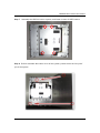
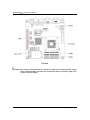
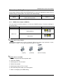
1
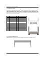
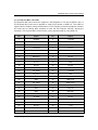
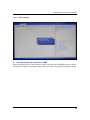
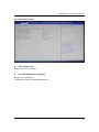
eBOX640-860-FL Series Embedded System User’s Manual Disclaimers This manual has been carefully checked and believed to contain accurate information. Axiomtek Co., Ltd. assumes no responsibility for any infringements of patents or any third party’s rights, and any liability arising from such use. Axiomtek does not warrant or assume any legal liability or responsibility for the accuracy, completeness or usefulness of any information in this document. Axiomtek does not make any commitment to update the information in this manual. Axiomtek reserves the right to change or revise this document and/or product at any time without notice No part of this document may be reproduced, stored in a retrieval system, or transmitted, in any form or by any means, electronic, mechanical, photocopying, recording, or otherwise, without the prior written permission of Axiomtek Co., Ltd. Copyright 2012 Axiomtek Co., Ltd. All Rights Reserved November 2012, Version A1 Printed in Taiwan ii Safety Precautions Before getting started, please read the following important safety precautions. 1. The eBOX640-860-FL does not come equipped with an operating system. An operating system must be loaded first before installing any software into the computer. 2. Be sure to ground yourself to prevent static charge when installing the internal components. Use a grounding wrist strap and place all electronic components in any static-shielded devices. Most electronic components are sensitive to static electrical charge. 3. Disconnect the power cord from the eBOX640-860-FL before making any installation. Be sure both the system and the external devices are turned OFF. Sudden surge of power could ruin sensitive components. Make sure the eBOX640-860-FL is properly grounded. 4. Make sure the voltage of the power source is correct before connecting the equipment to the power outlet. 5. Turn OFF the system power before cleaning. Clean the system using a cloth only. Do not spray any liquid cleaner directly onto the screen. 6. Do not leave this equipment in an uncontrolled environment where the storage temperature is below -20℃ or above 80℃. It may damage the equipment. 7. Do not open the system’s back cover. If opening the cover for maintenance is a must, only a trained technician is allowed to do so. Integrated circuits on computer boards are sensitive to static electricity. To avoid damaging chips from electrostatic discharge, observe the following precautions: Before handling a board or integrated circuit, touch an unpainted portion of the system unit chassis for a few seconds. This will help to discharge any static electricity on your body. When handling boards and components, wear a wrist-grounding strap, available from most electronic component stores. iii Classification 1. 2. 3. 4. iv Degree of production against electric shock : not classified Degree of protection against the ingress of water : IP30 Equipment not suitable for use in the presence of a flammable anesthetic mixture with air or with oxygen or nitrous oxide. Mode of operation : Continuous General Cleaning Tips You may need the following precautions before you begin to clean the computer. When you clean any single part or component for the computer, please read and understand the details below fully. When you need to clean the device, please rub it with a piece of dry cloth. 1. Be cautious of the tiny removable components when you use a vacuum cleaner to absorb the dirt on the floor. 2. Turn the system off before you start to clean up the component or computer. 3. Never drop the components inside the computer or get circuit board damp or wet. 4. Be cautious of all kinds of cleaning solvents or chemicals when you use it for the sake of cleaning. Some individuals may be allergic to the ingredients. 5. Try not to put any food, drink or cigarette around the computer. Cleaning Tools: Although many companies have created products to help improve the process of cleaning your computer and peripherals users can also use household items to clean their computers and peripherals. Below is a listing of items you may need or want to use while cleaning your computer or computer peripherals. Keep in mind that some components in your computer may only be able to be cleaned using a product designed for cleaning that component, if this is the case it will be mentioned in the cleaning. Cloth: A piece of cloth is the best tool to use when rubbing up a component. Although paper towels or tissues can be used on most hardware as well, we still recommend you to rub it with a piece of cloth. Water or rubbing alcohol: You may moisten a piece of cloth a bit with some water or rubbing alcohol and rub it on the computer. Unknown solvents may be harmful to the plastics parts. Vacuum cleaner: Absorb the dust, dirt, hair, cigarette particles, and other particles out of a computer can be one of the best methods of cleaning a computer. Over time these items can restrict the airflow in a computer and cause circuitry to corrode. Cotton swabs: Cotton swaps moistened with rubbing alcohol or water are excellent tools for wiping hard to reach areas in your keyboard, mouse, and other locations. Foam swabs: Whenever possible it is better to use lint free swabs such as foam swabs. Note: We strongly recommended that you should shut down the system before you start to clean any single components. Please follow the steps below: 1. 2. 3. 4. 5. Close all application programs Close operating software Turn off power switch Remove all device Pull out power cable v Scrap Computer Recycling If the computer equipment’s need the maintenance or are beyond repair, we strongly recommended that you should inform your Axiomtek distributor as soon as possible for the suitable solution. For the computers that are no longer useful or no longer working well, please contact your Axiomtek distributor for recycling and we will make the proper arrangement. Trademarks Acknowledgments Axiomtek is a trademark of Axiomtek Co., Ltd. IBM, PC/AT, PS/2, VGA are trademarks of International Business Machines Corporation. Intel® and Pentium® are registered trademarks of Intel Corporation. MS-DOS, Microsoft C and QuickBasic are trademarks of Microsoft Corporation. W indows 7, W indows Vista, W indows XPE, W indows XP, W indows W inCE embedded, Linux, MS-DOS, Microsoft C and Other brand names and trademarks are the properties and registered brands of their respective owners. vi Table of Contents Disclaimers .................................................................................................................................. ii Safety Precautions ...................................................................................................................... iii Classification............................................................................................................................... iv General Cleaning Tips ................................................................................................................. v Scrap Computer Recycling ......................................................................................................... vi CHAPTER 1 INTRODUCTION ......................................................................................................... 1 1.1 General Description .................................................................................................... 2 1.2 System Specifications................................................................................................. 3 1.2.1 CPU ........................................................................................................................... 3 1.2.2 I/O System ................................................................................................................. 3 1.2.3 Storage ...................................................................................................................... 3 1.2.4 System Specification .................................................................................................. 4 1.2.4 Driver CD Content ...................................................................................................... 5 1.3 Dimensions ................................................................................................................ 6 1.3.1 System Dimension ..................................................................................................... 6 1.3.2 Wall mount Bracket Dimension ................................................................................. 9 1.4 Dimensions .............................................................................................................. 12 1.4.1 I/O (Front) view ........................................................................................................ 12 1.4.2 I/O (Front) view Drawing .......................................................................................... 12 1.5 Packing List.............................................................................................................. 13 CHAPTER 2 HARDWARE INSTALLATION .................................................................................. 15 2.1 Installing the Memory Module .................................................................................. 16 2.2 Installing the CPU .................................................................................................... 19 2.3 Installing the SATA HDD .......................................................................................... 23 2.4 Installing the CFast .................................................................................................. 27 CHAPTER 3 JUMPER SETTING & CONNECTOR ....................................................................... 31 3.1 SBC layout ............................................................................................................... 32 3.2 Jumper Setting Summary ........................................................................................ 33 3.2.1 CMOS Clear Jumper (JCMOS1) ............................................................................. 33 3.3 Connectors ............................................................................................................... 34 3.3.1 Phoenix DC-in Connector ........................................................................................ 35 3.3.2 DC-in Jack Power Connector................................................................................... 35 3.3.3 PS2 Keyboard/Moues Connector............................................................................. 35 3.3.4 Serial Port Connector ............................................................................................... 36 3.3.5 DisplayPort Connector ............................................................................................. 37 3.3.6 VGA Connector ........................................................................................................ 38 3.3.7 HDMI Connector ...................................................................................................... 38 3.3.8 LAN Connector (LAN1, LAN2) ................................................................................. 39 3.3.9 USB Connector ........................................................................................................ 40 3.3.10 Audio Connector ...................................................................................................... 40 3.3.11 ATX Power On/OFF Button ..................................................................................... 40 3.3.12 SATA Connector (SATA2/SATA3) .......................................................................... 41 3.3.13 SATA Power Connector........................................................................................... 41 3.3.14 CFast™ Socket ....................................................................................................... 42 vii 3.3.15 DDR3 SODIMM Socket ........................................................................................... 42 3.3.16 Express Mini Card Slot ............................................................................................ 43 CHAPTER 4 BIOS SETUP UTILITY .............................................................................................. 45 4.1 Starting ..................................................................................................................... 46 4.2 Navigation Keys........................................................................................................ 46 4.3 Main Menu ................................................................................................................ 47 4.4 Advanced BIOS Setup ............................................................................................. 48 4.4.1 ACPI Settings ........................................................................................................... 49 4.4.2 Trusted computing ..................................................................................................... 50 4.4.3 CPU configuration ..................................................................................................... 51 4.4.4 SATA Configuration ................................................................................................... 52 4.4.5 PCH-FW Configuration.............................................................................................. 53 4.4.6 USB Configuration ..................................................................................................... 53 4.4.7 Super IO Configuration .............................................................................................. 54 4.4.7.1 Serial Port 0 configuration ........................................................................................ 55 4.4.7.2 Serial Port 1 configuration ........................................................................................ 56 4.4.7.3 Serial Port 2 configuration ........................................................................................ 57 4.4.7.4 Serial Port 3 configuration ........................................................................................ 58 4.4.8 Hardware Monitor ..................................................................................................... 59 4.5 Chipset ..................................................................................................................... 60 4.5.1 System Agent (SA) Configuration ............................................................................. 60 4.5.1.1 Config Graphic Settings............................................................................................ 61 4.5.1.2 Memory Configuration .............................................................................................. 62 4.5.2 P CH-IO Configuration................................................................................................. 63 4.5.2.1 USB Configuration .................................................................................................... 64 4.6 Boot .......................................................................................................................... 65 4.7 Security .................................................................................................................... 66 4.8 Save & Exit............................................................................................................... 67 viii MEMO: ix eBOX640-860-FL Series User’s Manual CHAPTER 1 INTRODUCTION This chapter contains general information and detailed specifications of the eBOX640-860-FL. The Chapter 1 includes the following sections: General Description System Specification Dimensions I/O Outlets Packing List Introduction 1 eBOX640-860-FL Series User’s Manual 1.1 General Description The eBOX640-860-FL is an embedded system that supports onboard dual core Intel ® nd rPGA988 socket G2 for 2 Generation Intel® Core™ i3/ i5/ i7/ Celeron® processor to provide W indows 7, W indows Vista, W indows XPE, Linux, suitable for the most endurable operation. It features fan less design with full feature I/O, two 204-pin unbuffered SODIMM socket for dual channel DDR3-1066/1333 MHz memory max. up to 16GB, and enhanced system dependability by built-in W atchdog Timer. Features 1. Intel® QM67 PCH 2. Support Intel® rPGA988 socket G2 for 2nd Generation Intel® Core™ i3/ i5/ i7/ Celeron® processor 3. Maximum to 16GB DDR3 1066/1333 MHz memory 4. Compact design 5. Supports 4 RS-232 Ports 6. Supports 6 USB 2.0 ports 7. Supports 2 10/100/1000Mbps Ethernet port 8. Dual 2.5” SATA HDD drive bays 9. One CFast™ 10. Watchdog timer 11. Wide Range DC-in support. ( DC 10~30V ) 12. Din-rail mount (optional) 13. Wall mount (optional) 14. VESA mount (optional) 15. Express Mini Card Module (optional) 16. Antenna (optional) 17. 19V 90W AC Power Adapter (optional) Reliable and Stable Design The eBOX640-860-FL adopts the advanced cooling system and supporting the CFast™, which makes it especially suitable for vibration environments, best for industrial automation, digital signage and gaming application. Embedded O.S. Supported The eBOX640-860-FL not only supports Windows 7, Windows Vista, but also supports embedded OS, such as WES, Win7 Embedded and Linux . Various Storage devices supported For storage device, the eBOX640-860-FL supports two 2.5" SATA storage drive bay, and one CFast™ slot. 2 Introduction eBOX640-860-FL Series User’s Manual 1.2 System Specifications 1.2.1 CPU CPU Support Intel® rPGA988 socket G2 for 2nd Generation Intel® Core™ i3/ i5/ i7/ Celeron® processor BIOS AMI 16Mb SPI System Memory Maximum to 16GB DDR3 memory Two 204-pin SODIMM support up to 16GB dual channel DDR3 1066/1333MHz sockets 1.2.2 I/O System Four 9-pin D-Sub male connectors, COM1~COM4 for RS-232 One 15-pin D-Sub female connector for VGA One DisplayPort One HDMI Port Allow configuration: VGA+ DisplayPort / VGA + HDMI / DisplayPort + HDMI One Audio connector Mic-IN, Line-OUT Two RJ-45 connector for 10/100/1000Base-T Ethernet Six USB 2.0 connectors One SMA type connector for antenna One phoenix type DC-in connector One lockable DC Jack connector (Optional for AC version) 1.2.3 Storage Two 2.5” SATA HDD/SSD drive bays One CFast™ slot Introduction 3 eBOX640-860-FL Series User’s Manual 1.2.4 System Specification Watchdog Timer Reset supported; 255 levels, 1~255 sec. Power Supply DC: 10~30V wide range DC input AC: 19V 90W AC/DC adapter Operation Temperature -5℃ ~ 50℃ (23 ºF ~ 122ºF), with W .T. HDD/SSD NOTE: The TDP of the processor should under 35W to prevent from over- heat Storage Temperature -20℃ ~ 80℃ (-4 ºF ~ 176ºF) Humidity 10% ~ 90% (non-condensation) Vibration Endurance 1Grm w/ HDD & SSD & CFast (5-500Hz, X, Y, Z directions) Weight 3.8 kg (8.37 lb) without package 4.6 kg (10.14 lb) with package Dimensions 192mm(7.56”) (W) x 230mm(9.05”) (D) x 100mm(3.93”) (H) 4 Introduction eBOX640-860-FL Series User’s Manual 1.2.4 Driver CD Content Driver Step 1_CHIP Step 2_VGA Step 3_ LAN Step 4_ AUDIO Step 5_RAID Step 6_TPM Step 7_ME Manual User Manual Quick Manual NOTE: After installed Intel Graphic/VGA Driver, the output display will become “Clone Display”. User can adjust the display device and resolution regarding to user’s requirement. NOTE: All specifications and images are subject to change without notice. Introduction 5 eBOX640-860-FL Series User’s Manual 1.3 Dimensions The following diagrams show you dimensions and outlines of the eBOX640-860-FL. 1.3.1 System Dimension Front View Rear View 6 Introduction eBOX640-860-FL Series User’s Manual Top View Bottom View Introduction 7 eBOX640-860-FL Series User’s Manual Side View 8 Introduction eBOX640-860-FL Series User’s Manual 1.3.2 Wall mount Bracket Dimension Front View Rear View Introduction 9 eBOX640-860-FL Series User’s Manual Top View Bottom View 10 Introduction eBOX640-860-FL Series User’s Manual Side View Introduction 11 eBOX640-860-FL Series User’s Manual 1.4 Dimensions The following figures show you I/O outlets on front view of the eBOX640-860-FL. 1.4.1 I/O (Front) view 1.4.2 I/O (Front) view Drawing 12 Introduction eBOX640-860-FL Series User’s Manual 1.5 Packing List The package bundled with your eBOX640-860-FL should contain the following items: eBOX640-860-FL System Unit x 1 eBOX640-860-FL Quick Manual x 1 CD x 1 (For Driver and User’s Manual) Screws pack x1 Foot pad x4 DC-in Phoenix Connector x1 Thermal Grease x1 W all-mount Brackets (optional) Din-rail Bracket (optional) 2.5” SATA HDD (optional) CFast™ card (optional) DDR3 SODIMM (optional) 19V 90W AC Power Adapter (optional) Power cord (optional) Express Mini Card (optional) Antenna (optional) Introduction 13 eBOX640-860-FL Series User’s Manual MEMO: 14 Introduction eBOX640-860-FL Series User’s Manual CHAPTER 2 HARDWARE INSTALLATION The eBOX640-860-FL is convenient for your various hardware configurations, such as rPGA988 socket processor, 204-pin DDR3 Memory Module, dual 2.5” HDD (Hard Disk Drive) or 2.5” SSD TM (Solid State Drive) and CFast card. The chapter 2 will show you how to install the hardware. Hardware Installation 15 eBOX640-860-FL Series User’s Manual 2.1 Installing the Memory Module Step 1 Turn off the system, and unplug the power cord. Step 2 Locate screws at the top cover, loosen screws. Step 3 Remove the top cover 16 Hardware Installation eBOX640-860-FL Series User’s Manual Step 4 Locate the memory module, insert the gold colored contact into the socket. Step 5 Push the module down, until it is firmly seated by locking two latches. Hardware Installation 17 eBOX640-860-FL Series User’s Manual Step 6 18 Close the cover to the chassis, and fasten all screws. Hardware Installation eBOX640-860-FL Series User’s Manual 2.2 Installing the CPU Step 1 Step 2 Turn off the system, and unplug the power cord. Locate screws at the top cover, loosen screws. Step 3 Remove the top cover Hardware Installation 19 eBOX640-860-FL Series User’s Manual Step 4 20 Before you install processor, please DO check the fool-proof pin. Hardware Installation eBOX640-860-FL Series User’s Manual Step 5 Turn the CPU lock clockwise to lock CPU Step 6 Install the processor, and then daub a layer of the thermal grease on the die of the processor and the chipset Hardware Installation 21 eBOX640-860-FL Series User’s Manual Step 7 22 Close the cover to the chassis, and fasten all screws. Hardware Installation eBOX640-860-FL Series User’s Manual 2.3 Installing the SATA HDD Step 1 Step 2 Turn off the system, and unplug the power cord. Turn the system upside down to locate screws at the Bottom, loosen screws. Step 3 Remove the bottom cover and Loosen screws of HDD bracket Hardware Installation 23 eBOX640-860-FL Series User’s Manual Step 5 Remove the HDD bracket Step 6 24 Assembly the HDD bracket together with the SATA HDD Hardware Installation eBOX640-860-FL Series User’s Manual Step 7 Connect SATA cable and SATA power cable with the SATA HDD Step 8 Assembly the HDD kit back to system, and fasten screws of HDD bracket Hardware Installation 25 eBOX640-860-FL Series User’s Manual Step 9 Before assemble the button cover of the system; please check the fool-proof pin of the system. Step 10 Close the cover to the chassis, and fasten all screws. 26 Hardware Installation eBOX640-860-FL Series User’s Manual 2.4 Installing the CFast Step 1 Step 2 Turn off the system, and unplug the power cord. Turn the system upside down to locate screws at the Bottom, loosen screws. Step 3 Remove the bottom cover and Loosen screws of HDD bracket Hardware Installation 27 eBOX640-860-FL Series User’s Manual Step 5 Remove the HDD bracket, and locate the CFast card slot. Step 6 28 Locate CFast slot and install the CFast card into CFast slot Hardware Installation eBOX640-860-FL Series User’s Manual Step 7 Assembly the HDD kit back to system, and fasten screws of HDD bracket Step 8 Before assemble the button cover of the system; please check the fool-proof pin of the system. Hardware Installation 29 eBOX640-860-FL Series User’s Manual Step 9 30 Close the cover to the chassis, and fasten all screws. Hardware Installation eBOX640-860-FL Series User’s Manual CHAPTER 3 JUMPER SETTING & CONNECTOR Proper jumper settings configure the eBOX640-860-FL to meet your application purpose. We are herewith listing a summary table of all jumpers and default settings for onboard devices, respectively. Jumper Setting & Connector 31 eBOX640-860-FL Series User’s Manual 3.1 SBC layout TOP Side NOTE: We strongly recommended that you should not modify any unmentioned jumper setting without Axiomtek FAE’s instruction. Any modification without instruction might cause system to become damage. 32 Jumper Setting & Connector eBOX640-860-FL Series User’s Manual 3.2 Jumper Setting Summary Proper jumper settings configure the eBOX640-860-FL to meet your application purpose. We are herewith listing a summary table of all jumpers and default settings. 3.2.1 Jumper Function / Default Setting Jumper Setting JCMOS1 Normal Operation/Clear CMOS setting Default: Normal Operation Short 1-2 CMOS Clear Jumper (JCMOS1) You may need to use this jumper is to clear the CMOS memory if incorrect settings in the Setup Utility. Description Function Jumper Setting Normal (Default) CMOS Clear Clear CMOS NOTE: How to setup Jumpers The illustration shows how to set up jumpers. W hen the jumper cap is placed on pins, the jumper is “close”, if not, that means the jumper is “open”. [Open] [Closed] [Pin1-2 Closed] NOTE: How to clear CMOS 1. Turn off the system and remove power cable. 2. Locate the JCMOS1. 3. Set the jumper to “Pin 2-3 close”. 4. Wait for five seconds. 5. Set the jumper back to “Pin 1-2 close”. 6. Re-connect the power cable, turn on the system. 7. Reset / re-configure your CMOS setting. Jumper Setting & Connector 33 eBOX640-860-FL Series User’s Manual 3.3 Connectors Connectors connect the system with other parts/devices. Loose or improper connection might cause problems. Make sure all connectors are properly and firmly connected. Below summary table shows you all connectors on the eBOX640-860-FL. External Connectors Section Phoenix DC-in Connector 3.3.1 DC-in Jack Power Connector 3.3.2 PS2 Keyboard/Moues Connector 3.3.3 Serial Port Connector 3.3.4 Display Port Connector 3.3.5 VGA Connector 3.3.6 HDMI Connector 3.3.7 LAN Connector(LAN1,LAN2) 3.3.8 USB Connector 3.3.9 Audio Connector 3.3.10 ATX Power On/Off Button 3.3.11 Internal Connectors Section SATA Connector 3.3.12 SATA Power Connector 3.3.13 CFast™ Socket 3.3.14 DDR3 SO-DIMM 3.3.15 Express Mini Card Slot 3.3.16 34 Jumper Setting & Connector eBOX640-860-FL Series User’s Manual 3.3.1 Phoenix DC-in Connector The system supports a wide range Phoenix DC-in connector for system power input. (Only for DC mode) Pin Signal 1 DC+ 2 GND 3 DC- 3.3.2 DC-in Jack Power Connector Connect it to the power AC/DC Adapter (only for AC mode) Pin Signal 1 DC Power 2 GND 3.3.3 PS2 Keyboard/Moues Connector The system provides a keyboard and Mouse interface that is a DIN connector. The PS/2 Mouser port is green, and the PS/2 Keyboard port of purple. NC VCC 4 6 3 NC 2 NC VCC NC Jumper Setting & Connector 4 PS/2 Mouse Clock 5 PS/2 Mouse Data 1 6 GND Keyboard Clock 5 3 GND Keyboard Data 2 1 35 eBOX640-860-FL Series User’s Manual 3.3.4 Serial Port Connector The system has four serial ports. COM1~4 are RS-232 port. Pin Description 1 2 3 4 5 6 7 8 9 Pin DCD, Data Carrier Detect RXD, Receive Data TXD, Transmit Data DTR, Data Terminal Ready GND, Ground DSR, Data Set Ready RTS, Request To Send CTS, Clear To Send RI, Ring Indicator Description 1 2 3 4 5 6 7 8 9 Pin DCD, Data Carrier Detect RXD, Receive Data TXD, Transmit Data DTR, Data Terminal Ready GND, Ground DSR, Data Set Ready RTS, Request To Send CTS, Clear To Send RI, Ring Indicator Description 1 2 3 4 5 6 7 8 9 Pin DCD, Data Carrier Detect RXD, Receive Data TXD, Transmit Data DTR, Data Terminal Ready GND, Ground DSR, Data Set Ready RTS, Request To Send CTS, Clear To Send RI, Ring Indicator Description 1 2 3 4 5 6 7 8 9 36 DCD, Data Carrier Detect RXD, Receive Data TXD, Transmit Data DTR, Data Terminal Ready GND, Ground DSR, Data Set Ready RTS, Request To Send CTS, Clear To Send RI, Ring Indicator COM1 COM2 COM3 COM4 Jumper Setting & Connector eBOX640-860-FL Series User’s Manual 3.3.5 DisplayPort Connector Display Port is a standard designed to replace digital (DVI) and analog component video (VGA) connectors in computer monitors and video cards, as well as replace internal digital LVDS links in computer monitor panels and TV panels. Pin Signal 1 DPB_LANE0 2 GND 3 DPB_LANE0# 4 DPB_LANE1 5 GND 6 DPB_LANE1# 7 DPB_LANE2 8 GND 9 DPB_LANE2# 10 DPB_LANE3 11 GND 12 DPB_LANE3# 13 Detect Pin 14 GND 15 DPB_AUX 16 GND 17 DPB_AUX# 18 DPB_HPDE 19 GND 20 +3.3V Jumper Setting & Connector 37 eBOX640-860-FL Series User’s Manual 3.3.6 VGA Connector The VGA connector is a slim type 15-pin D-Sub connector which is common for the CRT VGA display. The VGA interface configuration can be configured via the software utility. Pin Signal Pin Signal Pin Signal 1 Red 2 Green 3 Blue 4 N.C. 5 GND 6 DETECT 7 GND 8 GND 9 VCC 10 GND 11 N.C. 12 DDC DATA 13 Horizontal Sync 14 Vertical Sync 15 DDC CLK 3.3.7 HDMI Connector This 19-pin HDMI 1.3 port connects to a HDMI monitor . 38 Pin Signal Pin Signal Pin Signal 1 TMDS Data2+ 2 TMDS Data2 Shield 3 TMDS Data2– 4 TMDS Data1+ 5 TMDS Data1 Shield 6 TMDS Data1– 7 TMDS Data0+ 8 TMDS Data0 Shield 9 TMDS Data0– 10 TMDS Clock+ 11 TMDS Clock Shield 12 TMDS Clock– 13 CEC 14 Reserved 15 SCL 16 SDA 17 DDC/CEC Ground 18 +5 V Power 19 Hot Plug Detect Jumper Setting & Connector eBOX640-860-FL Series User’s Manual 3.3.8 LAN Connector (LAN1, LAN2) The RJ-45 connector is for Ethernet. To connect the board to a 1000/100/10 Base-T hub, just plug one end of the cable into connector and connect the other end (phone jack) to a 1000/100/10-Base-T hub Pin Signal Pin Signal A L1 MDI0+ L5 MDI2- L2 MDI0- L6 MDI1- L3 MDI1+ L7 MDI3+ L4 MDI2+ L8 MDI3- B L8 L7 L6 L5 L4 L3 L2 L1 SPEED LED ACT / LINK LED Status Description Status Description OFF 10Mbps connection OFF No link Orange 100Mbps connection Green Link Green 1Gbps connection Blinking Data activity Jumper Setting & Connector 39 eBOX640-860-FL Series User’s Manual 3.3.9 USB Connector These ports can be routed to UHCI controller #1 or EHCI controller #1. Pin Signal USB Port 0 Pin Signal USB Port 1 1 USB VCC (+5V level) 5 USB VCC (+5V level) 2 USB #0_D- 6 USB #1_D- 4 Ground (GND) 8 Ground (GND) 5 6 7 8 1 2 3 4 3.3.10 Audio Connector These two audio jacks ideal are for Audio Mic -In and Audio Line-out. Pin Signal 1 Line Out (Green) 2 Microphone In (Red) 3.3.11 ATX Power On/OFF Button The ATX power button is on the I/O side. It can allow users to control eBOX640-860-FL power on/off. Pin Signal 1 GND 1 2 2 40 PSIN Jumper Setting & Connector eBOX640-860-FL Series User’s Manual 3.3.12 SATA Connector (SATA2/SATA3) The SATA connector is for high-speed SATA interface ports and they can be connected to hard disk devices. Pin Signal 1 GND 2 SATA_TX+ 3 SATA_TX- 4 GND 5 SATA_RX- 6 SATA_RX+ 7 GND 3.3.13 SATA Power Connector The SATA Power connector is for SATA interface ports and they can provide power to hard disk devices. Pin Signal 1 +3.3VDC 2 +3.3VDC 3 +3.3VDC 4 COM 5 COM 6 COM 7 +5VDC 8 +5VDC 9 +5VDC 10 COM 11 COM 12 COM 13 +12VDC 14 +12VDC 15 +12VDC Jumper Setting & Connector 41 eBOX640-860-FL Series User’s Manual 3.3.14 CFast™ Socket TM TM The system is equipped with a CFast socket on the bottom side to support a CFast card which is based on the Serial ATA bus. The socket is specially designed to avoid TM TM incorrect installation of the CFast card. W hen installing or removing the CFast card, TM please make sure the system power is off. The CFast card by default identifies itself as C: or D: drive in your PC system. Pin Signal Pin Signal 1 GND 13 N.C 2 SATA_TX+ 14 GND 3 SATA_TX- 15 N.C 4 GND 16 CFAST_LED# 5 SATA_RX- 17 N.C 6 SATA_RX+ 18 N.C 7 GND 19 N.C 8 N.C 20 +3.3V Level 9 GND 21 +3.3V Level 10 N.C 22 GND 11 N.C 23 GND 12 N.C 24 N.C 3.3.15 DDR3 SODIMM Socket eBOX640-860-FL supports dual standard DDR3 204-pin MHz SO-DIMM sockets. 42 Jumper Setting & Connector eBOX640-860-FL Series User’s Manual 3.3.16 Express Mini Card Slot PCI Express Mini Card connector supports a PCI Express x1 link and a USB 2.0 link. A PCI Express Mini Card can be applied to either PCI Express or USB 2.0. The USB 2.0 support will be helpful during the transition to PCI Express, because peripheral vendors will need time to design their chipsets to have the PCI Express function. During the transition, PCI Express Mini Cards can be quickly imple mented by using USB 2.0. Pin Signal Pin Signal 1 W AKE# 2 +3.3VSB 3 No use 4 GND 5 No use 6 +1.5V 7 CLKREQ# 8 No use 9 GND 10 No use 11 REFCLK- 12 No use 13 REFCLK+ 14 No use 15 GND 16 No use 17 No use 18 GND 19 No use 20 No use 21 GND 22 PERST# 23 PE_RXN3 24 +3.3VSB 25 PE_RXP3 26 GND 27 GND 28 +1.5V 29 GND 30 SMB_CLK 31 PE_TXN3 32 SMB_DATA 33 PE_TXP3 34 GND 35 GND 36 USB_D8- 37 GND 38 USB_D8+ 39 +3.3VSB 40 GND 41 +3.3VSB 42 No use 43 GND 44 No use 45 No use 46 No use 47 No use 48 +1.5V 49 No use 50 GND 51 No use 52 +3.3VSB Jumper Setting & Connector 43 eBOX640-860-FL Series User’s Manual 44 Jumper Setting & Connector eBOX640-860-FL Series User’s Manual CHAPTER 4 BIOS SETUP UTILITY This chapter provides users with detailed description how to set up basic system configuration through the AMI BIOS setup utility. BIOS Setup Utility 45 eBOX640-860-FL Series User’s Manual 4.1 Starting To enter the setup screens, follow the steps below: 1. 2. Turn on the computer and press the <Del> key immediately. After you press the <Delete> key, the main BIOS setup menu displays. You can access the other setup screens from the main BIOS setup menu, such as the Chipset and Power menus. 4.2 Navigation Keys The BIOS setup/utility uses a key-based navigation system called hot keys. Most of the BIOS setup utility hot keys can be used at any time during the setup navigation process. These keys include <F1>, <F10>, <Enter>, <ESC>, <Arrow> keys, and so on. Note: Some of navigation keys differ from one screen to another. Key(s) 46 Function Description ← Select Screen ↑↓ Select Item +- Change Option / Field/ Value Enter Go to Sub Screen PGDN Next Page PGUP Previous Page HOME Go to Top of Screen END Go to Bottom of Screen F1 General Help F2 Previous Value F3 Optimized Default F4 Save & Exit Setup ESC Exit BIOS Setup Utility eBOX640-860-FL Series User’s Manual 4.3 Main Menu W hen you first enter the Setup Utility, you will enter the Main setup screen. You can always return to the Main setup screen by selecting the Main tab. There are two Main Setup options. They are described in this section. The Main BIOS Setup screen is shown below. BIOS Version Displays the auto-detected BIOS Version System Date The date format is <Date>,<Month>,<Day>,<Year>. System Time The time format is <Hour>,<Minute>,<Second>. Access Level Displays the accessory information. BIOS Setup Utility 47 eBOX640-860-FL Series User’s Manual 4.4 Advanced BIOS Setup Select the Advanced tab from the setup screen to enter the Advanced BIOS Setup screen. You can select any of the items in the left frame of the screen, such as Chipset configuration, to go to the sub menu for that item. You can display an Advanced BIOS Setup option by highlighting it using the <Arrow> keys. All Advanced BIOS Setup options are described in this section. The Advanced BIOS Setup screen is shown below. The sub menus are described on the following pages. Take caution when changing the settings of the Advanced menu items. Incorrect field values can cause the system to malfunction. 48 BIOS Setup Utility eBOX640-860-FL Series User’s Manual 4.4.1 ACPI Settings ACPI Sleep State [S3 (suspend to RAM)] Select the highest ACPI sleep state the system will enter the SUSPEND button is press. Configuration options: [Suspend Disable] [S1 (CPU Stop Clock)] [S3 (suspend to RAM)] BIOS Setup Utility 49 eBOX640-860-FL Series User’s Manual 4.4.2 Trusted computing Trusted computing (TPM) settings. TPM configuration TPM SUPPORT [Disabled] Enable or disable TPM support. Configuration options: [Disabled] [Enabled] Current TPM Status Information Displays the TPM status information 50 BIOS Setup Utility eBOX640-860-FL Series User’s Manual 4.4.3 CPU configuration CPU configuration Display the CPU information Limit CPUID Maximum [Disable] Disable for W indows XP. Configuration options: [Disabled] [Enabled] BIOS Setup Utility 51 eBOX640-860-FL Series User’s Manual 4.4.4 SATA Configuration SATA Controller(S)[Enable] Configuration options: [Enabled] [Disable] SATA Mode Selection [IDE] Support IDE, AHCI or RAID m ode Configuration options: [IDE][AHCI][RAID] Serial-ATA Port 1 [Compatible] Enabled/Disabled Serial-ATA Controller 1 Configuration options: [Disable] [Enhanced] [Compatible] Serial-ATA Port 2 [Enhanced] Enabled/Disabled Serial-ATA Controller 2 Configuration options: [Disable] [Enhanced] [Compatible] Serial-ATA Port 6 [Enhanced] Enabled/Disabled Serial-ATA Controller 6 Configuration options: [Disable] [Enhanced] [Compatible] 52 BIOS Setup Utility eBOX640-860-FL Series User’s Manual 4.4.5 PCH-FW Configuration Configuration Management Engine Technology Paramete r Display ME Firmware Information 4.4.6 USB Configuration USB Configuration Parameters BIOS Setup Utility 53 eBOX640-860-FL Series User’s Manual USB Device Display how many devices are connected. Legacy USB Support [Enabled] Enables Legacy USB support. AUTO option disables legacy support if no USB device s are connected. DISABLE option will keep USB devices available only for EFI applications. Configuration options: [Enabled] [Disabled] [Auto] EHCI Hand-off [Disable] This is a workaround for OSes without EHCI hand -off support. The EHCI ownership change should be claimed by EHCI driver. Configuration options: [Disabled] [Enabled] General USB Flash Disk 1.0 [Auto] Configuration options: [Auto] [Floppy] [Forced FDD] [Hard Disk] [CD-ROM] 4.4.7 Super IO Configuration System Super IO Chip Parameters. 54 BIOS Setup Utility eBOX640-860-FL Series User’s Manual Super IO Configuration Super IO Chip [NCT6776F] 4.4.7.1 Serial Port 0 configuration Set Parameters of Serial Port 0 (COM1) Serial Port 0 Configuration Serial Port [Enable] Enable or Disable Serial Port. Configuration options: [Disabled] [Enabled] Device Setting [IO=3F8h; IRQ=4] Change Setting [Auto] Select an optimal setting for Super IO device. Configuration options: [Auto] [IO=3F8h; IRQ=4] [IO=3F8h; IRQ=3, 4, 5, 6, 7, 9. 10, 11, 12] [IO=2F8h; IRQ=3, 4, 5, 6, 7, 9. 10, 11, 12] [IO=3E8h; IRQ=3, 4, 5, 6, 7, 9. 10, 11, 12] [IO=2E8h; IRQ=3, 4, 5, 6, 7, 9. 10, 11, 12] BIOS Setup Utility 55 eBOX640-860-FL Series User’s Manual 4.4.7.2 Serial Port 1 configuration Set Parameters of Serial Port 1 (COM2) Serial Port 1 Configuration Serial Port [Enable] Enable or Disable Serial Port. Configuration options: [Disabled] [Enabled] Device Setting [IO=C80h; IRQ=5] Change Setting [Auto] Select an optimal setting for Super IO device. Configuration options: [Auto] [IO=C80h; IRQ=5] [IO=C80h; IRQ=5, 7, 9. 10, 11] [IO=C88h; IRQ=5, 7, 9. 10, 11] [IO=C90h; IRQ=5, 7, 9. 10, 11] [IO=C98h; IRQ=5, 7, 9. 10, 11] 56 BIOS Setup Utility eBOX640-860-FL Series User’s Manual 4.4.7.3 Serial Port 2 configuration Set Parameters of Serial Port 2 (COM3) Serial Port 2 Configuration Serial Port [Enable] Enable or Disable Serial Port. Configuration options: [Disabled] [Enabled] Device Setting [IO=C88h; IRQ=5] Change Setting[Auto] Select an optimal setting for Super IO device. Configuration options: [Auto] [IO=C88h; IRQ=5] [IO=C80h; IRQ=5, 7, 9. 10, 11] [IO=C88h; IRQ=5, 7, 9. 10, 11] [IO=C90h; IRQ=5, 7, 9. 10, 11] [IO=C98h; IRQ=5, 7, 9. 10, 11] BIOS Setup Utility 57 eBOX640-860-FL Series User’s Manual 4.4.7.4 Serial Port 3 configuration Set Parameters of Serial Port 3 (COM4) Serial Port 3 Configuration Serial Port [Enable] Enable or Disable Serial Port. Configuration options: [Disabled] [Enabled] Device Setting [IO=C90h; IRQ=5] Change Setting [Auto] Select an optimal setting for Super IO device. Configuration options: [Auto] [IO=C90h; IRQ=5] [IO=C80h; IRQ=5, 7, 9. 10, 11] [IO=C88h; IRQ=5, 7, 9. 10, 11] [IO=C90h; IRQ=5, 7, 9. 10, 11] [IO=C98h; IRQ=5, 7, 9. 10, 11] 58 BIOS Setup Utility eBOX640-860-FL Series User’s Manual 4.4.8 Hardware Monitor PC Health Stutus Display system health status BIOS Setup Utility 59 eBOX640-860-FL Series User’s Manual 4.5 Chipset This Chipset tab is ideally for user to modify the chipset settings. 4.5.1 System Agent (SA) Configuration 60 BIOS Setup Utility eBOX640-860-FL Series User’s Manual System Agent RC version Display System Agent RC information. 4.5.1.1 Config Graphic Settings Primary Display [Auto] Select primary display output. Configuration options: [Auto] [IGFX] [PEG] [PCI] Internal Graphics [Auto] Keep IGD enable based on the setup option. Configuration options: [Disabled] [Enabled] Primary IGFX Boot Display [VBIOS Default] Select the output display device when boot up. Configuration options: [VBIOS Default] [CRT] [HDMI] [Display Port] DVMT Pre-Allocation [64M] Internal graphic memory size Configuration options: [0] [32M] [64M] [96M] [128M] [160M] [192M] [224M] [256M] [ 288M] [320M] [352M] [384M] [416M] [448M] [480M] [512M] BIOS Setup Utility 61 eBOX640-860-FL Series User’s Manual DVMT Total GFX Mem [256M] Select DVMT5.0 total graphic memory size. Configuration options: [128M] [256M] [MAX] 4.5.1.2 Memory Configuration Max TOLUD [Dynamic] Maximum Value of TOLUD Configuration options: [Dynamic] [1 GB] [1.25 GB] [1.5 GB] [1.75 GB] [2 GB] [2.25 GB] [2.5 GB] [2.75 GB] [3 GB] MRC Fast Boot [Enable] Enable or Disable MRC fast boot. Configuration options: [Disabled] [Enabled] 62 BIOS Setup Utility eBOX640-860-FL Series User’s Manual 4.5.2 PCH-IO Configuration PCH Parameters Intel PCH Information LAN1 Controller [Enable] Enable/Disable LAN1 Controller Configuration options: [Disabled] [Enabled] LAN1 Option-ROM [Disable] Enable/Disable LAN1 boot option for legacy network devices. Configuration options: [Disabled] [Enabled] Wake on LAN1 from S5 [Disable] Configuration options: [Disabled] [Enabled] LAN2 Controller [Enable] Enable/Disable LAN1 Controller Configuration options: [Disabled] [Enabled] BIOS Setup Utility 63 eBOX640-860-FL Series User’s Manual LAN2 Option-ROM [Disable] Enable/Disable LAN2 boot option for legacy network devices. Configuration options: [Disabled] [Enabled] Wake on LAN2 from S5 [Disable] Configuration options: [Disabled] [Enabled] 4.5.2.1 USB Configuration EHCI1 [Enabled] Enable/Disable USB 2.0(EHCI) support Configuration options: [Disabled] [Enabled] EHCI2 [Enabled] Enable/Disable USB 2.0(EHCI) support Configuration options: [Disabled] [Enabled] 64 BIOS Setup Utility eBOX640-860-FL Series User’s Manual 4.6 Boot Boot Configuration Setup Prompt Timeout [1] Number of seconds to wait for setup activation key. 65535(0xFFFF) means indefinite waiting. Quiet Boot [Disabled] Configuration options: [Disabled] [Enabled] Boot option priorities Select the system boot priorities. BIOS Setup Utility 65 eBOX640-860-FL Series User’s Manual 4.7 Security Administrator Password Set setup Administrator Password User Password Set User Password HDD Security Configuration Set possword tp secure HDD content. 66 BIOS Setup Utility eBOX640-860-FL Series User’s Manual 4.8 Save & Exit Save changes and Exit Exit system setup after saving the changes. Discard changes and Exit Exit system setup without saving the changes. Save changes and Reset Reset the system after saving the changes. Discard changes and Reset Reset the system without saving the changes. Save Changes Save changes done so for to any of the setup option. Discard changes Discard changes done so for to any of the setup option. Restore Defaults Restore/Load default values for all the setup option. BIOS Setup Utility 67 eBOX640-860-FL Series User’s Manual Save as User Defaults Save the changes done so far as User Defaults. Restore User Defaults Restore the user defaults to all the setup options Boot Override Display boot up device. 68 BIOS Setup Utility