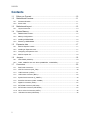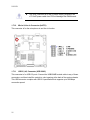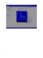
1
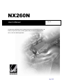
NX260N User’s Manual Ver 1.0 3rd Generation Intel® 32nm Atom™ N2600 Fanless Nano ITX Motherboard (Cedar Trail Platform) supports DC Power, provides greater battery life ideal for mobile/handheld device, retail and medical applications July 2012 NX260N Contents 1.1 1.2 Before you Proceed ..................................................................................................10 Motherboard Overview..............................................................................................11 1.2.1 Placement Direction..................................................................................................................... 11 1.2.2 Screw Holes ................................................................................................................................ 11 1.3 Motherboard Layout..................................................................................................12 1.3.1 1.4 System Memory ........................................................................................................14 1.4.1 DIMM Sockets Location ............................................................................................................... 14 1.4.2 Memory Configurations................................................................................................................ 14 1.4.3 Installing a DDR2 DIMM .............................................................................................................. 15 1.4.4 Removing a DDR2 DIMM ............................................................................................................ 16 1.5 Expansion slots .........................................................................................................17 1.5.1 MiniPCE Express Location .......................................................................................................... 17 1.5.2 Installing an Expansion Card ....................................................................................................... 17 1.5.3 Configuring an Expansion Card ................................................................................................... 17 1.5.4 MiniPCI express slot .................................................................................................................... 18 1.6 Jumpers ....................................................................................................................18 1.6.1 Clear CMOS (JCMOS1)............................................................................................................... 18 1.6.2 COM1, COM2 RI/+5V/+12V Select (JCOMPWR1, JCOMPWR2) ................................................ 19 1.7 2 Layout Content List...................................................................................................................... 13 Connectors................................................................................................................20 1.7.1 Rear Panel Connectors................................................................................................................ 20 1.7.2 CPU Fan Connector (SYS_FAN) ................................................................................................. 20 1.7.3 LVDS Connector (JLVDS) ........................................................................................................... 21 1.7.4 LCD Inverter Connector (JBKL1) ................................................................................................. 22 1.7.5 System Panel Connector (F_PANEL1) ........................................................................................ 23 1.7.6 Serial Port Connector (COM1 & COM2 ) ..................................................................................... 24 1.7.7 Digital I/O Connector (JDIO1) ...................................................................................................... 24 1.7.8 SATA Data Connector (SATA1&2) .............................................................................................. 25 1.7.9 SATA Power Connector (SATAPWR1) ........................................................................................ 25 1.7.10 Mic-In & Line-In Connector (AAFP1)........................................................................................... 26 1.7.11 USB 3&4 Connector (USB 23/45) ............................................................................................... 26 User’s Manual Safety Information Electrical safety To prevent electrical shock hazard, disconnect the power cable from the electrical outlet before relocating the system. When adding or removing devices to or from the system, ensure that the power cables for the devices are unplugged before the signal cables are connected. If possible, disconnect all power cables from the existing system before you add a device. Before connecting or removing signal cables from the motherboard, ensure that all power cables are unplugged. Seek professional assistance before using an adapter or extension cord. These devices could interrupt the grounding circuit. Make sure that your power supply is set to the correct voltage in your area. If you are not sure about the voltage of the electrical outlet you are using, contact your local power company. If the power supply is broken, do not try to fix it by yourself. Contact a qualified service technician or your retailer. Operation safety Before installing the motherboard and adding devices on it, carefully read all the manuals that came with the package. Before using the product, make sure all cables are correctly connected and the power cables are not damaged. If you detect any damage, contact your dealer immediately. To avoid short circuits, keep paper clips, screws, and staples away from connectors, slots, sockets and circuitry. Avoid dust, humidity, and temperature extremes. Do not place the product in any area where it may become wet. Place the product on a stable surface. If you encounter technical problems with the product, contact a qualified service technician or your retailer. The symbol of the crossed out wheeled bin indicates that the product (electrical and electronic equipment) should not be placed in municipal waste. Check local regulations for disposal of electronic products. NX260N 3 NX260N Safety Declaration This device complies with the requirements in Part 15 of the FCC rules. Operation is subject to the following two conditions: This device may not cause harmful interference. This device must accept any interference received, including interference that may cause undesired operation. Technical Support If a problem arises with your system and no solution can be obtained from the user’s manual, please contact your place of purchase or local distributor. Alternatively, please try the following help resources for further guidance. Visit the BCM website: http://www.bcmcom.com Conventions Used in This Guide To make sure that you perform certain tasks properly, take note of the following symbols used throughout this manual. DANGER/WARNING: Information to prevent injury to yourself when trying to complete a task. CAUTION: Information to prevent damage to the components when trying to complete a task. IMPORTANT: Instructions that you MUST follow to complete a task. NOTE: Tips and additional information to help you complete a task. 4 User’s Manual Packing List Before you begin installing your single board, please make sure that the following materials have been shipped: 1 x NX260N Nano-ITX Motherboard 1 x CD-ROM contains the followings: User’s Manual in PDF file Drivers 1 x Cable Kit 2 x COM Cable w/o Bracket (9P/2.00mm) 1 x SATA CABLE 7P 2IN1 L:500mm 1 x SATA power cable (ATX 2x2P) 1 x Startup Manual If any of the above items is damaged or missing, please contact your retailer. NX260N 5 NX260N Revision History Revision 6 Revision History Date V 0.1 First version for PCB 1.0 July, 2012 V 0.2 Add BIOS section Aug ,2012 User’s Manual Specifications Summary Specifications System CPU Onboard Intel® Atom™ N2600 1.6GHz Processor FSB DMI (2.5Gbps) x 4 Lanes BIOS AMI/Legacy 16 Mb SPI BIOS System Chipset Intel® NM10 I/O Chipset Winbond W83627DHG-A Memory Watchdog Timer H/W Status Monitor One 204-pin SODIMM socket supports up to 2GB DDR3 1066/1333 MHz SDRAM Reset: 1 to 255 sec/min per step Monitoring CPU temperature, voltage, and cooling fan status. Auto throttling control when CPU overheats Expansion Slots 1 x Mini PCIe DIO 8-bit General Purpose I/O for 4 DI and 4 DO S3 / S4 S1, S3, S4, S5 Wake up on LAN or Ring LAN (PXE), RING (COM1/2) SmartFan Control Supports 3 modes (Silent/Optimal/Performance) Display Chipset Integrated Intel® GMA 3600 Graphic Core Display Memory Shared Memory Max 1GB Max. Resolution LVDS : Max 1280 x 800 or 1366 x 768 VGA : Max 2048 x 1536 @ 60Hz Dual Display LVDS+VGA VGA On board LVDS 18-bit Single Channel LVDS LVDS Backlight Power 5V and 12V Audio Audio Codec Realtek ALC892, 5.1 + 2 CH HD Audio Audio Interface Line out (jack) , Mic. In & Line in (pin header) Ethernet LAN1 Realtek RTL 8111E Gigabit LAN * Specifications are subject to change without notice. NX260N 7 NX260N Block Diagram 8 User’s Manual This chapter describes the main board features and the new technologies it supports. 1 Product introduction NX260N 9 NX260N Production Introduction 1.1 Before you Proceed Take note of the following precautions before you install motherboard components or change any motherboard settings. 10 Unplug the power cord from the wall socket before touching any component. Use a grounded wrist strap or touch a safely grounded object or a metal object, such as the power supply case, before handling components to avoid damaging them due to static electricity Hold components by the edges to avoid touching the ICs on them. Whenever you uninstall any component, place it on a grounded antistatic pad or in the bag that came with the component. Before you install or remove any component, ensure that the ATX power supply is switched off or the power cord is detached from the power supply. Failure to do so may cause severe damage to the motherboard, peripherals, and/or components. User’s Manual 1.2 Motherboard Overview Before you install the motherboard, study the configuration of your chassis to ensure that the motherboard fits into it. Refer to the chassis documentation before installing the motherboard. Make sure to unplug the power cord before installing or removing the motherboard. Failure to do so can cause you physical injury and damage motherboard components. 1.2.1 Placement Direction When installing the motherboard, make sure that you place it into the chassis in the correct orientation. The edge with external ports goes to the rear part of the chassis as indicated in the image below. 1.2.2 Screw Holes Place four (4) screws into the holes indicated by circles to secure the motherboard to the chassis. Do not over tighten the screws! Doing so can damage the motherboard. Place this side towards the rear of the chassis. NX260N 11 NX260N 1.3 Motherboard Layout 12 User’s Manual 1.3.1 Layout Content List Slots Label Function Note Page SO_DIMM_2 204-pin DDR3 SODIMM slot (Rear side) 15 CN2 Mini PCI-e Slot (Rear side) 18 Jumpers Label Function Note Page JMOS1 Clear CMOS 3 x 1 header, pitch 2.54mm 19 JCOMPWR1 COM1 RI/+5V/+12V Select 3 x 2 header, pitch 2.00mm 20 JCOMPWR2 COM1 RI/+5V/+12V Select 3 x 2 header, pitch 2.00mm 20 Note Page Rear Panel Connector Label Function PS1 12V DC-In Power Jack Pin ψ2.5mm 21 VGA1 VGA Connector D-sub 15-pin, female 21 USB01 USB 1&2 Connector 21 LAN1 RJ-45 Ethernet Connector 21 Audio Audio Line-out Port 21 Internal Connector Label Function Note Page SYS_FAN CPU Fan Connector 3 x 1 wafer, pitch 2.54mm 22 JLVDS LVDS Connector Hirose DF13S-40DP-1.25V 22 JBKL1 LCD Inverter Connector 5 x 1 header, pitch 2.00mm 23 F_PANEL1 System Panel Connector (USB 5&6) 8 x 2 header, pitch 2.00mm 24 COM1 & 2 Serial Port Connector * 2 5 x 2 header, pitch 2.00mm 25 JDIO1 Digital I/O Connector 5 x 2 header, pitch 2.00mm 25 SATA1 & 2 SATA Data Connector * 2 7P Male connector 26 SATAPWR1 SATA Power Connector 2 x 2 female box header 26 AAFP1 Mic-In & Line-In Connector 5 x 2 header, pitch 2.00mm 27 USB23/45 USB Connector 5 x 2 header, pitch 27 2.00/2.54mm NX260N 13 NX260N 1.4 System Memory 1.4.1 DIMM Sockets Location The motherboard comes with two 200-pin Double Data Rate 3 (DDR3) SODIMM sockets. A DDR3 module has the same physical dimensions as a DDR2 DIMM but has a 204-pin footprint compared to the 200-pin DDR DIMM. DDR3 DIMMs are notched differently to prevent installation on a DDR2 DIMM socket. The following figure illustrates the location of the sockets: 1.4.2 Memory Configurations You can install 1GB and 2GB DDR3 SDRAM DIMMs into the SODIMM sockets using the memory configurations in this section. 14 Installing DDR3 DIMM other than the recommended configurations may cause memory sizing error or system boot failure. Use any of the recommended configurations. Due to chipset graphic resource allocation, the system may detect less than 2 GB system memory when you installed one 2 GB DDR3 memory modules. This motherboard does not support memory modules FSB less than 1066MHz.Make sure that the memory frequency matches the CPU FSB (Front Side Bus). Refer to the Memory frequency/CPU FSB synchronization table. User’s Manual 1.4.3 Installing a DDR3 DIMM Make sure to unplug the power supply before adding or removing DIMMs or other system components. Failure to do so may cause severe damage to both the motherboard and the components. 1. Locate the DIMM socket on the board. 2. Hold two edges of the DIMM module carefully, and keep away of touching its connectors. 3. Align the notch key on the module with the rib on the slot. 4. Firmly press the modules into the socket which will automatically snap into the mounting notch. Do not force the DIMM module in with extra force as the DIMM module only fits in one direction. A DDR3 DIMM is keyed with a notch so that it fits in only one direction. DO NOT force a DIMM into a socket to avoid damaging the DIMM. The DDR3 DIMM sockets do not support DDR/DDR2 DIMMs. DO NOT install DDR/DDR2 DIMMs to the DDR3 DIMM socket. NX260N 15 NX260N 1.4.4 Removing a DDR3 DIMM 1. Press the two ejector tabs on the slot outward simultaneously, and then pull out the DIMM module. Support the DIMM lightly with your fingers when pressing the ejector tabs. The DIMM might get damaged when it flips out with extra force. 16 User’s Manual 1.5 Expansion slots 1.5.1 MiniPCE Express Location In the future, you may need to install expansion cards. The following sub-sections describe the slots and the expansion cards that they support. Make sure to unplug the power cord before adding or removing expansion cards. Failure to do so may cause you physical injury and damage motherboard components. 1.5.2 Installing an Expansion Card 1. Before installing the expansion card, read the documentation that came with it and make the necessary hardware settings for the card. 2. Remove the system unit cover (if your motherboard is already installed in a chassis). 3. Remove the bracket opposite the slot that you intend to use. Keep the screw for later use. 4. Align the card connector with the slot and press firmly until the card is completely seated on the slot. 5. Secure the card to the chassis with the screw you removed earlier. 6. Replace the system cover. 1.5.3 Configuring an Expansion Card After installing the expansion card, configure it by adjusting the software settings. 1. Turn on the system and change the necessary BIOS settings, if any. See Chapter 2 for information on BIOS setup. 2. Assign an IRQ to the card if needed. Refer to the tables on the next page. 3. Install the software drivers for the expansion card. NX260N 17 NX260N 1.5.4 MiniPCI express slot The miniPCI express slot supports Mini cards for WiFi , Bluetooth, SSD, COM, USB modules, and other cards that comply with the mini Card Rev. 1.2 specifications . The figure below shows the type of full size SSD card that can be installed on a miniPCI express slot. Due to different pin definitions between mini Card Rev. 1.0 to 1.1/1.2 , some Rev.1.0 mini Cards may not work normally on this MiniPCI express slot . 1.6 Jumpers 1.6.1 Clear CMOS (JCOMS1) This jumper allows you to clear the Real Time Clock (RTC) RAM in CMOS. You can clear the CMOS memory of date, time, and system setup parameters by erasing the CMOS RTC RAM data. The onboard button cell battery powers the RAM data in CMOS, which include system setup information such as system passwords. To erase the RTC RAM: 1. Turn OFF the computer and unplug the power cord. 2. Remove the onboard battery. 3. Move the jumper cap from pins 1-2 (default) to pins 2-3. Keep the cap on pins 2-3 for about 5~10 seconds, then move the cap back to pins 1-2. 4. Re-install the battery. 5. Plug the power cord and turn ON the computer. 6. Hold down the <Del> key during the boot process and enter BIOS setup to re-enter data. Except when clearing the CMOS, never remove the cap on the CLRTC jumper default position. Removing the cap will cause system boot failure! 18 User’s Manual Normal (Default) 1 Clear CMOS 1 1.6.2 COM1, COM2 RI/+5V/+12V Select (JCOMPWR1, JCOMPWR2) RI (Default) 6 5 +5V 6 5 +12V 5 6 NX260N 19 NX260N 1.7 Connectors 1.7.1 No 1 Rear Panel Connectors OS1 Label Function 12V DC-In Power Jack 2 VGA1 VGA Connector 3 USB01 USB 1&2 connector 4 LAN1 LAN (RJ-45) connector Description This power jack is connecting for 12V AC/DC pin 2.5mm power adapter . 12V 40W above is recommended . This 15-pin port is for a VGA monitor or other VGA-compatible devices. These two 4-pin Universal Serial Bus (USB) ports are available for connecting USB 1.1/2.0 devices. This port allows Gigabit connection to a Local Area Network (LAN) through a network hub. Refer to the table below for the LAN port LED indications. The optional 10/100 Mbps LAN controller allows 10/100 Mbps connection to a Local Area Network (LAN) through a network hub. SPEED LED Status 5 Audio ACT / LINK LED Description Status Description OFF 10Mbps connection OFF No link Orange 100Mbps connection Green Link Green 1Gbps connection Blinking Data activity Audio Line-out Port This port connects a headphone or a speaker. In 4-channel, 6-channel, and 8-channel configuration, the function of this port becomes Front Speaker Out. 1.7.2 CPU Fan Connector (SYS_FAN) This connector supports 12V smart fan for onboard heat-sink. 20 User’s Manual Do not forget to connect the fan cable to the fan connector. Insufficient air flow inside the system may damage the motherboard components. This is not a jumper! DO NOT place a jumper cap on the fan connector. 1.7.3 LVDS Connector (JLVDS) This motherboard supports 18-bit single channel LVDS panel. NX260N 21 NX260N 1.7.4 LCD Inverter Connector (JBKL1) This function will support the control of internal LVDS brightness. Signal Description Signal VR Signal Description For inverter with adjustable Backlight function, it is possible to control the LCD brightness through the VR signal. Vadj=0.75V ~ 4.25V (Recommended: 4.7KΩ, > 1/16W) ENBKL 22 LCD backlight ON/OFF control signal User’s Manual 1.7.5 System Panel Connector (F_PANEL1) This connector supports several chassis-mounted functions, and provides additional USB 5 & 6 ports. System Power LED (2-pin PWRLED) This 2-pin connector is for the system power LED. Connect the chassis power LED cable to this connector. The system power LED lights up when you turn on the system power, and blinks when the system is in sleep mode. ATX Power Button/Soft-off Button (2-pin PWRSW) This connector is for the system power button. Pressing the power button turns the system on or puts the system in sleep or soft-off mode depending on the BIOS settings. Pressing the power switch for more than four seconds while the system is ON turns the system OFF. Hard Disk Drive Activity LED (2-pin HDLED) This 2-pin connector is for the HDD Activity LED. Connect the HDD Activity LED cable to this connector. The IDE LED lights up or flashes when data is read from or written to the HDD. Reset Button (2-pin RESET) This 2-pin connector is for the chassis-mounted reset button for a system reboot without turning off the system power. NX260N 23 NX260N 1.7.6 Serial Port Connector (COM1 & COM2 ) These 2 connectors are for serial (COM) port. Connect the serial port module cable to this connector, and then install the module to a slot opening at the back of the system chassis. COM 1&2 1.7.7 Digital I/O Connector (JDIO1) This connector supports 8-bit General purpose I/O function. 24 User’s Manual 1.7.8 SATA Data Connector (SATA1&2) These connectors are for the SATA signal cables to link SATA hard disk drives. SATA 1&2 1.7.9 SATA Power Connector (SATAPWR1) This connector is for the provided SATA power cable. This power supply cable is designed to fit this connector in only one orientation. Find the proper orientation and push down firmly until the connector completely fits. NX260N 25 NX260N This 2x2P connector is for SATA power supply, plugging-in an ATX 2x2P power cable from PSU will damage this motherboard . 1.7.10 Mic-In & Line-In Connector (AAFP1) This connector is for the microphone-in and line-in function. 1.7.11 USB 2,3,4,5 Connector (USB 23/45) This connector is for USB 2.0 ports. Connect the USB/GAME module cable to any of these connectors, and then install the module to a slot opening at the back of the system chassis. This USB connector complies with USB 2.0 specification that supports up to 480 Mbps connection speed. 26 User’s Manual Never connect a 1394 cable to the USB connectors. Doing so will damage the motherboard! The USB module is purchased separately. 1.7.12 Amplifier Connector (JAMP1) NX260N 27 NX260N This chapter tells how to change the system settings through the BIOS setup menus. Detailed descriptions of the BIOS parameters are also provided. 2 BIOS setup 28 User’s Manual BIOS Setup 2.1 BIOS Setup Program This motherboard supports a programmable firmware chip that you can update using the provided utility. Use the BIOS Setup program when you are installing a motherboard, reconfiguring your system, or prompted to “Run Setup.” This section explains how to configure your system using this utility. Even if you are not prompted to use the Setup program, you can change the configuration of your computer in the future. For example, you can enable the security password feature or change the power management settings. This requires you to reconfigure your system using the BIOS Setup program so that the computer can recognize these changes and record them in the CMOS RAM of the firmware hub. The firmware hub on the motherboard stores the Setup utility. When you start up the computer, the system provides you with the opportunity to run this program. Press <Del> during the Power-On-Self-Test (POST) to enter the Setup utility; otherwise, POST continues with its test routines. If you wish to enter Setup after POST, restart the system by pressing <Ctrl+Alt+Delete>, or by pressing the reset button on the system chassis. You can also restart by turning the system off and then back on. Do this last option only if the first two failed. The Setup program is designed to make it as easy to use as possible. Being a menu-driven program, it lets you scroll through the various sub-menus and make your selections from the available options using the navigation keys. The default BIOS settings for this motherboard apply for most conditions to ensure optimum performance. If the system becomes unstable after changing any BIOS settings, load the default settings to ensure system compatibility and stability. Select the Load Optimized Defaults from the BIOS menu screen. The BIOS setup screens shown in this section are for reference purposes only, and may not exactly match what you see on your screen. Visit the system builder’s website to download the latest BIOS file for this motherboard NX260N 29 NX260N 2.1.1 Legend Box The keys in the legend bar allow you to navigate through the various setup menus Key(s) Function Description ← Select Screen ↑↓ Select Item +- Change Option / Field Enter Go to Sub Screen PGDN Next Page PGUP Previous Page HOME Go to Top of Screen END Go to Bottom of Screen F2/F3 Change Colors F7 Discard Changes F8 N/A F9 Load Optimal Defaults F10 Save and Exit ESC Exit 2.1.2 List Box This box appears only in the opening screen. The box displays an initial list of configurable items in the menu you selected. 2.1.3 Sub-menu Note that a right pointer symbol appears to the left of certain fields. This pointer indicates that you can display a sub-menu from this field. A sub-menu contains additional options for a field parameter. To display a sub-menu, move the highlight to the field and press <Enter>. The sub-menu appears. Use the legend keys to enter values and move from field to field within a sub-menu as you would within a menu. Use the <Esc> key to return to the main menu. Take some time to familiarize yourself with the legend keys and their corresponding functions. Practice navigating through the various menus and submenus. If you accidentally make unwanted changes to any of the fields, press <F9> to load the optimal default values. While moving around through the Setup program, note that explanations appear in the Item Specific Help window located to the right of each menu. This window displays the help text for the currently highlighted field. 30 User’s Manual 2.2 BIOS Menu Screen When you enter the BIOS, the following screen appears. The BIOS menu screen displays the items that allow you to make changes to the system configuration. To access the menu items, press the up/down/right/left arrow key on the keyboard until the desired item is highlighted, then press [Enter] to open the specific menu. NX260N 31 NX260N 32 User’s Manual 2.2.1 Main Use this menu for basic system configurations, such as time, date etc. 2.2.1.1 System Time The time format is <Hour> <Minute> <Second>. 2.2.1.2 System Date The date format is <Day>, <Month> <Date> <Year>. NX260N 33 NX260N 2.1 Advanced BIOS Setup Select the Advanced tab from the setup screen to enter the Advanced BIOS Setup screen. You can select any of the items in the left frame of the screen, such as Chipset configuration, to go to the sub menu for that item. You can display an Advanced BIOS Setup option by highlighting it using the <Arrow> keys. All Advanced BIOS Setup options are described in this section. The Advanced BIOS Setup screen is shown below. The sub menus are described on the following pages. Take caution when changing the settings of the Advanced menu items. Incorrect field values can cause the system to malfunction. 34 User’s Manual 2.4.1 ACPI Settings ACPI Sleep State [S3 (suspend to RAM)] Select the highest ACPI sleep state the system will enter the SUSPEND button is press. Configuration options: [Suspend Disable][S1 (CPU Stop Clock)] [S3 (suspend to RAM )] Resume on RI [Disabled] Enable or Disable Resume on Ring Function Configuration options: [Disabled] [Enabled] Wake on LAN Control [Disable] Configuration options: [Disabled] [Enabled] Resume On RTC Alarm [Disable] Enable or disable system wake on alarm even. When enabled, system will wake upon the hr/min/sec specified. Configuration options: [Disabled] [Enabled] NX260N 35 NX260N 2.4.3 CPU configuration CPU configuration Displays the CPU information Hyper-threading [Enabled] Enable or disable Hyper-threading support. Configuration options: [Disabled] [Enabled] Execute Disable Bit [Enable] XD can prevent certain classes of malicious buffer overflow attacks when combined with a supporting OS ( Windows Server 2003 SP1, Windows XP SP2, SuSE Linux 9.2 RedHat Enterprise 3 Update 3.) Configuration options: [Disabled] [Enabled] Limit CPUID Maximum [Disable] Disable for Windos XP. Configuration options: [Disabled] [Enabled] 36 User’s Manual 2.4.5 IDE Configuration SATA Controller (S) [Enhanced] Enabled/Disabled SATA Controllers Configuration options: [Disable] [Enhanced] [Compatible] Configure SATA as [IDE Mode] Support IDE, AHCI or RAID mode Configuration options: [Disable][IDE Mode][AHCI Mode][RAID Mode] NX260N 37 NX260N 2.4.6 USB Configuration USB Configuration Parameters USB Device Display how many devices are connected. Legacy USB Support [Enabled] Enables Legacy USB support. AUTO option disables legacy support if no USB devices are connected. DISABLE option will keep USB devices available only for EFI applications. Configuration options: [Enabled] [Disabled][Auto] EHCI Hand-off [Disable] This is a workaround for OSes without EHCI hand-off support. The EHCI ownership change should be claimed by EHCI driver. Configuration options: [Disabled] [Enabled] USB Transfer time-out [20 sec] The time-out value for Control, Bulk, and Interrupt transfers. 38 User’s Manual Device reset time-out [20 sec] USB mass Storage device start Unit command time-out. Device power-up delay [Auto] Maximum time the device will take before it properly reports itself to the Host Controller. ‘Auto’ uses default value: for a Root port it is 100ms, for a Hub port the delay is taken from Hub descriptor. 2.4.9 Super IO Configuration System Super IO Chip Parameters. Super IO Configuration Super IO Chip [W83627DHG] NX260N 39 NX260N 2.4.10.1 Serial Port 1 configuration Set Parameters of Serial Port 1 (COMA) Serial Port 1 Configuration Serial Port [Enable] Enable or Disable Serial Port. Configuration options: [Disabled] [Enabled] Device Setting [IO=3F8h; IRQ=4] Change Setting[Auto] Select an optimal setting for Super IO device. Configuration options: [Auto] [IO=3F8h; IRQ=4] [IO=3F8h; IRQ=3, 4, 5, 6, 7, 9. 10, 11, 12] [IO=2F8h; IRQ=3, 4, 5, 6, 7, 9. 10, 11, 12] [IO=3E8h; IRQ=3, 4, 5, 6, 7, 9. 10, 11, 12] [IO=2E8h; IRQ=3, 4, 5, 6, 7, 9. 10, 11, 12] 2.4.10.2 Serial Port 2 configuration Set Parameters of Serial Port 2 (COMA) 40 User’s Manual Serial Port 2 Configuration Serial Port [Enable] Enable or Disable Serial Port. Configuration options: [Disabled] [Enabled] Device Setting [IO=2F8h; IRQ=3] Change Setting[Auto] Select an optimal setting for Super IO device. Configuration options: [Auto] [IO=2F8h; IRQ=3] [IO=3F8h; IRQ=3, 4, 5, 6, 7, 9. 10, 11, 12] [IO=2F8h; IRQ=3, 4, 5, 6, 7, 9. 10, 11, 12] [IO=3E8h; IRQ=3, 4, 5, 6, 7, 9. 10, 11, 12] [IO=2E8h; IRQ=3, 4, 5, 6, 7, 9. 10, 11, 12] NX260N 41 NX260N 2.4.11 Hardware Monitor PC Health Stutus Display system health status Smart Fan Function [Enable] Enable or Disable Smart Fan Function Configuration options: [Disabled] [Enabled] 2.4.10.7 Smart Fan Mode Configruation Smart Fan Mode configuration 42 User’s Manual System Smart Fan Target [Disable] Select system Fan mode Configuration options: [Disable] [Thermal Cruise Mode][SNART FAN IV Mode] NX260N 43 NX260N 2.4.12 PPM Configuration EIST:[Enabled] Intel Speed Step technology option, the action needs perform under ACPI -based OS. CPU C-State Report [Enabled] Use this item to enable or disable CPUC-state report to OS. Enhanced C-state [Enabled] Use this item to enable or disable enhanced CPU C-state. CPU Hard C4E This item allows users to enable or disabled CPU Hard C4E function. CPU C6 state This item allows users to enable or disabled CPU C6 state. 44 User’s Manual C4 Exit Timing [Fast] This option controls a programmable time for the CPU voltage to stabilize when exiting from a C4 state. C-state POPDOWN This item allows users to enable or disabled Intel C-state POPDOWN function. C-state POPUP This item allows users to enable or disabled Intel C-state POPUP function. 2.2 Chipset NX260N 45 NX260N 2.5.1 Host Bridge Memory Information Display Memory Information 46 User’s Manual 2.5.1.1 Memory Frequency and Timing MRC Fast Boot [Enabled] Bypasses longer memory training routines during system re-BOOT. Can help speed up BOOT times. Max TOLUD [Dynamic] Maximum Value of TOLUD. Dynamic assignment would adjust TOLUD automatically based on largest MMIO length of installed graphic controller NX260N 47 NX260N 2.5.1.2 Display Configuration 48 User’s Manual 2.5.2 South Bridge Onboard LAN Controller [Enabled] Enable/Disable LAN1 Controller Configuration options: [Disabled] [Enabled] DMI Link ASPM Control [Enabled] Enable or disable the control of Active State Power Management on SA side of the DMI Link. The choice: Disable, L0s, L1, L0sL1 High Precision Timer [Enable] Enable/Disable the High Precision Timer Configuration options: [Disabled] [Enabled] SLP_S4 Assertion Width [1~2 Seconds] Select a minimum assertion width of the SLP_S4 signal NX260N 49 NX260N 2.5.2.1 TPT Device Azalia HD Audio [HD Audio] Enable/Disable Azalia HD Audio Configuration options: [Disabled] [HD Audio][Default] Audio Amplifier [21.2 db] Select USB Mode[By Controllers] Select USB mode to control USB ports. Configuration options:[By Ports][By Controllers][Default] UHCI # 1 [Enabled] Control the USB UHCI (USB 1.1) functions. Disable from highest to lowest Controller Configuration options: [Disabled] [Enabled] 50 UHCI # 2 [Enabled] User’s Manual Control the USB UHCI (USB 1.1) functions. Disable from highest to lowest Controller Configuration options: [Disabled] [Enabled] UHCI # 3 [Enabled] Control the USB UHCI (USB 1.1) functions. Disable from highest to lowest Controller Configuration options: [Disabled] [Enabled] USB 2.0(EHCI) Support [Enabled] Enable or Disable USB 2.0 (EHCI) Support SMBus Controller [Enable] Enable/Disable SMBus controller. Configuration options: [Disabled] [Enabled] 2.3 Boot Boot Configuration NX260N 51 NX260N Setup Prompt Timeout [1] Number of seconds to wait for setup activation key. 65535(0xFFFF) means indefinite waiting. Bootup NumLock State [On] Select the keyboard NumLock state Configuration options: [On] [Off] Quick Boot [Disable] Configuration options: [Disable] [Enable] CSM16 Module Version [07.64] Display CSM16 Module Version. Boot option priorities [Built-in EFI Shell] Select the system boot order. Configuration options: [Built-in EFI Shell][Disabled] 52 User’s Manual 2.4 Security Administrator Password Set setup Administrator Password User Password Set User Password NX260N 53 NX260N 2.5 Save & Exit Save changes and Exit Exit system setup after saving the changes. Discard changes and Exit Exit system setup without saving the changes. Save changes and Reset Reset the system after saving the changes. Discard changes and Reset Reset the system without saving the changes. Save changes Save changes done so for to any of the setup option. 54 User’s Manual Discard changes Discard changes done so for to any of the setup option. Restore Defaults Restore/Load default values for all the setup option. Save as User Defaults Save the changes done so far as User Defaults. Restore User Defaults Restore the user defaults to all the setup options NX260N 55