Download Quick-start Guide - Cyber-Rain
Transcript
D1 Windows: On your PC, open the Network or
TM
My Network folder. This is typically found in the Start
Menu or Computer Folder. Select Other Devices
(Windows 7, Vista) or Show Icons for Networked UPnP
Devices (XP). Double Click the Cyber-Rain Gateway Icon.
The Irrigation Controller With A Brain
Mac OS: On your MAC, download and open the gateway
discover program from http://cyber-rain.com/downloads/
mac/Cyber-Rain.dmg. Double click on the Cyber-Rain
Gateway Finder icon. After downloading, double click your
gateway in the Cyber-Rain Gateway Browser List.
The complete installation guide can be
found at www.cyber-rain.com/support
For technical support, call (877) 888-1452
Quick Start Setup Guide
D2 The Cyber-Rain Gateway
screen will appear in your
browser. Click the here link
for the Cyber-Rain Server.
D3 The Cyber-Rain log-in
screen will appear.
Select Register Now and
create an account.
D4 The Cyber-Rain Controller
Discovery Screen will appear
as Cyber-Rain automatically
finds your controller(s).
Complete for each controller.
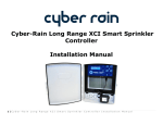
Cyber-Rain XCI Cloud Smart Sprinkler Controller
Your Cyber-Rain XCI kit should contain the following:
A. Controller
B. Mounting Hardware
C. Valve Sensor
Harness(es)
(Two for 16 Zone)
D. Gateway Access Point
E. Gateway Power Adapter
F. Ethernet Cable
G. Controller AC Adapter
H. Serial Number Sheet
I. Mounting Holes Template
J. Rain Sensor Harness
K. Flow Sensor Harness
(Pro Model Only)
A
J
K
B
C
D5 The Cyber-Rain Cloud software will appear. Set watering day
preferences on the Site tab. Input your watering schedule for
the hottest time of year directly on the Controller tab or let
Cyber-Rain suggest a water-wise schedule on the Zone tab.
E
F
D
G
Cyber-Rain installation is now complete!
See the user manual on the Help page of the Cloud software for more detailed
instructions. To return to your account, select Log-In at www.cyber-rain.com.
v5.0
Revised 5/6/11
Installing the Cyber-Rain Smart Controller
The ideal location to install the controller is probably where your existing
controller is now. Otherwise, look for a place in the garage that is protected
from heat, dirt, and moisture. If you plan to install outdoors, you will need to
protect your Cyber-Rain controller in a plastic outdoor box (available at most
Cyber-Rain resellers). Install the controller away from large metal objects or
transformers that can interfere with the wireless transmission.
A1
A3
B3
Insert the AC Adapter (item G)
connector into the Controller and
plug the other end into an electrical
outlet. Note that the flat side of
the power connector should face
the front of the controller for proper
insertion (figure 4).
Carefully remove the sprinkler wires
from your existing controller.
figure 4
(Please make a note of the wire colors for each zone.)
A2
Connecting the Cyber-Rain Smart Controller (Cont.)
Use the Mounting Holes Template
(item J) as a guideline for mounting the
two screws into the wall (figure 1).
If placing on drywall, drill a hole sized
1/4” into the wall to set the anchor.
Insert the 2 screws provided (item B)
with a Philips screw driver. Once both
screws are in place, carefully align the
holes in the rear of the controller over
the screws, then slide into place.
(figure 2)
figure 1
figure 2
Manually test your sprinkler controller. There are five buttons on the front of
the controller. Pushing SELECT will turn ON the indicated zone for 30 seconds.
Pressing UP will add time to the selection. Pressing DOWN will decrease the
time. Pushing the SELECT button a second time will turn that zone OFF. Use
the right/left ARROWS to move between zones.
A rain sensor can also be connected to your controller to automatically shut off
the controller for an adjustable period of time. In the Pro version there is also
an optional flow sensor to shutoff your system in the event of an over/under
flow.
Installing the Cyber-Rain Gateway
C1
Connecting the Cyber-Rain Smart Controller
NOTE: The notches on the harness must be facing towards
the front of the controller (see figure 3).
B1
Insert the sprinkler wires into the wire harness (see figure 3). The
common or “ground” wire is normally colored WHITE and should be
inserted into the left most slot of the harness. Each additional wire is
inserted from left to right starting with zone 1 going through zone 8.
B2
After all wires have been inserted into the
corresponding slots and tightened firmly
with a 1/8” or smaller slotted screwdriver,
insert the harness into the slot in the
controller. If you have the 16 zone
model, repeat the process for zones 9
to 16 in the smaller harness, and plug
into the bottom slot of the controller.
figure 3
Plug one end of your Ethernet Cable (item F) into your Gateway
Access Point (item D) and the other end into an available
Ethernet port on your internet router or modem. Connect one
end of the Gateway Power Adapter (item E) to the
Gateway Access Point and plug the other into a wall socket. All
LED lights on the Gateway Access Point should illuminate
momentarily and the yellow LED light should remain on.


