1
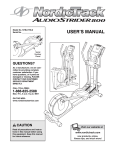
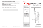
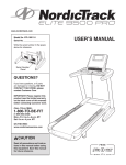
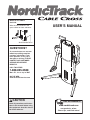
Model No. 831.6002.0
Serial No.
Write the serial number in the
space above for future reference.
USER’S MANUAL
Serial Number Decal
QUESTIONS?
As a manufacturer, we are committed to providing complete
customer satisfaction. If you
have questions, or if a part is
damaged or missing, PLEASE
CONTACT OUR CUSTOMER
SERVICE DEPARTMENT
DIRECTLY.
CALL TOLL-FREE:
1-888-825-2588
Mon.–Fri., 6 a.m.–6 p.m. MST
ON THE WEB:
www.nordictrackservice.com
CAUTION
Read all precautions and instructions in this manual before using
this equipment. Save this manual
for future reference.
Visit our website at
www.nordictrack.com
new products, prizes,
fitness tips, and much more!
TABLE OF CONTENTS
WARNING DECAL PLACEMENT . . . . . . . . . . . . . . . . . . . . . . . . . . . . . . . . . . . . . . . . . . . . . . . . . . . . . . . . . . . . . 2
IMPORTANT PRECAUTIONS . . . . . . . . . . . . . . . . . . . . . . . . . . . . . . . . . . . . . . . . . . . . . . . . . . . . . . . . . . . . . . . . 3
BEFORE YOU BEGIN . . . . . . . . . . . . . . . . . . . . . . . . . . . . . . . . . . . . . . . . . . . . . . . . . . . . . . . . . . . . . . . . . . . . . . 4
ASSEMBLY . . . . . . . . . . . . . . . . . . . . . . . . . . . . . . . . . . . . . . . . . . . . . . . . . . . . . . . . . . . . . . . . . . . . . . . . . . . . . . 5
ADJUSTMENTS . . . . . . . . . . . . . . . . . . . . . . . . . . . . . . . . . . . . . . . . . . . . . . . . . . . . . . . . . . . . . . . . . . . . . . . . . . . 7
CABLE DIAGRAM . . . . . . . . . . . . . . . . . . . . . . . . . . . . . . . . . . . . . . . . . . . . . . . . . . . . . . . . . . . . . . . . . . . . . . . . . .9
PART LIST . . . . . . . . . . . . . . . . . . . . . . . . . . . . . . . . . . . . . . . . . . . . . . . . . . . . . . . . . . . . . . . . . . . . . . . . . . . . . .10
EXPLODED DRAWING . . . . . . . . . . . . . . . . . . . . . . . . . . . . . . . . . . . . . . . . . . . . . . . . . . . . . . . . . . . . . . . . . . . . .11
ORDERING REPLACEMENT PARTS . . . . . . . . . . . . . . . . . . . . . . . . . . . . . . . . . . . . . . . . . . . . . . . . . .Back Cover
LIMITED WARRANTY . . . . . . . . . . . . . . . . . . . . . . . . . . . . . . . . . . . . . . . . . . . . . . . . . . . . . . . . . . . . . . Back Cover
WARNING DECAL PLACEMENT
The decals shown here have been
placed on the weight system. If a
decal is missing or illegible, please
call the toll-free telephone number on
the front cover of this manual and
order a free replacement decal. Apply
the decal in the location shown.
NordicTrack is a registered trademark of ICON IP, Inc.
2
IMPORTANT PRECAUTIONS
WARNING:
To reduce the risk of serious injury, read the following important precautions
before using the weight system.
1. Read all instructions in this manual and all
warnings on the weight system before using
the weight system. Use the weight system
only as described in this manual.
6. Inspect and properly tighten all parts regularly. Replace any worn parts immediately.
7. Keep children under 12 and pets away from
the weight system at all times.
2. It is the responsibility of the owner to ensure
that all users of the weight system are adequately informed of all precautions.
8. Always wear athletic shoes for foot protection while exercising.
3. The weight system is intended for home use
only. Do not use the weight system in any
commercial, rental, or institutional setting.
9. Make sure that the cable remains on the pulleys at all times. If the cable binds as you are
exercising, stop immediately and make sure
that the cable is on the pulleys.
4. Keep the weight system indoors, away from
moisture and dust. Place the weight system
on a level surface, with a mat beneath it to
protect the floor or carpet. Make sure that
there is enough clearance around the weight
system to use the weight system.
10. Always make sure that the weight pin is
inserted fully into the weight stack before
exercising.
11. If you feel pain or dizziness at any time while
exercising, stop immediately and begin cooling down.
5. Keep hands and feet away from moving parts.
WARNING:
Before beginning this or any exercise program, consult your physician. This
is especially important for persons over the age of 35 or persons with pre-existing health problems.
Read all instructions before using. ICON assumes no responsibility for personal injury or property
damage sustained by or through the use of this product.
3
BEFORE YOU BEGIN
reading this manual, see the front cover of this manual. To help us assist you, please note the product
model number and serial number before calling. The
model number is 831.6002.0. The serial number can
be found on a decal attached to the weight system
(see the front cover of this manual).
Thank you for selecting the versatile NORDICTRACK®
CABLE CROSS weight system. The weight system
offers a selection of weight stations designed to develop every major muscle group of the body. Whether
your goal is to tone your body, build dramatic muscle
size and strength, or improve your cardiovascular system, the weight system will help you to achieve the
specific results you want.
Before reading further, please review the drawing
below and familiarize yourself with the parts that are
labeled.
For your benefit, read this manual carefully before
using the weight system. If you have questions after
Counterweights
Adjustment Bracket
Arm
Knob
Left Side
Right Side
Frame
Swivel Arm
Weights
Cable
ASSEMBLED DIMENSIONS:
Height: 90 in. / 229 cm
Width: 66 in. / 168 cm
Depth: 54 in. / 137 cm
Note: The terms “right side” and “left side” are
determined relative to a person facing away
from the system; they do not correspond to
right and left on the drawings in this manual.
4
ASSEMBLY
• As you assemble the weight system, make sure
all parts are oriented as shown in the drawings.
Make Things Easier for Yourself
Everything in this manual is designed to ensure
that the weight system can be assembled successfully by anyone. Most people find that by
setting aside plenty of time, assembly will go
smoothly.
An Allen wrench and the following tools (not
included) are required for assembly:
• Two adjustable wrenches
• One standard screwdriver
Before beginning assembly, carefully read the
following information and instructions:
• One Phillips screwdriver
• Lubricant (three grease packs are included).
• Assembly requires two people.
Assembly will be more convenient if you have a
socket set, a set of open-end or closed-end
wrenches, or a set of ratchet wrenches.
• Place all parts in a cleared area and remove the
packing materials. Do not dispose of the packing
materials until assembly is completed.
• Tighten all parts as you assemble them, unless
instructed to do otherwise.
1.
1
Before beginning assembly, make sure you
understand the information in the box
above. Important: Some of the parts
described in the assembly steps may be
pre-assembled.
Attach a Stabilizer (3) to the bottom of the Frame
(1), as shown, with four 3/8” x 3 1/2” Button Bolts
(58), eight 3/8” SAE Washers (55), and four 3/8”
Nylon Locknuts (63).
58
Attach the other Stabilizer (3) to the other side
of the Frame (1) in the same manner.
55
55
See the inset drawing. If the floor beneath the
weight system is not even, level the weight
system by placing 1 5/8” x 2 1/2” x 1/8”
Spacers (83) between the appropriate Rubber
Feet (50) and the Stabilizer (3), and replacing
the #8 x 3/4” Screws (not shown) with #8 x 1”
Screws (84).
1
3
63
55
55
55
55
58
63
55
55
83
50
84
5
3
3
2. Remove the Shroud (not shown) from the back of
the weight system. (Note: The cover on the
Frame [1] is shown removed for clarity; the
cover cannot be removed.) Next, remove the
four indicated 1/4” x 2 1/2” Bolts (59) from the
Frame. Remove the Weight Guides (16).
2
16
5 81
Lubricate the insides of the welded tubes on the
Top Weight (15) with the included grease.
59
81
5
60
See the inset drawing. Position the Arms (19,
20) as shown (see ADJUSTING THE ARMS, on
page 7). Attach the two ends of the Cable (33)
together with two Cable Clips (10).
15
Welded
Tubes
Place the two Weight Bumpers (4) over the indicated holes in the bottom of the Frame (1). Insert
the two included dowels (not shown) into the
Weight Bumpers and the Frame. Slide the five
20-pound Weights (13) and the nine 10-pound
Weights (14) onto the dowels. Note: Make sure
that the Weights are stacked in order so that
the 10-pound Weight marked “1 5” is on top,
and the 20-pound Weight marked “15 100” is
on the bottom.
Weight Selector
Remove a dowel (not shown) from the stack of
Weights (13, 14). Reinsert a Weight Guide (16)
into the Frame (1) and the holes in the Weights.
Repeat with the other Weight Guide. Secure
the Weight Guides to the Frame with the four 1/4”
x 2 1/2” Bolts (59), the four 1/4” Washers (81), the
four Weight Guide Spacers (5), and the four 1/4”
Nylon Locknuts (60).
20
14
81
59
13
81
5
4
60
1
33
19
10
Disconnect the ends of the Cable (33) and lower
the Top Weight (15), so that the weight selector is
inserted into the middle hole in the stack of
Weights (13, 14).
3
Make sure the Cable Traps (78) are oriented as
shown in the CABLE DIAGRAM on page 9.
Replace the Shroud (not shown).
10
3. Attach a Handle (9) to a Cable Eye (37) with a
Cable Clip (10). Attach the other Handle to the
other Cable Eye in the same manner.
9
4. Make sure that all parts have been properly
tightened. The use of the remaining parts will
be explained in ADJUSTMENTS, beginning on
the following page.
6
37
ADJUSTMENTS
This section explains how to adjust the weight system. Refer to the accompanying exercise guide to see the correct form for each exercise.
Make sure that all parts are properly tightened each time the weight system is used. Replace any worn parts
immediately. The weight system can be cleaned with a damp cloth and a mild, non-abrasive detergent. Do not
use solvents.
CHANGING THE WEIGHT SETTING
To change the weight setting of the weight stack,
insert the Weight Pin (12) under the desired Weight
(13, 14). Make sure to insert the Weight Pin until the
bent end of the Weight Pin is touching the Weights,
and turn the bent end upward. Note: The weight
system works best when at least two weights are
used.
14
12
13
ADJUSTING THE ARMS
The Arms (19, 20) can be adjusted to any of eleven
positions for different exercises. To position an Arm,
first pull the Knob (32) out as far as it will go. Move
the Arm to the desired position, and then engage the
Knob into a hole in the Adjustment Bracket (23, 24).
24
23
32
20
32
19
7
TIGHTENING THE CABLE
Woven cable, the type of cable used on the weight
system, can stretch slightly when it is first used. If
there is slack in the Cable (33) when the arms are in
the straight up position before resistance is felt, the
Cable should be tightened. Note: There will be slack
in the Cable when the arms are in any other position.
77
33
34
63
Slack can be removed from the Cable (33) by moving
either or both of the indicated 4 1/2” Pulleys (34) in
the brackets on the Top Weight (15). First, remove
the Shroud (not shown). Then, loosen a 3/8” x 2 1/2”
Bolt (77) and a 3/8” Nylon Locknut (63), and move
the Pulley down. Finally, make sure the Cable Traps
(78) are oriented as shown in the CABLE DIAGRAM on page 9, and retighten the Bolt and Nylon
Locknut. Replace the Shroud.
34
78
63
15
Bracket
CHANGING ACCESSORIES
A Handle (9) or the Ankle Strap (not shown) can be
attached to a Cable Eye (37) with a Cable Clip (10).
Attach the other Handle to the other Cable Eye in the
same manner.
37
10
9
REINSTALLING THE CABLE
If the cable tends to slip off the pulleys, the cable may have become twisted. Remove the cable and reinstall it.
1. Create slack in the cable by removing the weight pin and pulling one of the handles out six to eight inches.
Insert the weight pin into the third weight plate and the tube on the bottom of the top weight.
2. Push the black rubber coupler cover off the aluminum coupler and slide the cover up the cable to contact the
swivel arm.
3. Loosen the four 1/4” x 1/4” screws in the coupler and pull the cable free.
4. Remove the cable from the weight system.
5. Reinstall the cable. (Refer to the CABLE DIAGRAM on page 9 for proper cable routing.)
6. Reinsert the cable and the sheath into the coupler so that all of the bare cable is in the hole.
7. Retighten the four screws into the threaded holes. Tighten the screws equally until they contact the cable.
Then, tighten each screw alternately 1/4 turn, until all are set to 85 inch-pounds (9.6 Newton-meters).
8. Slide the rubber coupler cover over the coupler, remove the weight pin, and lower the handle.
Note: If the cable needs to be replaced, see ORDERING REPLACEMENT PARTS on the back cover of this
manual.
8
CABLE DIAGRAM
The cable diagram shows the proper routing of the
cable. Use the diagram to make sure that the cable
and the cable traps have been assembled correctly. If
the cable has not been correctly routed, the weight
system will not function properly and damage may
occur. The numbers show the correct route for the
cable. Make sure that the cable traps do not touch
or bind the cable. Note: The indicated cable traps
on pulleys 4 and 7 should be in a five o’clock
position, as shown.
6
8
5
3
9
2
7
4
Cable
Trap
10
1
9
PART LIST—Model No. 831.6002.0
Key No.
Qty.
1
2
3
4
5
6
7
8
9
10
11
12
13
14
15
16
17
18
19
20
21
22
23
24
25
26
27
28
29
30
31
32
33
34
35
36
37
38
39
40
41
42
43
44
45
1
1
2
2
4
1
1
1
2
2
6
1
5
9
1
2
2
2
1
1
2
2
1
1
2
4
4
4
2
18
4
2
1
10
2
2
2
1
2
4
2
2
10
4
2
Description
R0405A
Key No. Qty.
Frame
Frame Handle
Stabilizer
Weight Bumper
Weight Guide Spacer
Left Side Cover
Right Side Cover
Frame Handle Pad
Handle
Cable Clip
Weight Guide Bushing
Weight Pin
20-pound Weight
10-pound Weight
Top Weight
Weight Guide
Swivel Arm
Trunnion
Left Arm
Right Arm
.507” x 1.50” x .66” Spacer
Counterweight
Left Adjustment Bracket
Right Adjustment Bracket
.507” x 1.50” x 1.17” Spacer
.39” x .625” x 1.08” Spacer
.39” x .625” x 1.59” Spacer
Pulley Plate
Pulley Disc
10-pound Weight Bushing
Spacer Cap
Knob
Cable
4 1/2” Pulley
3 1/2” Pulley
Coupler Cover
Cable Eye
Shroud
Bungee Cord
Pulley Arm Bearing
Top Weight Top Bushing
Top Weight Bottom Bushing
20-pound Weight Bushing
3/8” Locknut
Cable Bearing
46
47
48
49
50
51
52
53
54
55
56
57
58
59
60
61
62
63
64
65
66
67
68
69
70
71
72
73
74
75
76
77
78
79
80
81
82
83
84
#
#
#
#
#
2
2
2
2
4
10
2
2
2
30
8
4
8
4
4
2
2
26
10
2
2
4
4
4
2
2
2
4
4
8
2
2
6
4
2
4
1
4
4
1
1
1
3
2
Description
Inner C-clip
Coupler
Spring Washer
Outer C-clip
Rubber Foot
#8 x 3/4” Screw
Top Weight Bumper
1/4” x 3/4” Screw
3/8” Star Washer
3/8” SAE Washer
3/8” USS Washer
3/8” x 5” Button Screw
3/8” x 3 1/2” Button Bolt
1/4” x 2 1/2” Bolt
1/4” Nylon Locknut
3/8” x 1 3/4” Button Bolt
3/8” Jamnut
3/8” Nylon Locknut
3/8” x 2” Bolt
3/8” x 1” Bolt
1/4” x 3/4” Bolt
3/8” x 4 1/2” SHC Screw
1/2” Jamnut
Plastic Spacer
Bungee Cord Attachment
1/2” x 1 1/2” Button Screw
1/2” x 2” Button Screw
5/16” x 1 3/4” Button Screw
5/16” SAE Washer
1/4” x 1/4” Screw
3/8” x 3 3/4” Bolt
3/8” x 2 1/2” Bolt
Cable Trap
2” Washer
Magnetic Strip
1/4” Washer
Ankle Strap
1.625” x 2.5” x .125” Spacer
#8 x 1” Screw
User’s Manual
Exercise Guide
Allen Wrench
Grease Pack
Dowel
Note: “#” indicates a non-illustrated part. Specifications are subject to change without notice. See the back cover
of this manual for information about ordering replacement parts.
10
EXPLODED DRAWING—Model No. 831.6002.0
67
67
28
29
27
28
22
29
68
55
26
31
39
24
51 21
32
20
70
69 73 71
79
48
49
62
34 55
56
44
57
31 63
47
44
78 55
63
63
11
37
45
44
64 34 63 46
75
47
59
78
5 81 11
80
19
48
49
75 18
34 40
36
5
62
55
11
66
33
60
75
66
65
58
39
4
55 1
11 4
11
50
50
59
84
83
5
63
55
10
60
63
54
15
42
30
55 55
51
50
51
11
53
77
78
54
42
30
13
50
55 3
77
52
58
82
78
41
53
52
81
51 55
80
78 34
83
51
16
70
63
3
81
17
51
6
58
55
55
61
8
2
9
25
81
7
36
38
32
76
64
63
23
22
21
34
37
45
44
46
75
31 69
64
34
33 17 55
67
69
40
61
55
63
72
79
73 68
74
79
71
64
73
74
55 56
55
73 57
74
63 56
72
18
63
31 69
63
74
79
55
57
27
26
56 35
64
35
25
28 34 28
26
34
R0405A
12
14
34
78
63
43
ORDERING REPLACEMENT PARTS
To order replacement parts, see the front cover of this manual. To help us assist you, please be prepared to give
the following information:
• the MODEL NUMBER of the product (831.6002.0)
• the NAME of the product (NordicTrack CABLE CROSS weight system)
• the SERIAL NUMBER of the product (see the front cover of this manual)
• the KEY NUMBER and DESCRIPTION of the part(s) (see the PART LIST and EXPLODED DRAWING on
pages 10 and 11 of this manual)
LIMITED WARRANTY
WHAT IS COVERED—The entire NordicTrack CABLE CROSS weight system (“Product”) is warranted to be free of all defects in
material and workmanship.
WHO IS COVERED—The original purchaser or any person receiving the Product as a gift from the original purchaser.
HOW LONG IS IT COVERED—ICON Health & Fitness, Inc. (“ICON”), warrants the product for one year after the date of purchase.
Labor is covered for one year.
WHAT WE DO TO CORRECT COVERED DEFECTS—We will ship to you, without charge, any replacement part or component, providing the repairs are authorized by ICON first and are performed by an ICON trained and authorized service provider, or, at our
option, we will replace the Product.
WHAT IS NOT COVERED—Any failures or damage caused by unauthorized service, misuse, accident, negligence, improper
assembly or installation, alterations, modifications without our written authorization or by failure on your part to use, operate, and
maintain as set out in your User’s Manual (“Manual”).
WHAT YOU MUST DO—Always retain proof of purchase, such as your bill of sale; store, operate, and maintain the Product as specified in the Manual; notify our Customer Service Department of any defect within 10 days after discovery of the defect; as instructed, return any defected part for replacement or, if necessary, the entire product, for repair.
USER’S MANUAL—It is VERY IMPORTANT THAT YOU READ THE MANUAL before operating the Product. Remember to do the
periodic maintenance requirements specified in the Manual to assure proper operation and your continued satisfaction.
HOW TO GET PARTS AND SERVICE—Simply call our Customer Service Department at 1-888-825-2588 and tell them your name
and address and the serial number of your Product. They will tell you how to get a part replaced, or if necessary, arrange for service where your Product is located or advise you how to ship the Product for service. Before shipping, always obtain a Return
Authorization Number (RA No.) from our Customer Service Department; securely pack your Product (save the original shipping carton if possible); put the RA No. on the outside of the carton and insure the product. Include a letter explaining the product or problem and a copy of your proof of purchase if you believe the service is covered by warranty.
ICON is not responsible or liable for indirect, special or consequential damages arising out of or in connection with the use or performance of the product or damages with respect to any economic loss, loss of property, loss of revenues or profits, loss of enjoyment or use, costs of removal, installation or other consequential damages of whatsoever nature. Some states do not allow the
exclusion or limitation of incidental or consequential damages. Accordingly, the above limitation may not apply to you.
The warranty extended hereunder is in lieu of any and all other warranties and any implied warranties of merchantability or fitness
for a particular purpose is limited in its scope and duration to the terms set forth herein. Some states do not allow limitations on how
long an implied warranty lasts. Accordingly, the above limitation may not apply to you.
No one is authorized to change, modify or extend the terms of this limited warranty. This warranty gives you specific legal rights and
you may have other rights which vary from state to state.
ICON HEALTH & FITNESS, INC., 1500 S. 1000 W., LOGAN, UT 84321-9813
Part No. 226971 R0405A
Printed in USA © 2005 ICON IP, Inc.