1
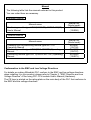
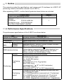
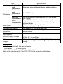
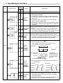
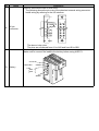
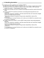
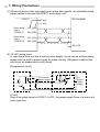
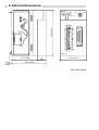
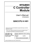
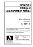
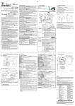
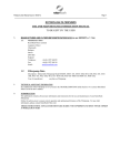
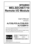
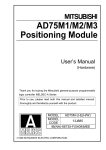
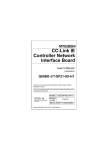
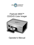
Positioning Module type A1SD71-S7 User’s Manual (Hardware) Thank you for purchasing the Mitsubishi programmable logic controller MELSEC-A Series. Prior to use, please read both this manual and detailed manual thoroughly to fully understand the product. MODEL A1SD71-S7(H/W)-U-E MODEL 13JE50 CODE IB(NA)-66489-C(0507)MEE 1994 MITSUBISHI ELECTRIC CORPORATION z SAFETY PRECAUTIONS z (Be sure to read these instructions before using the product.) Before using this product, read this manual and the relevant manuals introduced in this manual carefully and handle the product correctly with full attention to safety. Note that these precautions apply only to this product. Refer to the user's manual of the CPU module for the PLC system safety precautions. DANGER Indicates that incorrect handling may cause hazardous conditions, resulting in death or severe injury. CAUTION Indicates that incorrect handling may cause hazardous conditions, resulting in minor or moderate injury or property damage. Note that failure to observe the CAUTION level instructions may also lead to serious results according to the circumstances. Be sure to observe the instructions of both levels to ensure personal safety. Please save this manual to make it accessible when required and always forward it to the end user. [DESIGN PRECAUTIONS] DANGER z Configure a safety circuit so that the safety of the overall system is maintained even when an external power error or PLC error occurs. An accident may occur by a false output or a malfunction. (1) Outside of the PLC, construct mechanical damage preventing interlock circuits such as emergency stop, positioning upper and lower limit switches. (2) During zero return operation, the module is controlled by two data: zero return direction and zero return speed, and speed begins to decelerate when the near point dog turns on. If the zero return direction is set incorrectly, the module may continue to operate without decelerating. To prevent damage to the module in such cases, configure an interlock circuit outside the PLC. CAUTION z Do not bunch the control wires or communication cables with the main circuit or power wires, or install them close to each other. They should be installed 100 mm (3.9 inch) or more from each other. Not doing so could result in noise that would cause malfunction. [INSTALLATION PRECAUTIONS] CAUTION z Use the PLC in an environment that meets the general specifications contained in this manual. Using this PLC in an environment outside the range of the general specifications could result in electric shook, fire, malfunction, and damage to or deterioration of the product. z Insert the tabs at the bottom of the module into the mounting holes in the base module, and tighten the screws using the specified torque. If the module is not properly installed, it may result in malfunctions, failure, or fallout. z Securely connect a drive unit connector and peripheral connector to the corresponding connector of the module. If not attached properly, a contact error may occur, resulting in incorrect input or output. z Always attach a cover to connectors that are not used. If not covered, malfunctions may occur. z Do not directly touch the module's conductive parts or electronic components. Doing so could cause malfunction or failure in the module. [WIRING PRECAUTIONS] CAUTION z Check the terminal layout and then wire the module correctly. z Be sure there are no foreign substances such as sawdust or wiring debris inside the module. Such debris could cause fires, failure, or malfunction. [STARTUP AND MAINTENANCE PRECAUTIONS] DANGER z Connect the battery correctly. Do not charge, disassemble, heat, short-circuit, solder the battery or throw it into the fire, as these may cause injury or fires due to heat generation, blowout or ignition. CAUTION z Be sure to shut off all phases of the external power supply before cleaning. If you do not switch off the external power supply, it will cause malfunctions of the module. z Do not disassemble or modify the modules. Doing so could cause failure, malfunction, injury, or fire. z Be sure to shut off all phases of the external power supply used by the system before mounting or removing the module. Failure to turn all phases OFF could lead to module trouble or malfunctioning. z Always make sure to touch the grounded metal to discharge the electricity charged in the body, etc., before touching the module. Failure to do so may cause a failure or malfunctions of the module. z When performing test operation, set the parameter for the speed limit value to a slow setting and prepare for an immediate stop of the module should a dangerous condition occur during operation verification. [USAGE PRECAUTIONS] CAUTION z Note that the all parameter settings are controlled based on the initial values if parameter setting is not made or a parameter error (set value is out of the range) occurs. [DISPOSAL PRECAUTIONS] CAUTION z When disposing of this product, treat it as industrial waste. Manual The following table lists the manuals relevant to this product. You can order them as necessary. Relevant manual Manual name Positioning module type AD71(S1/S2/S7),A1SD71-S7(S7) User's Manual Manual No. (Model code) IB-66563 (13JE98) Detailed Manual Manual name Teaching unit for positioning module type AD71TU Operating Manual Positioning module type AD71(SW0-AD71PE) Operating Manual Positioning module type AD71(SW0IX-AD71PE) Operating Manual Manual No. (Model code) IB-66067 (13J706) IB-66099 (13J707) IB-66508 (13JE75) Conformation to the EMC and Low Voltage Directives For details on making Mitsubishi PLC conform to the EMC and low voltage directives when installing it in your product, please refer to Chapter 3, "EMC Directive and Low Voltage Directive" of the using PLC CPU module User's Manual (Hardware). The CE logo is printed on the rating plate on the main body of the PLC that conforms to the EMC and low voltage directives. 1. Outline This manual provides the specifications, part names and I/O interfaces for A1SD71-S7 positioning module (hereinafter referred to as A1SD71). After unpacking A1SD71, confirm that all products shown below are included. Product name A1SD71-S7 positioning module External wiring connector (Model) Connector FCN-361J040-AU Connector cover FCN-360C040-B FUJITSU COMPONENT LIMITED Quantity 1 1 2. Performance Specifications The performance specifications of the A1SD71 are shown below. Item Number of I/O points Number of control axes Interpolation Capacity Positioning Setting data method RAM memory backup Method Positioning units Positioning Positioning speed Specifications 48 points (number of occupied slots: 2)* 2 (simultaneous or independent) Linear interpolation (for simultaneous 2 axes) 400 points pea axis Input from A6GPP, A6PHP, A7PHP, A7HGP, A7LMS, AD71TU or sequence program 15 minutes without battery (25 ) Lithium battery guarantees power failure backup for a total of 300 days. Battery guaranteed for five years. Lithium content of a lithium battery: 0.48g Absolute and/or incremental method. Command method can be selected for each axis from the following four types. 1 to 16,252,928 (pulse) Max 162(m) (command unit: 0.1 to 10 m/pulse) Max 16200 (inch) (command unit: 1 10-5 to 0.001 inch/pulse) Max 16200 (degree) (command unit: 1 10-5 to 0.001 degree/pulse) Command method can be selected for each axis from the following four types. 10 to 200000(pulse/sec) (command unit: 10 pulse/sec) 10 to 120000(mm/min) (command unit: 10 mm/min) 1 to 12000 (inch/min) (command unit: 1 inch/min) 1 to 12000 (degree/min) (command unit: 1 degree/min) Item Acceleration and deceleration Acceleration and deceleration Positioning times Backlash compensation Specifications Automatic trapezoidal acceleration and deceleration 64 to 4999(ms) 0 to 65535 position command unit (0 to 255 pulses if unit is pulse) The A1SD71 calibrates mechanical errors in the Error positioning control mode and velocity/positioning control compensation switching mode. With zero address change function. Zero return Zero return direction and speed can be selected. Jog operation function Jog operation by jog start signal input. Inching function Operation using manual pulse generator. M function M code output Internal current 5 VDC 0.8A consumption External supply voltagel, 4.75 to 26.4 V max 50 mA current Size 130(H) 69.5(W) 93.6(D) (5.12 2.74 3.69) [mm(inch)] Weight 0.38kg Remark * I/O allocation for the 2 slots are as follows. First-half slot : 16 vacant points Second-half slot: 32 special-function module points Refer to the user’s manual of the PLC CPU for the general specifications. 3. Input/Output Interface I/O Internal circuit Pin number Signal X Y axis axis 5A 7A Common Drive unit ready ( READY) 5B 6A 6B 1A 7B 5 to 24 VDC (external supply) (1) LOW indicates the servo drive unit is ready and feed pulses are receivable. (2) The A1SD71 checks the drive unit ready signal prior to start. If not ready, the A1SD71 turns a zero return rquest ON. (3) Arrange for drive unit errors, e,g, a control power error, to set this signal HIGH. (4) Switching the signal to HIGH during positioning stops the operation. Resetting the signal will not restart the operation. (1) Low to stop positioning. Signal duration 20 msec or more. Stop signal (2) A1SD71 stops positioning by using this signal and ( STOP ) switches the start signal OFF (HIGH). When switching 8A from HIGH to LOW, positioning is not started. Zero-point signal 8B ( DOG) 3A Manual pulse generator A phase PULSE A Input 1B Description (1) Used to detect near-point DOG during zero return. (2) In case of zero phase method of zero returning, a zero point will be a position where the first zero signal of resolver is given after the DOG is turned OFF. +20% Input pulse voltage level 5V -10% High: Voltage 4.5V or more, Current 3mA or more Low: Voltage 1.0V or less, Current 0mA 2ms or more Pulse width: 1ms 1ms or more or more (Duty ratio 50%) 3B Phase difference: A phase B phase 0.5ms or less Positioning address (present value) increase if A phase leads B phase. Input pulse rise/fall time 500 s. 2A 4A Manual pulse generator B phase PULSE B 2B 4B Timing: The manual pulse changes a positioning address as shown below. [Increase] [Decrease] A phase A phase B phase B phase Positioning address +1 +2 Positioning address -1 -2 (1) Used as the zero signal at zero return. The zero9A 10A Zerophase phase grid signal of the pulse encoder is normally signal used LOW at zero. (2) Used when the zero return method uses stopper stop ) ( PGO 9B 10B and zero return complete is extemally input. I/O Internal circuit Pin number X Y axis axis Signal Description (1) LOW while positioning. (2) ON (LOW) during feed pulse output and dwell. Used as a brake release signal for servos with mechanical brakes. Feed pulse is output after this signal goes ON. 11A 13A Start ( START ) 11B 13B 12A 14A Error counter clear ( CLEAR ) Given before and after zero return. Resets deviations in the servo error counter. 20ms 20ms (1st time) (2st time) CLEAR Before feed pulse output After feed pulse output 12B 14B 17A 20A (+) 24V poert Output 5 to 24 VDC (external supply) 17B and 20B for 5 to 15 VDC. 17A and 20A for 24 VDC. Point Power is supplied from either of them. Miswiring may cause module failures. (+) 17B 20B 5 to 15V power A type B type Forward and reverse feed pulse. The operation direction follows the direction sign (SIGN). 15B 18B Forward feed pulse PULSE F Feed pulse PULSE B type Internal circuit 15A 18A PULSE SIGN 25ms + direction travel PULSE F Reverse feed pulse PULSE R 16B 19B Direction sign SIGN A type Internal circuit 16A 19A PULSE R - direction travel 4. Names of Each Part The following shows the name of each part. 2) 1) A1SD71-S7 READY SERVO X -ERR Y X BUSY Y BUSY 4) 5) A 1 2 3 4 5 6 7 8 9 10 11 12 13 14 15 16 17 18 19 20 OFF X ZERO Y ZERO HOLD BAT ERR WDT A 1 2 3 4 5 6 7 8 9 10 11 12 13 14 15 16 17 18 19 20 M.PRO LOCK 3) A1SD71-S7 No. Name Description Contents Lights when the A1SD71 ready signal goes ON. Lights when the READY signal from the servo unit for the X or Y axis goes OFF. Lights when the X-axis BUSY signal goes ON. Lights when the Y-axis BUSY signal goes ON. Lights when the X-axis zero return request signal goes ON. Lights when the Y-axis zero return request signal goes ON. Lights when there is an A1SD71 hardware fault. LED READY SERVO X Y LED indicator -ERR X BUSY READY X ZERO SERVO X Y ZERO Y HOLD 1) -ERR Y BUSY X BUSY BAT ERR Y BUSY WDT X ZERO Y ZERO HOLD BAT ERR Lights when the battery error signal or WDT error signal goes ON. WDT M PRO Sets memory protect for the setting data and positioning data areas. OFF Cancels memory product for the setting data and positioning data 2) Keyswitches areas. LOCK Prohibits a pulse train output from the A1SD71. RS-422 Used for connections with a peripheral device such as an A6GPP,A6PHP, 3) connector A7PHP, A7HGP, A7LMS and AD71TU. 40 pin connector Soldering Wire FCN-AG 4) 20 U8 Description Used for connections with a drive units. The following shows the pin-outs of the attached external wiring connector. Install wiring by referring to the I/O interface. B Name A No. The above is top view. The pins are numbered from A1 to A20 and from B1 to B20. Positioning data backup battery. Make sure to connect the leads to the battery before using A1SD71. Connector Lead holder 5) Battery Lead Red : + Blue : - A6BAT 5. Handling Guideline This chapter provides guidelines for handling A1SD71. (1) Since the case of the module is made of resin, do not drop or apply strong impact. (2) Make sure not to let conductive material such as wire chips or drill swarf get inside the module. If found inside, remove them. (3) Make sure to power off the PLC before mounting/removing the module to/from the base (4) Power off the PLC and drive unit before connecting/removing the drive unit connector. Check the connector orientation, and then insert the drive unit connector straight into the corresponding connectors. Tighten the connector using two fixing screws completely to ensure the connection. If not intending to connect the drive unit, make sure to attach the connector cover to A1SD71 in advance. (5) Always make sure A1SD71 is not in BUSY status before connecting peripheral devices. Check the connector orientation, and then insert the drive unit connector straight into the corresponding connectors. Tighten the connector using two fixing screws completely to ensure the connection. If not intending to connect the drive unit, make sure to attach the connector cover to A1SD71 in advance. 6. Start-up Procedure This chapter provides an outline of start-up procedure for A1SD71. For more information, refer to the user’s manual for AD71(S1/S2/S7), A1SD71-S7(S7) positioning module. Start-up procedure Battery connection Module mounting Refer to the I/O interface. Wiring Power ON YES HOLD ERR LED ON NO Clear all buffer memory *1 OFF Clearing all buffer memory turns LED OFF. *1 ON Module must be replaced. Please be so good as to return the module to your local Mitsubishi Service or representative, explaining the error symptom. Data setting *2 Setting parameter, OPR data or positioning data. Positioning operation *1: Clear all buffer memory using the peripheral device or sequence program. *2: Even when intending to use only either X or Y axis, make sure to write both parameter and OPR data to the unused axis. Failure to do so may cause an error when OPR is made. 7. Wiring Precautions (1) Where excessive noise may apply to the pulse train signals, use shielded twisted paired cables to connect the A1SD71 and a drive unit. A1SD71 X axis Servo amplifter Y axis Pulse string output (PULSE F) 15A, (18A) Pulse string output (PULSE R) 16A, (19A) 15B, (18B) 16B, (19B) SD or FG (2) 24 VDC wiring notes In case that a drive unit has a built-in power supply, do not use an external power supply with the built-in power supply for same circuitry. Otherwise a malfunction may occur by wraparound circuit current. [Wraparound circuit] E2 External power supply E1 Built-in power supply E1>E2 Even if the pulse output of A1SD71 is OFF, the power supply flows in a servo unit pulse input line. 8. External Dimensions A1SD71-S7 130 (5.12) READY SERVO X -ERR Y X BUSY Y BUSY A 1 2 3 4 5 6 7 8 9 10 11 12 13 14 15 16 17 18 19 20 OFF X ZERO Y ZERO HOLD BAT ERR WDT M.PRO LOCK A 1 2 3 4 5 6 7 8 9 10 11 12 13 14 15 16 17 18 19 20 A1SD71-S7 71.6 (2.82) 6.5 (0.26) 93.6 (3.69) 22 (0.87) 69.5 (2.74) Unit: mm (inch) Warranty Mitsubishi will not be held liable for damage caused by factors found not to be the cause of Mitsubishi; machine damage or lost profits caused by faults in the Mitsubishi products; damage, secondary damage, accident compensation caused by special factors unpredictable by Mitsubishi; damages to products other than Mitsubishi products; and to other duties. For safe use y This product has been manufactured as a general-purpose part for general industries, and has not been designed or manufactured to be incorporated in a device or system used in purposes related to human life. y Before using the product for special purposes such as nuclear power, electric power, aerospace, medicine or passenger movement vehicles, consult with Mitsubishi. y This product has been manufactured under strict quality control. However, when installing the product where major accidents or losses could occur if the product fails, install appropriate backup or failsafe functions in the system. Country/Region Sales office/Tel U.S.A Mitsubishi Electric Automation Inc. 500 Corporate Woods Parkway Vernon Hills, IL 60061 Tel : +1-847-478-2100 Brazil MELCO-TEC Rep. Com.e Assessoria Tecnica Ltda. Rua Correia Dias, 184, Edificio Paraiso Trade Center-8 andar Paraiso, Sao Paulo, SP Brazil Tel : +55-11-5908-8331 Germany Mitsubishi Electric Europe B.V. German Branch Gothaer Strasse 8 D-40880 Ratingen, GERMANY Tel : +49-2102-486-0 U.K Mitsubishi Electric Europe B.V. UK Branch Travellers Lane, Hatfield, Herts., AL10 8XB,UK Tel : +44-1707-276100 Italy Mitsubishi Electric Europe B.V. Italian Branch Centro Dir. Colleoni, Pal. Perseo-Ingr.2 Via Paracelso 12, 20041 Agrate B., Milano, Italy Tel : +39-039-6053344 Spain Mitsubishi Electric Europe B.V. Spanish Branch Carretera de Rubi 76-80 08190 Sant Cugat del Valles, Barcelona, Spain Tel : +34-93-565-3131 France Mitsubishi Electric Europe B.V. French Branch 25 Boulevard des Bouvets, F-92741 Nanterre Cedex, France TEL: +33-1-5568-5568 South Africa Circuit Breaker Industries LTD. Tripswitch Drive, Elandsfontein Gauteng, South Africa Tel : +27-11-928-2000 Country/Region Sales office/Tel Hong Kong Ryoden Automation Ltd. 10th Floor, Manulife Tower, 169 Electric Road, North Point, HongKong Tel : +852-2887-8870 China Ryoden Automation Shanghai Ltd. 3F Block5 Building Automation Instrumentation Plaza 103 Cao Bao Rd. Shanghai 200233 China Tel : +86-21-6120-0808 Taiwan Setsuyo Enterprise Co., Ltd. 6F., No.105 Wu-Kung 3rd.RD, Wu-Ku Hsiang, Taipei Hsine, Taiwan Tel : +886-2-2299-2499 Korea HAN NEUNG TECHNO CO.,LTD. 1F Dong Seo Game Channel Bldg., 660-11, Deungchon-dong Kangsec-ku, Seoul, Korea Tel : +82-2-3660-9552 Singapore Mitsubishi Electric Asia Pte, Ltd. 307 Alexandra Road #05-01/02, Mitsubishi Electric Building Singapore 159943 Tel : +65-6473-2308 Thailand F. A. Tech Co.,Ltd. 898/28,29,30 S.V.City Building,Office Tower 2,Floor 17-18 Rama 3 Road, Bangkpongpang, Yannawa, Bangkok 10120 Tel : +66-2-682-6522 Indonesia P.T. Autoteknindo SUMBER MAKMUR Jl. Muara Karang Selatan Block a Utara No.1 Kav. No.11 Kawasan Industri/ Pergudangan Jakarta - Utara 14440 Tel : +62-21-663-0833 India Messung Systems Put,Ltd. Electronic Sadan NO:111 Unit No15, M.I.D.C BHOSARI,PUNE-411026, India Tel : +91-20-712-2807 Australia Mitsubishi Electric Australia Pty. Ltd. 348 Victoria Road, PostalBag, No 2, Rydalmere, N.S.W 2116, Australia Tel : +61-2-9684-7777 HEAD OFFICE : 1-8-12, OFFICE TOWER Z 14F HARUMI CHUO-KU 104-6212, JAPAN NAGOYA WORKS : 1-14, YADA-MINAMI 5-CHOME, HIGASHI-KU, NAGOYA, JAPAN When exported from Japan, this manual does not require application to the Ministry of Economy, Trade and Industry for service transaction permission. Specifications subject to change without notice. Printed in Japan on recycled paper.