1
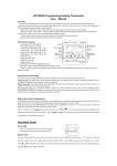
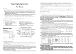
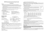
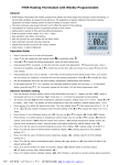
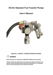
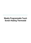
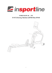
BYC08HE Programming Heating Thermostat
User Manual
[ General ]
This thermostat is applicable to water system and electric-heated system with high power. According to the preset temperature value,
thermostat will automatically start or stop the controlled object (such as valve, heating floor, heating wall, electric heater etc). It will enable you to
live in an energy-saving and comfortable living environment.
• With the latest single-chip computer control technology, the heating equipment is anti-jamming and extremely stable.
• Multiple time modes: 5+2/6+1/7days, the heating equipment supports different temperature setting accordingly with 6 time-modes daily.
Users are free to choose manual mode or full automatic mode for different purposes.
• The clock would continue to run even if power was cut off and it will not affect the period setting value.
• Keypad locking function is designed to prevent the children from misusing.
[Technical parameters]
Manual mode
• Power Supply: 85-250VAC 50/60 Hz
Auto model
Air temperture
Heating
Floor temperture
•The maximum switch power: 2A/16A
• Internal sensor measurement range: 0 - 40ć.
Measured values
Setting range: 5 - 35ć (factory settings: 25ć)
Stage
Week
• External sensor measurement range: 0 - 95ć.
Setting range: 0 - 90ć (factory settings: 50ć)
Seconds
Value for
Week or Stage
• Monitor type: LCD
Settings values
System clock
Down
Clock
• Display area: 60 x 32 mm
Up
Menu
• Setting Unit: 0.5ć/step
• Display resolution: 0.1ć
Power On/Off
•Inside sensor: NTC B=3380 10k @25degrees Clsius
• Extra sensor: NTC B=3380 10k @25 degrees Clsius, length=3 meters
• When the working temperature of thermostat is below 0 degrees or thermostat’s detected temperature is below 0 degrees, screen would
display as 0 degrees.
[Temperature control mode]
According to the sensor setting of thermostat, there are three different control modes, enter the advance function to set.
Internal control (IN): Only enable built-in sensor temperature measurement, the temperature control is based on the built-in temperature sensor. It
is suitable for the detection of air temperature or the room temperature.
External control (OUT): Only enable external sensor to temperature measurement, the temperature control is based on the external sensor. It is
suitable for the detection of the heating body temperature.
Dual temperature control (ALL): Temperature control is based on the built-in temperature sensor and an external temperature sensor
(over-temperature protection). It is suitable for the detection of room temperature and heating body whether over-temperature monitoring. If the
external sensor is over temperature, thermostat will shuts down the heater.
[Display three kinds of temperature]
The thermostat’s main screen shows air temperature or room temperature when it is under IN or ALL temperature controlling mode, The AIR icon
would be lit, the vice-monitor would alternatively display temperature value and current time every 5 seconds.
When the thermostat is under OUT temperature controlling mode, the FLOOR icon would be lit,, the main screen would
display floor
temperature or the tested temperature of the external sensor location.
When the temperature is under ALL temperature controlling mode, press
and
the main screen would display floor temperature or the
tested temperature of the external sensor location. And the FLOOR icon would be lit. The main screen will automatically display air temperature
5 seconds later. Then the AIR icon would be lit.
Operation Guide
[On and off]
Press
keys you can turn on or turn off the thermostat.
The display would be as the left picture when turning off:
[System time]
You need to adjust system time when it comes to use at the first time.How to set the system time: Keep pressing
into the time setting. The current revisable object will flash and display. Press
press
can press
or
and choose time you want to revise (week / hour / minute),
to modify the current setting. If you need to modify the previous parameters, please press
to exit the system clock settings.
for 5 secondsˈit will enter
key. After modified minute,you
[Automatic / manual switch]
Press
you can choose the manual mode or automatic mode.
Manual mode: System will control temperature under the set value without any change. The set temperature is going to be the most comfortable
temperature. There would be no icon
or week/ Stage displaying.
Automatic mode: System would control temperature according to the preset temperature values in different time. The icon
will lit, which
means that the system is running under automatic mode. The week and Stage icon would alternately display every 5 seconds, 1-7 is
systematic reuse. When screen shows WEEK, 1-7 would display the values of the week. When screen shows STAGE, 1-6 would display the
current values.
[Setting the periods of time modes]
The periods setting can realize the control of temperature and time under automatic mode. Once setting up, the values could be saved and
reused in the thermostat forever.
The thermostat can save three kinds of schedules (5+2 / 6+1 / 7) in 6 periods; One week for a cycle.
Each data is saved as the start time (hours: minutes) and the temperature degree of this period. The end time of the period would be saved as the
start time of next period. You can also shut down a certain period according to your actual needs.
Press the
for 5 seconds, you will enter into the period setting (See the right picture following).
Press button
to select the object you want to modify (the period start time: hours, minutes and
set temperature), press
or
to modify the corresponding value. If you want to turn off a period,
until the OFF option shows. You can use the
please press
to back to the previous setting.
The system’s default period is 5+2. For specific data, please see the following table. User can modify the period by entering into the programming
interface:
5+2 mode
Monday to Friday
Saturday to Sunday
ID
P1
P2
P3
P4
P5
P6
Start time
06:00
08:00
11:30
12:30
17:00
22:00
Set value
22ć
15ć
15ć
15ć
22ć
15ć
Start time
06:00
08:00
11:30
12:30
17:00
22:00
Set value
22ć
15ć
15ć
15ć
22ć
15ć
For example:When the system time is Friday 08:20 under automatic mode, display would show as: STAGE 2 and the setting temperature value
would be 15 degrees.
[Lock ]
Press key
for 2 seconds at the same time, the controller keypad would be locked. Screen would show
Press the
at the same time for 2 seconds under the locked status, keypad would be unlocked.
.
[System setting]
Warning: System setting is used to set some important parameters of the system, that’s only for professionals’
operation. Do not make any improper modification by yourself. The item has already been debugged and tested by
professionals, there is no need to reset.
Enter the system setting: Press
to switch on the thermostat when the unit is turned off. Within the next second please press Key
as
soon, you will enter into system setting.
The system menu parameters in order of appearance: AdJ->PrG->LtP->SEn->Top->dt0->dt1->bL->Sat->dEFˈ
The thermostat’s monitors displaying type is LCD segment displaying. There are some differences between the displayed value and practical
value.
Please make reference to the specific figure:
You can press
press the
to switch the system parameters. At the same time press
or
or
to modify settings. Select a set value. If you do not
, the parameters would not be modified. If you want to save the data, you must go through all the functions then exit the
system menu.
Display
AdJ
Set the content
Adjustment range
The default value
temperature correction
-5ć ~ 5ć
-2.5ć
Used to correct the sensor value, screen would show the value needed to be revised when adjusting; the revised
value will be displayed after 3 seconds.
PrG
The period-time mode
5+2 / 6+1 / 7
5+2
5+2˖Monday to Friday is set as the same; Saturday to Sunday is set as the same.
6+1˖Monday to Saturday is set as the same. Sunday is individually controlled.
7˖Monday to Sunday is set as the same.
Antifreeze
LtP
On: Enable
/ OFF: Disable
Low temperature protection, what is suitable for the water system
OFF
To prevent the pipe from freezing at low
temperature.
IN: Built-in
Sensor or temperature control mode
Sen
IN˖internal control, room sensor
OUT: External
ALL:Dual temperature control
Out˖external control, floor sensor
IN
ALL˖double temperature double
control, the internal room temperature sensor, external sensor overheating protecting
External temperature sensor limit
tOP
40-80ć
50ć
The sensor is set to ALL, the temperature limit external sensor value
Internal sensor hysteresis
dt0
0.5-4ć
1ć
0.5-5ć
3ć
Built-in temperature sensor hysteresis
External sensor hysteresis
dt1
External temperature sensor hysteresis
Backlighting status
bL
On: Always on
OFF˖Auto turn off after 5sec
OFF
Backlight lighting mode, can be set according to personal preference
Status at re-power
Sat
OFF: off status at every time
On: the same as previous,
OFF
Used to control the power state of the boot
Restore factory settings
deF
Restore factory settings
To restore the default settings
[ The common errors and solutions of the system ]
1. Fault phenomenon : There is no display
Reason & solution:
1ǃPower supply system is having problems or power is supplied incorrectly, please check if the inlet wire is normal.
2ǃIf the connection is not right, please wired up as the wiring diagram on the back side.
3ǃActual temperature is too low, please note the thermostat temperature range. If the temperature is lower than -5 ć, the unit cannot
normally display.
4ǃPower supply box and the motherboard Coupling is not connected correctly, please connect correctly.
5ǃPower supply box and the motherboard Coupling are opposite inserted, please mind the direction
6ǃPower supply box and the motherboard Coupling is broken, please don't overexert. Coupling length is 6cm, the installation must be
careful. If damaged, no warranty and replacement
2. Fault phenomenon :
Reason solution:
3. Fault phenomenon :
Reason solution:
Display rupture
Display encounters hard objects or sudden force, no replacement and warranty
Display a black screen
If the display surface temperature is too high, please note whether there is heater nearby,
4. Fault phenomenon :
if so please remove.
Display ER0 or ER1
Reason solution:
ER0˖If built-in sensor is abnormal, please pay attention to whether the small black dot in temperature sensing window was damaged during
removal
ER1˖The system is set in the dual temperature control (ALL) mode, or it is not connected with an external sensor, or the external sensor is
abnormal.
5. Fault phenomenon :
Reason solution:
6. Fault phenomenon :
Reason solution:
Reason solution:
Backlight always bright
1ǃThe ON is set in the system menu bL
8. Fault phenomenon :
2ǃIf it is damaged, please replace it.
Large deviation of measurement temperature and the actual temperature
1ǃThe thermostat should be installed at ventilated place. It can not be installed at the place in direct sunshine or nearby the
2ǃBack connection screw is not locked, causing terminal serious fever
9. Fault phenomenon :
Reason solution:
Display 0 degrees
It is normal if thermostat display 0 degrees when the actual environment is below 0 degrees.
[ Dimension in mm ]
[ Wiring diagram ]
ac in:85-250v
Imax 2A
ac in:85-250v
Imax 16A
H1 WIRE DIGRAM
N
H3 WIRE DIGRAM
Relay2
To boiler
SPST.
ac in
L
VALVE
Relay1
N1
extra sensor
N
ac in
heater
No backlight
Please check whether backlight lamp connection is broken when removing in the panel.
7. Fault phenomenon :
Reason solution:
No pen on LCD
Please check whether the iron plate is deformation when installation. If it is deformation, please correct it.
L
LOAD
L1
extra sensor
[ Installation Diagram ]
1. Separate a box to start the installation
2. Using a screwdriver and gently pry the position as shown,
separate panel and the iron plate
2
3. Separate coupler; please note the direction of lead,
4. After the panel is separated, please pay attention to the
interior components of the panel, handled
3
4
1
with care and properly placed!
5. Strip length <= 9MM
Wiring up as picture, you must tighten the
terminal screws, the iron plate
screws can not be too tight to prevent iron plate to deformation
5. Plug in the join line, fasten the panel .Buckle panel, align this position
6. Close frame, the installation is complete
6
5