1
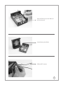
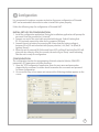
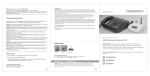
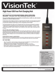
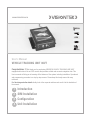
www.visiontek.co.in
GPRS
GPS
Triband GSM
User’s Manual
VEHICLE TRACKING UNIT 86VT
Congratulations !!! We thank you for purchasing VISIONTEK VEHICLE TRACKING UNIT 86VT
equipped with state of the art GPS receiver that provides reliable and accurate navigation data. This
User's manual will help you in knowing all the features of the system including installation. Operational
and programming procedure in a step by step manner. Please keep this handy manual for easy
reference.
For Servicing and other details kindly look at the corporate address and email id at the backside of
the manual.
1 Introduction
2 SIM Installation
3 Configuration
4 Unit Installation
1 Introduction
Visiontek Vehicle Tracking Unit 86VT, equipped with state of the art GPS receiver provides
reliable and accurate navigation data. The unit enables the vehicle owners or third parties to
track the location of a Truck, Ship, Container, Car or any object which is moving.
All the communication with the user/server is handled by Tri-Band GSM/GPRS module which
accurately delivers all the navigation date. The communication is either through Short
Message Service (SMS) or GPRS network.
The Visiontek 86VT is provided with a RS-232 port for configuration of the unit.The unit can be
also remotely configured (OTA Configuration). In addition the unit is provided with two
switches (One for Voice & One for SMS) for communicating with pre-defined numbers. A voice
port is provided for two way communication and buzzer is provided for incoming calls alert.
The unit can be configured to receive the incoming calls from pre-defined numbers.
FEATURES:
n
Tri-band 900/1800/1900 MHz GSM/Gprs Module
n
20 Channels GPS receiver (SiRF III)
n
RS232 Serial Port
n
Built-in battery
n
Ignition ON/OFF detection
n
Wide DC input voltage range (10.5V-30V)
n
Local & Remote Configuration
n
SMS / GPRS Communication
n
Support TCP & UDP
n
Real Time Clock (RTC)
n
On-Line and Off-Line tracking.
n
LED indication for GSM, GPS and Power status
n
Switch for voice & SMS communication
n
Buzzer for incoming calls indication
n
Configure upto 5 incoming call numbers
n
GSM + GPS Combo antenna
2 SIM Installation
1. The Visiontek 86VT unit can be easily opened by removing the four screws connected as
shown in the figure. Make sure that the power cable is not connected to the power source
NOTE : PIN Code of the SIM Card must be DISABLED
1
Open the SIM tray, Insert the SIM card
and close the tray
Internal battery installation
GSM and GPS antenna
2
3 Configuration
It is recommend to involve a computer technician for proper configuration of Visiontek
86VT and an automobile electrician in order to install the system properly.
Follow the following steps for configuration of Visiontek 86VT.
INITIAL SET UP FOR CONFIGURATION:
1. Install the configuration application. During the installation, application will prompt for
password. Enter the password as “visiontek”.
2. Connect one end of the serial cable provided with the unit. Vehicle Tracking Unit
RS-232 port and connect the other end to computer COM port.
3. Connect the unit to battery for powering ON. Ensure that the battery voltage is
between 9V to 30V and connected with proper polarities (+Ve (Red) –Ve (Black) &
Ignition (Green)).
4. When the unit is powered ON, Yellow and Green LED's will be off and only Red LED will
glow with low intensity. After few seconds, the unit will give “Beep” sound indicating
that the unit is ready for configuration.
CONFIGURATION:
The configuration involves the programming of details related to Vehicle, GSM/GPRS
parameters, GPS parameters and other functions.
1. Open the “VTU Configuration” application. Enter the user name and password as
required by the customer. Customer should remember the user name and password
for future configuration.
2. On successful entry of user name and password, the following window appears on the
screen.
3
3. Select comport to be used for the configuration from the drop down menu and press
“connect”.
4. Following options are provided in configuration application.
1. Priority.
2. Connection Information.
3. Service Information.
4. SMS Message.
5. Incoming Numbers.
6. Send.
7. Clear Data.
8. Details From VTU.
9. Configuration History with Delete, Export, Find & Delete All options.
4.1 PRIORITY: Customer can select the communication mode from VTU to the remote
server location.
SMS:
n
Select “SMS” to send the data using the Short Message Service function.
n
When “SMS” option is selected, the unit will send the data to the remote server only
through the “SMS” function.
n
When selected, all the programmable parameters related to GPRS like IP Address, Port
Address, APN, User Name and Password will be disabled.
GPRS:
n
Select “GPRS” to send the data using the General Packet Radio System.
n
When “GPRS” is not available from the network, the unit will store all the GPS data.
When the unit enters to GPRS network, all the stored data will be send to remote server.
OFFLINE
Select offline to make unit work without GSM.
n
n
When offline option is selected, the unit will store all the GPS data received as per the
frequency defined.
n
The stored data can be retreieved with the help of offline details option provided.
4.2 CONNECTION INFORMATION: The following details to be provided for making
the data transfer from the unit to remote server by GPRS call.
Protocol
Select the protocol to be used making communication both
both TCP/IP and UDP.
Primary Port :
Enter the Primary Port of remote server.
Primary IP :
Enter the Primary IP number of the remote server to which
the data to be sent.
Secondary Port:
Enter the Secondary Port of remote server.
Secondary IP :
Enter the alternate port for send data when primary
IP is not available.
APN:
Enter the APN for connecting to the GPRS network.
User Name:
Enter the User Name (If any) for the GPRS connection.
Password:
Enter the Password (If any) for the GPRS connection.
NOTE : Enter default user name as ‘user’ and also default password as ‘user’
4
4.3 SERVICE INFORMATION:
Vehicle ID:
Enter the Vehicle ID to which the unit is connected.
Server Number:
Enter the server number (Mobile Number) to which the data
to be sent when “SMS” communication mode is selected.
Voice Number:
Enter the number to which voice communication is required.
This number will be activated when the switch on the unit
is pressed.
SMS Number:
Enter the number to which SMS to be sent when
switch is pressed. Pre-defined message will be sent.
GPS Frequency:
Enter the time duration for which the unit should read the
GPS parameters. The time can be from 001 seconds to 255
seconds.
GSM Frequency:
Enter the time duration for which the unit should send the
received data to the remote server. The time duration entered
here will be applicable for both “SMS” and “GPRS”.
GMT Time Offset:
Select the country GMT time difference. In case of India it is
+0530.
OTA:
Select the check box when configuring the remote unit.
Uncheck the box when configuring the unit locally by
connecting to PC.
Remote Number :
Enter the SIM number of the remote unit. The OTA message
will be send to the number entered.
NOTE : Remote number will work only when external modem is connected to PC.
4.4 SMS MESSAGE:
n
Enter the pre-defined message content to be sent when the
switch is pressed.
4.5 INCOMING NUMBERS:
n
Enter the incoming numbers to be allowed. Any number received by the unit other than
the entered numbers will not be allowed.
n
A maximum of 05 numbers can be entered.
4.6 Send:
n
Select the send option to store all the configured parameters in to the unit.
4.7 Clear Date:
n
Select the option to clear all the parameters displayed on the screen.
4.8 Details from VTU:
n
Select the option to read configuration details stored in VTU.
4.9 GPS Details:
n
User can select the GPS parameters in the required format.
4.10 Offline Details:
n
The location details stored in the unit can be retrieved with this function.
4.8 Configuration History:
n
When “Send” option is selected, all the parameters configured will be stored into the
unit and the same are stored in the configuration history.
n
Customer can recall the configuration history as and when required for review. The
application will store approximately 1000 configurations.
5
4.9 Edit:
n
Select any configuration details from the history and select “Edit” to edit the details. The
edited details can be stored in to the unit.
4.10 Export:
n
Select the function to Export the configuration history details.
4.11 Find:
n
Select the function to find the configuration details of a particular vehicle from the
history.
4.12 Delete All:
n
Select to delete the configuration history details.
4.13 Close:
n
Select to close the application.
NOTE: After completion of the configuration, switch OFF & ON the VTU.
3 Unit Installation
1. Initial Setup for Installation: Select the location where the unit to be fixed /
installed. Connect the GSM antenna to the GSM connector provided on the unit. Connect
the GPS antenna to the GPS connector provided on the unit. GSM & GPS marking is
provided near to the connectors for easy identification.
For good GPS coverage, make sure that the GPS antenna has a clear view at the sky
preferably outdoors. Ensure that the top of the antenna is aimed at the open sky.
2. Power Connection: Connect the unit to DC power source/battery for Power ON.
Ensure that the input voltage to the unit is between 9V DC to 30V DC.
Connect the ignition wire to the ignition ON/OFF switch.
When the units is powered ON, all the three LED's (Red, Yellow and Green) related to
power, GSM and GPS will glow continuously.
3. LED Indications
LED
Status
Red
Unit Power ON
Flashing
Yellow
Searching for GPS
GPS Not available.
Green
GSM Network available.
Searching for the GSM
Note: The LED will flash at
network.
GSM Network not available. higher speed when sending
data to remote server.
GPS Fix available
NOTE: When the unit is in programming mode, Yellow and Green LED's will not
glow and only Red LED will glow with low intensity.
6
WARRANTY
VISIONTEK 86VT, Vehicle Tracking Unit is warranted for a period of 12 months from the date of sale against
manufacturing defects. GSM, GPS antennas and Battery are warranted for six months against
manufacturing defects. Linkwell Telesystems Pvt. Ltd., obligation under this warranty shall be limited to
servicing or replacing the defective parts provided that notice of such defects and satisfactory proof
thereof is given to Linkwell Telesystems Pvt. Ltd.
The warranty does not cover any defect in the product caused by accident, misuse, mishandling,
negligence, alteration, modification or substitution of any of the components or parts or any attempt at
internal adjustments, any form of tampering by unauthorized/unskilled service personnel, loss of
components or accessories, natural calamities and over voltage of electricity.
Under no circumstance shall Linkwell Telesystems Pvt. Ltd., be liable for any consequential or resulting
injury or for loss, damage or expenses directly or indirectly arising from the use of this product Linkwell
Telesystems Pvt. Ltd. will make every effort to carry out repairs/replacement under this warranty as early as
possible and it is expressly made clear that the company shall not be liable to do so within any specified
time or period.
The decision of Linkwell Telesystems Pvt. Ltd. as to the nature of the defect and applicability of this
warranty shall be final. Claims if any, to this warranty shall be only made before the courts having
jurisdiction in Secunderabad, Andhra Pradesh, INDIA.
Product Pictures
LED Indicators
Connectors
Linkwell Telesystems Pvt. Ltd.
Gowra Klassic, 1-11-252/1/A, Begumpet, Hyderabad - 500 016. Andhra Pradesh, INDIA.
Ph. : +91-40-66388000 | Fax : +91-40-66388006, 27763838
BRANCHES: NOIDA - 0120-2549090, 2549095, 2541427, 2541437 | KOLKATTA - 033-22176549, 22169301 |
AHMEDABAD - 079-40062001, 40062002 | MUMBAI - 022-24916940, 24916942 | VIZAG - 0891-2550725,
2564752,2508088 | BANGALORE - 080-25598811, 25550729, 25591457 | CHENNAI - 044-24797950, 24797960
| KERALA - 94471-37717
7