1
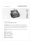
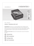
Step-5: Display shows “LOCAL NUMBER DELETE”.
Press # key to delete the area code entered. Press * key for next menu.
Step-6: Display shows “QUIT PROGRAMMING”. Press # key to quit the programming. Press
* key to go back to first menu.
Programming Mode 2
In normal mode, the LCD display shows VISIONTEK. On lifting the handset, display shows
“PLEASE DIAL”. Press ** and enter the password. Default password is 9876.
Step-1: On successful entry of password, LCD shows “CHECK SIGNAL QUALITY”. Press # key
to display the signal level in db. Press * key for next menu.
Step-2: Display shows “TOLL CODE ENTRY”. Press # key to enter Toll Free codes i.e. the codes
for which polarity reversal is not required. Provision is given for entering 20 numbers. Press
* key for next menu.
Step-3: Display shows “TOLL CODE REVIEW”. Press # key to review the Toll Free codes
entered. Press * key for next menu.
Step-4: Display shows “TOLL CODE DELETE”. Press # key to delete the Toll Free codes
entered. Press * key for next menu.
Step-5: Display shows “RESET CODE ENTRY”. Press # key for entering new codes. After entry,
Press # key for entering pulse rate. Fifteen codes and corresponding pulse rates can be
entered.
Step-6: Display shows “RESET CODE REVIEW”. Press # key to review codes and pulse rate
entered. Press key for next menu.
Step-7: Display shows “RESET CODE DELETE”. Press # key to delete the codes and pulse
rates entered. Press key for next menu.
Step-8: Display shows “QUIT PROGRAMMING”. Press # key to quit the programming. Press
key to go back to first menu.
WARRANTY
VISIONTEK FCT 81GF is warranted for a period of 12 months from the date of sale against manufacturing
defects. Linkwell Telesystems Pvt. Limited, obligation under this warranty shall be limited to servicing or
replacing the defective parts provided that notice of such defects and satisfactory proof thereof is given to
Linkwell Telesystems Pvt. Limited.
www.visiontek.co.in
The warranty does not cover any defect in the product caused by accident, misuse, mishandling,
negligence, alteration, modification or substitution of any of the components or parts or any attempt at
internal adjustments, any form of tampering by unauthorized/unskilled service personnel, loss of
components or accessories, natural calamities and over voltage of electricity.
Under no circumstance shall Linkwell Telesystems Pvt. Limited, be liable for any consequential or resulting
injury or for loss, damage or expenses directly or indirectly arising from the use of this product Linkwell
Telesystems Pvt. Limited will make every effort to carry out repairs/replacement under this warranty as
early as possible and it is expressly made clear that the company shall not be liable to do so within any
specified time or period.
The decision of Linkwell Telesystems Pvt. Limited as to the nature of the defect and applicability of this
warranty shall be final.
Claims if any, to this warranty shall be only made before the courts having jurisdiction in Secunderabad,
Andhra Pradesh.
User’s Manual UM-0016 Rev.1.0
GSM Fixed Cellular Terminal 81GF
Product Pictures
Congratulations !!! We thank you for purchasing the VISIONTEK 81GF GSM Fixed Cellular
Terminal with Fax a single line simulation with GSM Network. This User's manual will help you in
knowing all the features of the system including installation. Operational and programming procedure
in a step by step manner. Please keep this handy manual for easy reference.
Wall Mount
Table Top
For Servicing and other details kindly look at the corporate address and email id at the backside of
RS-232 Port
the manual.
PRECAUTIONS:
1. Do not remove or insert the SIM card when the unit is powered ON.
2. Do not bend or roll the ANTENNA cable.
3. Whenever Battery voltage is discharged to 10.8volts, on console display “Battery low
message” is displayed, for safe mode switch off the unit.
Linkwell Telesystems Pvt. Ltd.
Gowra Klassic, 1-11-252/1/A, Begumpet, Hyderabad - 500 016. Andhra Pradesh, INDIA.
Ph. : +91-40-66388000 | Fax : +91-40-66388006, 27763838
1 Introduction
2 Installation
3 Operation
BRANCHES: NOIDA - 0120-2549090, 2549095, 2541427, 2541437 | KOLKATTA - 033-22176549, 22169301 |
AHMEDABAD - 079-40062001, 40062002 | MUMBAI - 022-24916940, 24916942 | VIZAG - 0891-2550725,
2564752,2508088 | BANGALORE - 080-25598811, 25550729, 25591457 | CHENNAI - 044-24797950, 24797960
| KERALA - 94471-37717
TECHNICAL SPECIFICATIONS :
Technology : Advanced microcontroller based.
Display : 16X1 Alphanumeric display
4
5
1 Introduction
VISIONTEK GSM Fixed Cellular Terminal 81GF (FCT) with G3 Fax connectivity is a single line
PSTN simulation made available from GSM /GPRS network. This gadget performs the task of
converting GSM calls to normal analog telephone line with an output similar to existing
PSTN environment with all the basic features and additional G3 Fax feature. It provides
access to home, office, or any remote location where phone and fax service is needed and
GSM footprint is available. Primary telephone fax service, extra lines and security backup are
made available thus facilitating outgoing voice and fax calls anytime and anywhere.
VISIONTEK FCT package consists of the following:
n
GSM FCT – 1 No.
n
Antenna – 1 No.
n
Line Cord – 2 No.
n
Power Adaptor – 1 No.
n
RS-232 Serial cable.
n
User Manual – 1 No.
2 Installation
SIM Card Installation:
The FCT requires a SIM (Subscriber Identification Module) for its normal operation. SIM
socket is provided on the bottom side of the unit.
1. Disconnect power supply if it is already connected to the power socket.
2. Remove the SIM card window by removing the screw.
3. Open the SIM card holder.
4. Ensure for proper direction of the SIM card and insert it gently into the SIM card holder.
5. Close the SIM card holder and press the SIM card holder in forward direction for locking.
6. Fix the SIM card window with the screw.
Antenna Installation:
1. Antenna connector is provided at the rear side of the unit.
2. Connect the antenna supplied with the unit to the connector and ensure for proper
contact.
Power Connection:
1. Plug in the primary of adaptor into 230V AC power socket and the secondary to the
Power socket (DC 14.2/3A) provided at the rear side of the unit.
2. Connect the battery cable of the Unit to the external battery (12V/5AH). Battery socket
is provided at the rear side of the unit. Ensure for proper polarity.
3. Switch ON the unit and observe for the following LED indications on the front panel.
- Red LED indicates the presence of AC power.
- Green LED indicates the presence of Network. LED Blinking indicates the availability of
network.
1
SENDING FAX MESSAGES:
1. Insert the document into the document feeder.
2. Pick up the handset or press the hands free key on the fax machine.
3. Dial the number of the receiving machine.
4. Wait for the connection. Depending on the setting of the receiving machine, a facsimile
reception tone will be heard.
5. Once the fax machine is connected, the fax machine will automatically transmit the
document.
Phone Connection
1. Connect the telephone at the RJ11 socket (PHONE) provided at the rear side of the unit.
2. Lift the handset and hear for the dial tone.
FAX CONNECTION:
1. Connect the fax at the RJ11 socket (FAX) provided at the rear side of the unit.
2. Lift the fax handset and hear for the dial tone.
3 Operation
RECEIVING FAX MESSAGES:
1. The fax machine will automatically answer the incoming calls.
2. If the fax machine detects fax tones, it begins to receive faxes automatically.
Making Calls
1. Lift the handset and hear for the dial tone.
2. Dial the phone number. The dialed number is displayed on the LCD display.
3. After finishing dialing, Press # key on the telephone instrument to send the dialed
number. This will avoid the wait time of 7 seconds. Call progressive tone will be heard in
receiver till call gets connected.
NOTE: (1) For additional information, kindly refer to the user guide of the fax machine.
(2) Use * key to scroll the menus, # to confirm and go On-hook to skip the
programming,
Receiving Calls
1. The telephone will give a ring on receiving the incoming call.
2. Receiver number is displayed on the LCD display **.
3. Pick up the handset to answer the call.
** Subject to network support
SENDING AND RECEIVING FAX MESSAGES:
The VISIONTEK 81GF FCT terminal allows the connection of group3 fax in the similar way as
telephone instrument.
NOTE: (1) The fax communications service has to be activated by the network
operator. Otherwise the network will not allow faxes to be sent or received.
Programming Mode 1
1. In normal mode, the LCD display shows VISIONTEK. On lifting the handset, display shows
“PLEASE DIAL”.
2. Press ** and enter the password. Default password is 9999.
Step-1: On successful entry of password, LCD shows “CHANGE PASSWORD”. Press # key to
change the default password or Press * for next menu.
(2) You will not be able to make or receive the other voice calls while a fax
communications is established.
Step-2: Display shows “ERASE MEMORY”. Press # key to erase the memory. Press key for
next menu.
Step-3: Display shows “LOCAL NUM YES”. Press # key to enter the area code to avoid dialing
the area code for local calls. Press * key for next menu.
1. The FCT is programmed to automatically detect the out going calls made by FAX
machine. This means the user simply has to use the fax in a same way as a conventional
telephone line
2. Incoming faxes are received in the same way as using the fixed line.
Step-4: Display shows “LOCAL NUMBER REVIEW”.
Press # key to review the area code entered. Press * key for next menu.
2
3