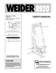
1
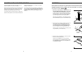
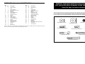
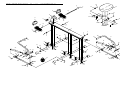
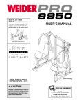
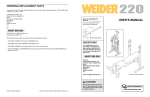
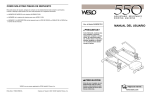
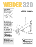
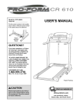
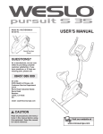
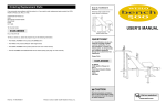
ORDERING REPLACEMENT PARTS
If you encounter any difficulties with this product, or if you need to order replacement parts, please call or write
the ICON Health & Fitness, Ltd. office.
®
ICON Health & Fitness, Ltd.
Unit 4
Revie Road Industrial Estate
Revie Road
Beeston
Leeds, LS118JG
UK
Model No. WLEMRW17910
Tel: Country Code:
08457 089 009
USER’S MANUAL
QUESTIONS?
Outside the UK: 0 (044) 113 387 7133
Fax: 0 (044) 113-387 7125
When calling or writing, please provide the following information:
• The MODEL NUMBER of the product (WLEMRW17910)
• The NAME of the product (WESLO® 550 adjustable resistance rowing machine)
• The KEY NUMBER and DESCRIPTION of the part(s) (see the PART LIST and EXPLODED DRAWING
attached at the centre of this manual).
As a manufacturer, we are committed to providing complete
customer satisfaction. If you
have questions, or if there are
missing or damaged parts,
please call:
08457 089 009
Or write:
ICON Health & Fitness, Ltd.
Unit 4
Revie Road Industrial Estate
Revie Road
Beeston
Leeds, LS11 8JG
UK
email:
[email protected]
CAUTION
Read all precautions and instructions in this manual before using
this equipment. Save this manual
for future reference.
Part No. 178030 R0801A
Printed in Taiwan © 2001 ICON Health & Fitness, Inc.
Visit our website at
www.weslo.com
OPERATING THE ROWING MACHINE
BEFORE YOU BEGIN
Thank you for selecting the WESLO® 550 adjustable
resistance rowing machine. Rowing is one of the most
effective exercises known for toning the body,
strengthening the muscles, and building the cardiovascular system. The WESLO 550 is designed to let you
enjoy this effective exercise in the convenience and
privacy of your home.
For your benefit, read this manual carefully before
you use the WESLO 550. If you have additional questions, please call our Customer Service Department at
08457 089 009.
To help us assist you, please note the product model
number before calling. The model number is
WLEMRW17910.
HOW TO OPERATE THE MONITOR
PROPER ROWING FORM
To turn on the power, press the monitor button.
Sit on the seat, facing the footrests. Place your feet in
the footrests and adjust the straps to fit your feet.
Hold the handles of the rowing arms with an overhand
grip. Correct rowing form consists of three phases:
To switch modes, press the button until the desired
mode is displayed (black triangles mark the selected
modes). The monitor features the following modes:
1. The first phase is the CATCH. Slide the seat forward until your knees are almost touching your
chest. Pivot the rowing arms forward until your
hands are close to your feet.
• SCAN—The monitor displays the time and calorie
modes, switching every five seconds.
• COUNT (CNT)—The monitor displays the number of
repetitions you have completed, up to 9,999.
2. The second phase is the DRIVE. Push backward
using your legs. Keep your back straight. Lean back
slightly at the hips (not at the waist) and begin
pulling the rowing arms toward your chest. Keep
your elbows outward.
• TIMER (TMR)—The monitor counts the time, beginning when you start exercising (up to 99 minutes).
After 5 seconds of inactivity, the timer pauses.
IMPORTANT PRECAUTIONS
WARNING:
To reduce the risk of serious injury, read the following important precautions
before using the rowing machine.
1. Read all instructions in this manual before
using the rowing machine. Use the rowing
machine only as described.
5. Keep children under 12 and pets away from
the rowing machine at all times.
6. Wear appropriate clothing when exercising.
Always wear athletic shoes for foot protection.
2. It is the responsibility of the owner to ensure
that all users of the rowing machine are adequately informed of all warnings.
• CALORIE (CAL)—The monitor displays the approximate number of calories burned. Note: Use this
mode only for comparison; do not use this mode for
medical purposes.
3. The third phase is the FINISH. Your legs should be
nearly straight. Continue to pull the rowing arms
until your hands are even with your chest.
To reset the monitor, press the button and hold it for
two seconds. The monitor automatically turns off
after five minutes of inactivity.
After the finish phase, extend your arms forward and
pull the seat forward using your legs. Repeat, moving
through all three phases with a smooth, fluid motion.
Remember to breathe normally as you row—never
hold your breath.
HOW TO ADJUST THE RESISTANCE
7. Keep your hands away from moving parts.
3. Use the rowing machine indoors, on a level
surface, away from moisture and dust. Place
a mat under the rowing machine to protect
the floor or carpet.
8. If you experience dizziness or pain at any
time while exercising, stop immediately and
begin cooling down.
9. The rowing machine is intended for in-home
use only. Do not use the rowing machine in a
commercial, rental, or institutional setting.
4. Inspect and properly tighten all parts of the
rowing machine regularly. Replace worn parts
immediately.
WARNING:
Before beginning this or any exercise program, consult your physician. This
is especially important for persons over the age of 35 or persons with pre-existing health problems.
Read all instructions before using. ICON assumes no responsibility for personal injury or property
damage sustained by or through the use of this product.
To vary the
intensity of
Increase
your exerClamp
cise, the
resistance of
Clamp
the rowing
Knob
Decrease
arms can be
changed.
The resistance is
determined
by the positions of the clamps on the rowing arms. To
change the resistance, first loosen the clamp knobs.
To increase the resistance, slide the clamps higher on
the rowing arms; to decrease the resistance, slide the
clamps lower. Tighten the clamp knobs. Refer to the
marks on the rowing arms to make sure that both
clamps are at the same height.
ALTERNATE ROWING
Sit on the rowing machine as described above and
extend your legs until they are nearly straight. Keep
your back straight. Alternately pull the right rowing arm
and then the left rowing arm toward your chest.
SIT-UPS
Sit on the rowing machine as described above. Make
sure that your feet are properly strapped into the
footrests. Bend your knees slightly and clasp your
hands behind your head. Perform as many sit-ups as
desired.
WESLO is a registered trademark of ICON Health & Fitness, Inc.
2
7
MAINTENANCE AND STORAGE TIPS
ASSEMBLY
Inspect and tighten all parts of the rowing machine
regularly. Replace worn parts immediately.
teries. See assembly step 11 on page 5 for battery
installation instructions.
Place all parts of the rowing machine in a cleared area and remove the packing materials. Do not dispose of the
packing materials until assembly is completed. Read each step carefully before beginning.
Wipe the rail and the wheels on the seat bracket regularly to keep them free of dust and dirt. The rowing
machine can be cleaned using a soft cloth and mild
detergent. Keep liquids away from the monitor.
The rowing machine can be stored in a vertical position to conserve space. Store the rowing machine in
a location where children cannot tip it. Remove the
batteries from the monitor when storing the rowing
machine.
ASSEMBLY REQUIRES THE FOLLOWING TOOLS (NOT INCLUDED): An adjustable wrench
and a phillips screwdriver
.
If the monitor does not function properly, replace the
batteries. Most problems are the result of drained bat-
1. Note: As you assemble the rowing machine, use
the PART IDENTIFICATION CHART in the centre
of this manual for help identifying small parts.
1
39
2
Orient the Rail (2) so the Reed Switch Wire (39) is at
the indicated end. Orient one of the Long Stabilizers
(1) so the large holes are on the indicated side.
Attach the Long Stabilizer (1) to the Rail (2) with four
Short Stabilizer Bolts (7) and four Small Washers (22).
22
7
1
22
Large
Hole
7
2. Orient one of the Connector Tubes (32) so the narrow bracket is at the indicated end. Attach the
Connector Tube to the Long Stabilizer (1) with a
Long Stabilizer Bolt (14) and a Small Washer (22).
Do not overtighten the Long Stabilizer Bolt.
2
1
14
22
Attach the other Connector Tube (not shown) to the
Long Stabilizer (1) in the same way.
Narrow
Bracket
3. Slide the other Long Stabilizer (1) onto the ends of
the two Connector Tubes (32).
32
3
32
Attach the Long Stabilizer (1) to the Connector
Tubes (32) with two Long Stabilizer Bolts (14) and
two Small Washers (22). Do not overtighten the
Long Stabilizer Bolts.
22
14
32
1
22
6
3
14
4. Attach the Long Stabilizer (1) to the Rail (2) with four
Short Stabilizer Bolts (7) and four Small Washers (22).
8. Attach the indicated end of a Clamp (20) to the right
Resistance Cylinder (26) with a Cylinder Bolt (25), a
Small Washer (22), and an M8 Nylon Locknut (9).
4
2
1
8
17
26
25
40
Secure the other end of the Clamp (20) to the Right
Rowing Arm (17) with a Clamp Bolt (40), a Small
Washer (22), and a Clamp Knob (21).
20
22
Attach the other Clamp (not shown) to the left
Resistance Cylinder and the Left Rowing Arm (not
shown) in the same way. Make sure that both
Clamps are at the same height.
22
22
7
5. Attach the Short Stabilizer (3) to the Rail (2) with four
Short Stabilizer Bolts (7) and four Small Washers (22).
9
21
22
7
5
9. Remove the two indicated Seat Stops (5).
2
9
4
Slide the Seat (23) onto the Rail (2). Make sure that
the thick edge of the Seat is oriented as shown
and that the Wheels (not shown) under the Seat
are in the grooves in the sides of the Rail.
22
5
23
2
Reattach the two Seat Stops (5) with the Seat Stop
Screws (4).
7
22
3
4
5
Thick Edge
7
6. Orient a Resistance Cylinder (26) as shown. Attach
the Resistance Cylinder to the indicated bracket on
the right Connector Tube (32) with a Cylinder Bolt
(25), a Small Washer (22), and an M8 Nylon Locknut
(9).
10. Slide the Footrest Shaft (13) into the indicated hole in
the Rail (2).
6
10
13
26
Attach the other Resistance Cylinder (not shown) in
the same way.
9
Slide a Plastic Spacer (12) and a Footrest (10) onto
the right end of the Footrest Shaft (13). Secure the
Footrest with a Large Washer (8) and an M8 Nylon
Locknut (9).
25
8
12
32
22
10
Secure the other Footrest (not shown) to the left end
of the Footrest Shaft (13) in the same way.
9
2
7. Orient the Right Rowing Arm (17) as shown. Attach
the Right Rowing Arm to the indicated bracket on the
right Connector Tube (32) with a Rowing Arm Bolt
(28), two Small Washers (22), and an M8 Nylon
Locknut (9). Slide the Rubber Cover (35) down so it
covers the bracket.
11. Insert two 1,5V (“AA”) batteries (not included) into the
Monitor (15). Alkaline batteries are recommended.
Make sure that the batteries are oriented correctly.
7
17
Connect the wire extending from the Monitor (15) to
the Reed Switch Wire (39). Remove the protective
tape from the Fastener Strips (36). Press the Monitor
onto the Fastener Strips; be careful not to pinch the
wires.
35
Attach the Left Rowing Arm (not shown) in the same
way.
15
Wire
39
36
28
32
22
22
9
2
12. Make sure that all parts are properly tightened
before you use the rowing machine. Place a mat
under the rowing machine to protect the floor or carpet.
4
11
5
PART LIST—Model No. WLEMRW17910
Key
No.
Qty.
1
2
3
4
5
6
7
8
9
10
11
12
13
14
15
16
17
18
19
20
21
2
1
1
8
4
2
12
2
8
2
2
2
1
4
1
2
1
1
2
2
2
Description
Long Stabilizer
Rail
Short Stabilizer
Seat Screw/Stop Screw
Seat Stop
Rail Cap
Short Stabilizer Bolt
Large Washer
M8 Nylon Locknut
Footrest
Strap
Plastic Spacer
Footrest Shaft
Long Stabilizer Bolt
Monitor
Rowing Arm Cap
Right Rowing Arm
Left Rowing Arm
Handgrip
Clamp
Clamp Knob
Key
No.
Qty.
22
23
24
25
26
27
28
29
30
31
32
33
34
35
36
37
38
39
40
#
26
1
1
4
2
1
2
2
4
2
2
4
6
2
2
4
4
1
2
1
R1001A
Description
Small Washer
Seat
Seat Bracket
Cylinder Bolt
Resistance Cylinder
Magnet
Rowing Arm Bolt
Rowing Arm Sleeve
Rowing Arm Bushing
Magnet Screw
Connector Tube
Wheel
Endcap
Rubber Cover
Fastener Strip
Seat Nut
Wheel Bolt
Reed Switch/Reed Switch Wire
Clamp Bolt
User’s Manual
REMOVE THIS PART IDENTIFICATION CHART, PART
LIST, AND EXPLODED DRAWING FROM THE MANUAL.
Save this page for future reference.
This chart is provided to help you identify the small parts used in assembly. The number in parenthesis following
each part description refers to the key number of the part. The number after each key number refers to the
quantity needed for assembly. Important: Some parts may have been pre-assembled for shipping purposes. If you cannot find a part in the parts bags, check to see if it has been pre-assembled.
Small Washer (22)–26
M8 Nylon Locknut (9)–8
Large Washer (8)–2
Note: "#" indicates a non-illustrated part. Specifications are subject to change without notice. See the back cover
of this manual for information about ordering replacement parts.
Long Stabilizer Bolt (14)–4
Short Stabilizer Bolt (7)–12
Cylinder Bolt (25)–4
Seat Screw/
Stop Screw (4)–2
Clamp Bolt (40)–2
Rowing Arm Bolt (28)–2
EXPLODED DRAWING—Model No. WLEMRW17910
38
R1001A
8
11
9
33
23
13
37
33
15
38
24
27
39
11
6
38
12
31
10
36
4
37
33
12
5
10
4
38
2
9
4
5
8
4
14
5
34
16
22
19
17
5
16
4
19
6
26
22
20
7
14
18
22
25
34
22
40
25
22
35
30
26
9
22
22
22
21
7
1
7
9
25
40
9
22
34
22
1
30
20
35
29
30
22
28
32
22
22
7
32
9
22
22
14
22
3
34
22
22
9
30
28
21
34
29
25
9
14
22
34
7