1
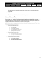
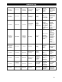
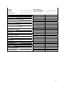
Reverse Osmosis User’s Manual Models Spot Zero™ 4000, 5000, & 7000 Table of Contents Introduction ............................................................................................................................................... 3 Safety ........................................................................................................................................................ 3 Labeling .................................................................................................................................................... 3 System Specifications ............................................................................................................................... 3 Feed Water & Operation Specifications ................................................................................................... 4 Rejection, Recovery, & Flow Rates .......................................................................................................... 4 System Requirements & Operation Guidelines ........................................................................................ 5 Plumbing............................................................................................................................................... 5 Electrical ............................................................................................................................................... 5 Pre-Filtration ......................................................................................................................................... 6 Pump .................................................................................................................................................... 6 Mounting ............................................................................................................................................... 6 Membrane Elements ............................................................................................................................ 6 Start-Up..................................................................................................................................................... 6 Installation ............................................................................................................................................ 7 Start-Up ................................................................................................................................................ 7 Operation & Maintenance ......................................................................................................................... 8 Pre-Filter Pressure Gauges .................................................................................................................. 8 Product (Permeate) Flow Meter & Waste (Concentrate) Flow Meter .................................................. 8 Waste Recycle Valve ........................................................................................................................... 8 Low Pressure Switch ............................................................................................................................ 9 Low Pressure Shut-Off Control Box ..................................................................................................... 9 Auto-Flush ............................................................................................................................................ 9 Pump Bypass Valve ........................................................................................................................... 10 Membrane Removal & Replacement ................................................................................................. 10 Membrane Cleaning ........................................................................................................................... 11 Flushing the System ........................................................................................................................... 16 Draining the System for Shipment...................................................................................................... 16 Troubleshooting ...................................................................................................................................... 16 Low System Pressure ........................................................................................................................ 17 Abnormal Permeate Flow ................................................................................................................... 18 Reverse Osmosis System Troubleshooting ........................................................................................... 18 Operation Log ......................................................................................................................................... 19 Temperature Guide ................................................................................................................................ 20 Service Assistance ................................................................................................................................. 21 Warranty & Guarantee ............................................................................................................................ 21 Notes:...................................................................................................................................................... 23 2 Introduction Your Spot Zero™ commercial reverse osmosis system is a durable piece of equipment which, with proper care, will last for many years. This User’s Manual outlines installation, operating, maintenance, and troubleshooting details vital to the sustained performance of your system. The test results which are included with this User’s Manual indicate your system’s permeate (product) and rejection test results. Your system is designed to operate at a pressure of 150 psi, unless otherwise stated. The recovery set for your system is between 33%-50%. If your system is altered at the site of operation or if the feed water conditions change, please contact your local dealer or distributor to determine the proper recovery for your application. NOTE: In order to maintain warranty, an operating log must be maintained. Copies must be sent to your local dealer or distributor for review. NOTE: Prior to operating or servicing the Spot Zero ™ commercial reverse osmosis system, this User’s Manual must be read and fully understood. Keep it and other associated information for future reference and for new operators or qualified personnel near the system. Safety The Safety section of this User’s Manual outlines the various safety headings used throughout this manual’s text and are enhanced and defined below: NOTE: Indicates statements that provide further information and clarification. CAUTION: Indicates statements that are used to identify conditions or practices that could result in equipment or other property damage. WARNING: Indicates statements that are used to identify conditions or practices that could result in injury or loss of life. FAILURE TO FOLLOW WARNINGS COULD RESULT IN SERIOUS INJURY OR EVEN DEATH. Labeling Do not under any circumstance, remove any Caution, Warning, or other descriptive label from the system. System Specifications Model Design Gallons Per Day Dimensions (approx.) Weight (approx.) Recycle Line Auto Flush Element Size (in.) Elements (qty.) Motor HP Voltage Hertz Spot Zero ™ 4000 Spot Zero ™ 5000 Spot Zero ™ 7000 Vertical 4000 30” x 38” x 47” 235 lbs. Optional Optional 4040 TFC HF-3 2 1 110/220 50/60 Vertical 5000 30” x 38” x 47” 250 lbs. Optional Optional 4040 TFC HF-3 3 1.5 110/220 50/60 Vertical 7000 30” x 38” x 47” 265 lbs. Optional Optional 4040 TFC HF-3 4 1.5 110/220 50/60 3 Feed Connection Product Connection Waste Connection ¾” 1” 1” ¾” 1” 1” ¾” 1” 1” Feed Water & Operation Specifications Nothing has a greater effect on a reverse osmosis system than the feed water quality. For lasting performance it is important to supply the system with the feed water quality shown below. It is also important to feed the system the required amount of feed water. NOTE: It is very important to meet the feed water requirements. Failure to do so will cause the membranes to foul and void the warranty. Hardness Free Chlorine Total Dissolved Solids Turbidity (SDI) pH Iron Silica Feed Water Specifications <1 grain Hydrogen Sulfide 0 ppm Manganese <2000 ppm Organics <5 Temperature 3-11 <0.01 ppm <1 ppm 0 ppm <0.05 ppm <1 ppm 40°F - 80°F 8°C - 27°C Pressure Flow Rate 20 – 60 psi 3 gpm The manufacurer has provided you with operation speicifications. These specifications should be met in order to have the reverse osmosis system perform optimally. All operation specifications are based on the test conditions listed below. Min. Working Pressure Min. NaCl % Rejection Min. Feed (GPM) Max. Hardness Max. TDS Operation Specifications 35 psi Max. Pressure 96% Max. NaCl % Rejection 1.5 Max. Feed (GPM) 15 Grains / Gallon 2000 ppm pH Range Max. Temperature 200 psi 98% 3 3 – 11 105°F Test Conditions: Permeate flow and salt rejection based on 2000 ppm NaCl, 150 psi, 77°F (25°C), pH 7, and recovery as indicated. NOTE: Higher TDS and/or lower temperatures will reduce the system’s production. Rejection, Recovery, & Flow Rates Spot Zero ™ reverse osmosis systems are designed to produce purified water at the capacities indicated by the suffix in the system’s name under the conditions listed above. For example, the Spot Zero ™ 7000 produces 7000 gallons per day of purified water. The amount of total dissolved solids (TDS) rejected by the membrane is expressed as a percentage. For example, a 99% rejection rate means that 99% of total dissolved solids do not pass through the membrane. To calculate the % rejection, use the following formula: % Rejection = (Feed TDS – Product TDS / Feed TDS) x 100 NOTE: All TDS figures must be expressed in the same units, usually parts per million (ppm) or milligrams per liter (mg/l). Spot Zero ™ commercial reverse osmosis systems are designed to reject up to 98% NaCl, unless computer projections have been run and provide a different rejection percentage. 4 The amount of purified water recovered for use is expressed as a percentage recovery. To calculate % recovery, use the following formula: % Recovery = (Product Water Flow Rate / Feed Water Flow Rate) x 100 NOTE: All Flow Rates must be expressed in the same units, usually gallons per minute (gpm). Spot Zero ™ commercial reverse osmosis systems are designed to have a recovery of 33% - 75%, unless computer projections have been run and provide a different recovery percentage. System Requirements & Operation Guidelines Plumbing The membranes and high pressure pumps used on Titan™ systems require a continous and nonturbulent flow of water to the system with a minimum feed pressure of 35 psi, which does not exceed 105°F. The tubing or piping used for the inlet of the concentrate is ¾” NPT. The tubing or piping used for the discharge of the concentrate is 1” NPT and should be run to an open drain in a free and unrestricted manner. The tubing or piping used for the permeate is 1” NPT and can be transported to the holding tank or directly to the point-of-use through a high quality nylon, tubing or PVC pipe, or other FDA accepted materials. Material must not precipitate in the system. Be certain that all of the components of the feed water are soluble at the concentrations attained in the system. A system operating at 33% recovery, concentrates nearly all impuritites 1.5 times. A system operating at a 50% recovery concentrates nearly all impurities 2 times. If the feed water contains a slightly soluble material such as calcium sulfate, silica, or colloidal clay, an anti-scalant should be used. CAUTION: Any restrictions or blockage in the drain can cause backpressure, which will increase the system’s operating pressure. This can result in damage to the system’s components. Electrical The motors used on Spot Zero ™ 4000, 5000, & 7000 systems are pump and motor combinations. They are available in single-phase 110 volt or 220 volt at 60 hertz or 220 volt at 50 hertz at an additional charge. Please ensure that the electrical circuit supplying the system is compatible with the requirments of the specific Spot Zero ™ model. NOTE: We recommend that a licensed electrician install your system in accordance with local and national electrical codes. WARNING: To reduce the risk of electrical shock, the incoming power supply must include a protective earth ground. Each Spot Zero ™ system is equipped with an 5 foot electrical cord. All 110 volt system’s are provied with a 3 prong plug for use in a standard North American household outlet receptacle. All 220 volt 50 hertz models may require the replacement of the standard plug to fit certain receptacles. 5 Pre-Filtration Spot Zero ™ systems are supplied with a polypropylene pre-filter that filters out most particles over 5 microns, a carbon block that removes chlorine, and a polypropylene pre filter that filters out most particles over 1 micron; before the water is pumped through the reverse osmosis membrane. Change the cartridge at least every month or whenever there is a pressure difference of 15% or more between the pressure readings before and after the filter. NOTE: The system must be operated on filtered water only. Do not attempt to clean used filter cartridges. CAUTION: If the pre-filter becomes clogged and the water flow to the pump is reduced or interrupted, cavitation will occur. This will damage the pump. Pump The pumps used on Spot Zero ™ 4000, 5000, & 7000 systems are pump and motor combinations. They are multi-stage centrifugal pumps. Follow these guidelines to ensure proper operation of the pump: The pump must NEVER be run dry. Operating the pump without sufficient feed water will damage the pump. ALWAYS feed the pump with filtered water. The pump is susceptible to damage from sediment and debris. Mounting The free standing system should be bolted down in compliance to local regulation standards. It has a lightweight and portable design for a variety of applications. Membrane Elements Spot Zero ™ reverse osmosis systems come preloaded with Thin Film Composite High Flow membranes. General membrane element performance characteristics are listed below: Min. Working Pressure Min. NaCl % Rejection Min. Feed (GPM) Max. Hardness Max. TDS Membrane Element Characteristics 100 psi Max. Pressure 96% Max. NaCl % Rejection 1.5 Max. Feed (GPM) 15 Grains / Gallon 2000 ppm pH Range Max. Temperature 400 psi 98% 3 3 – 11 105°F Thin Film Composite (TFC) Membranes Test Conditions: Permeate flow and salt rejection based on 2000 ppm NaCl, 150 psi, 77°F (25°C), pH 7, and recovery as indicated. NOTE: Higher TDS and/or lower temperatures will reduce the system’s production. Start-Up Unless otherwise indicated, these instructions cover the Spot Zero ™ 4000, 5000, 7000 reverse osmosis systems. Please refer to the flow diagrams and exploded view diagrams found in this User’s Manual for additional information. 6 Installation The Spot Zero ™ reverse osmosis systems are free standing and require no special installation; however, if placed on an uneven floor, the system may vibrate. If this occurs, place the system on a rubber mat to reduce the vibrations. Carefully inspect your system before start-up. Check all plumbing and electrical connections. Connections may have come loose during shipment. A User’s Manual, Test Results, and Filter Housing Wrench will accompany your Titan™ reverse osmosis system. Start-Up 1. Locate the feed water inlet on the pre-filter housing. 2. Attach a inlet hose to the feed water inlet, or permanently plumb the feed water piping or tubing to the inlet. Always maintain a smooth and sufficient flow of feed water during operation. 3. Locate the permeate outlet. 4. Attach the permeate hose to the permeate outlet. Make sure that the permeate water can flow freely and that there is no backpressure. Backpressure can cause damage to the membrane. CAUTION: The plumbing in the permeate line can contaminate the high quality water produced by the system; ensure that the components are compatible with the application. The pH of the reverse osmosis permeate will normally be 1-2 points lower than the feed water pH. A pH of 6.5 or lower can be very aggressive to some plumbing materials, such as copper piping. 5. Locate the concentrate (waste) outlet. The concentrate outlet is located behind the control panel. Locate the concentrate outlet on the drain side of the concentrate control valve. 6. Attach, the drain line to the concentrate outlet. 7. Run the concentrate line to the drain. Water must be allowed to run freely, without any restrictions or blockage in the drain line. Make sure that no backpressure exists on the concentrate line. 8. Ensure that the electrical power requirements of the Spot Zero ™ system match your electrical power supply. 9. Spot Zero ™ systems are typically controlled with a liquid level switch in a storage tank. The liquid level switch turns the system on when the water level in the tank drops, and off when the tank is full. If your reverse osmosis system is equipped with an electrical control box, the level control is connected to the level control connections in the control box. Do not exceed the level control’s power rating. Liquid level switches can be obtained by your local dealer or distributor. If a liquid level switch is to be used, install it at this time and turn the power to the Spot Zero ™ system on. Otherwise, turn the system on by plugging in the power cord. Allow the system to run for about three to five minutes with the concentrate control valve fully open to purge air from the system. 10. The Spot Zero ™ system’s permeate or product water should be discarded for the first hour of operation. This will flush out any impurities which are in the system. Turn the concentrate control valve until the concentrate pressure gauge indicates a pressure of 50 psi. Flush the system at 50 7 psi for 1 hour to remove the impurities from the system. Check for leaks. All Titan™ reverse osmosis systems are fully tested prior to shipment, but leaks may occur due to shipping. 11. Connect the permeate line to the storage tank or point-of-use application. Make sure that no backpressure exists on the permeate line. 12. Locate the concentrate control valve and the concentrate pressure gauge. 13. Turn the concentrate control valve until the designated permeate flow is acquired. For example a Spot Zero ™ 5000 should be adjusted until it produces about 5000 GPD or 3.47 GPM of permeate or product water. The concentrate pressure will increase as the concentrate control valve is closed. The exact operating pressure may vary depending on the temperature and TDS of your feed water. It may be necessary to re-adjust the system if there is a major change in feed water temperature and/or TDS. GPM = GPD/1440 WARNING: Never exceed the maximum pressure rating of your membrane or pressure vessel. NOTE: The Spot Zero ™ 4000, 5000, & 7000 reverse osmosis systems are equipped with a pump discharge throttle valve. This valve is used to adjust the system to the desired recovery. Feed water enters the system through an automatic shut-off valve. Ensure that the valve opens when the system turns on, allowing water to flow through the system, and close when the system turns off, stopping the water from flowing through the system. This will save water and prevent premature fouling of the reverse osmosis membrane. Operation & Maintenance The reverse osmosis process causes the concentration of impuritites in the concentrate stream to increase. The impurities may precipitate (come out of the solution) when their concentration reaches saturation levels. NOTE: Precipitation can scale or foul membranes and must be prevented. Check your feed water chemistry. Pre-treat the water and/or reduce the system recovery as required. If necessary, consult with your local dealer or distributor. Pre-Filter Pressure Gauges These gauges measure the feed water pressure when it enters and exits the pre-filter housing. A pressure differential of 15% or more on the two pressure readings indicates that the pre-filter needs to be replaced. For example, if the inlet pressure is 40 psi, the filter should be changed when the outlet pressure is 34 psi or below. Product (Permeate) Flow Meter & Waste (Concentrate) Flow Meter These flow meters indicate the flow rates of permeate and concentrate water. The measurements, when added together, also indicate the feed water flow rate, if the system is not equipped with a waste recycle. Waste Recycle Valve This valve allows you to recycle some of the concentrate water back to the feed of the pump. This will increase the recovery of the Spot Zero ™ system. An optional waste recycle flow meter allows you to measure how much concentrate is recycled. The amount of waste water recycled is limited by the TDS of the feed water. The drawback of using concentrate recirculate is an increase of total dissolved solids in 8 the permeate water. CAUTION: Excessive recycling may cause premature fouling or scaling of the membrane elements. Low Pressure Switch The low pressure switch shuts off the system when the feed water pressure drops too low for the system to function properly. This prevents damage to the pump. The system restarts automatically when the pressure is restored. If you notice the pressure fluctuating, and the system cycling off and on repeatedly, turn the system off and ensure that proper feed flow and pressure are available to the system. Low Pressure Shut-Off Control Box This feature consists of an electrical control box with a low pressure protection circuit, level control connections, pre-treat lockout connections, and an on/off switch. The low pressure shut-off switch can be ordered with manual or automatic reset. Auto-Flush The auto-flush option bypasses the concentrate control valve, reducing the concentrate pressure and increasing the flow of feed water across the membrane. The auto-flush removes foulants that may have attached to the surface of the membrane. By removing these foulants before they crystalize on the surface of the membrane, the system can operate longer without cleaning and/or replacing the membrane elements. The following are instances in which the auto-flush should be utilized: 1. When injecting antiscalant chemicals. These chemicals keep scaling ions in solution up to a higher concentration so the ions don’t precipitate, and scale the membrane elements. If the solubility concentration is exceeded, the ions may precipitate and scale the membrane. 2. For feed water with a high scaling potential (hard water) in addition to the auto-flush, pre-treat the water with an antiscalant or a softener. Do not use the automatic fast flush instead of pretreatment. 3. Where minimal maintenance is important, auto-flush can increase the time between membrane cleaning. 4. For high TDS (total dissolved solids) applications where the TDS exceeds 500 ppm, consider installing auto-flush. 5. For high recovery applications (use of a recycle valve), consider using auto-flush. 6. For system that may remain inoperative for long periods of time, auto-flush should be installed. The auto-flush will not operate if the electrical power is removed from the system. The auto-flush feature includes a timer with an adjustable setting that regulates its operation. One setting allows you to set the interval between flushing. The timer is preset at the factory to initiate a 5-minute flush every 24 hours. This is based on the time the system is in operation. In the auto-flush mode the water will flush across the membrane in the same direction as the water flows in normal operation; this is not a backwash flow. NOTE: Some permeate will be produced during the auto-flush; therefore, an overflow for the permeate storage tank is recommended. 9 Pump Bypass Valve This valve is installed as a standard feature on the Titan™ 4000, 5000, & 7000 reverse osmosis systems. It provides an adjustment for pump pressure, which will vary as the required system pressure changes. Note that with a centrifugal pump, the pump flow decreases as the operating pressure increases. Pressure 120 psi 150 psi 180 psi 1 HP 10.5 gpm 8 gpm 4 gpm 1.5 HP 12 gpm 10.5 gpm 8 gpm As the feed water temperature decreases, and/or the feed water TDS increases, the system will require a higher operating pressure to produce the specified permeate flow. A Titan™ system installed in Florida may provide the specified permeate flow of 3.47 gpm at 150 psi; however the same system installed in Maine – much colder feed water – may require 190 psi to produce the same amount of permeate. The system in Florida would have a higher concentrate flow to the drain because of the lower operating pressure, which would result in poor system recovery. % Rejection = (Feed TDS – Product TDS)/(Feed TDS) x 100 Membrane Removal & Replacement Changing membranes in pressure vessels is an easy process if you have the proper information and tools at hand. Please refer to the following instructions when removing and replacing membrane elements: 1. Remove the end caps from the top of the membrane housings. This is done by removing the white Nylon snap ring of the Champ housing or unscrewing the bolts of the PuroTech housing, which holds on the clamp. 2. Remove the membrane bag containing the membrane element from the shipping box. 3. Cut the bag open as close as possible to the seal at the end of the bag, so the bag may be reused if necessary. 4. Remove the membrane element from the bag and remove the black core tube protectors from each end of the membrane. 5. Remove parts from the parts container (if included) and inspect. Make sure that all parts are clean and free from dirt. Examine the brine seal, and permeate tube for nicks or cuts. Replace the O-rings or brine seal if damaged. 6. Flow directions should be observed for installation of each element in each housing. As time progresses, the efficiency of the membrane will be reduced. In general, the salt rejection does not change significantly until two or three years after installation when operated on properly pretreated feed water. The permeate flow rate will begin to decline slightly after one year of operation, but can be extended with diligent flushing and cleaning of the system. A high pH and/or precipitation of hardness can cause premature loss in rejection of membrane elements in the system. To replace the membrane elements: 1. Remove all of the membrane element(s) from the membrane element housings from the top of the housing. Heavy-duty pliers and channel lock pliers may be necessary to pull the old membrane element out of the membrane element housing. 10 2. Install the brine seal side of the membrane elements first. When the housings have a direction of flow from bottom to top, the brine seal should be located on the end of the membrane element at the bottom of the housing. 3. Lubricate the brine seal with a food grade lubricant. 4. At a slight angle insert membrane while slightly rotating element being careful not to tear or flip the brine seal. Re-lube the brine seal if necessary. 5. With a smooth and constant motion, push the membrane element into the housing so that the brine seal enters the housing without coming out of the brine seal groove. A slow twisting motion should be used to insert the membrane element, to ensure that the brine seal stays in place. 6. Re-install the end caps by gently twisting the end cap while pushing it onto the housing. Ensure that you do not pinch or fatigue any O-rings while pushing the end plug on. Push the end plug on until the outer diameter of the plug is flush with the outer diameter of the membrane housing. 7. Insert nylon snap ring until fully seated. Snap ring must be able to be spun in place if fully seated. If you are using a stainless steel housing, Install the clamps halves, and tighten bolts until the clamp halves meet. 8. Reconnect any fittings that may have been disconnected when the membrane element housings were disassembled. 9. To Start-Up the system, refer to Start-Up CAUTION: New or factory cleaned membranes are shipped in a preservative solution. New or cleaned membranes must be flushed for at least 1 hour to remove the preservative from the membrane. Discard all of the permeate and concentrate, which is produced during the flush. Membrane Cleaning Periodic cleaning of the membrane(s) can improve system performance. In normal operation, mineral scale, biological matter, colloidall particles, and organic substances can fould the membranes. WARNING: Cleaning chemicals are dangerous and can cause injury and damage to the environment. Read and comply with all safety and disposal precautions listed on the Materal Safety Data Sheets (MSDS’s). It is the user’s responsibility to comply with all applicable federal, state, and local regulations. Organic Foulant Cleaning The following cleaning procedures are designed specifically for membranes that have been fouled with organic matter. Review the general cleaning instructions for information that is common to all types of cleaning such as suggested equipment, pH and temperature limits, and recommended flow rates. Safety Precautions 1. When using any chemical indicated here in subsequent sections, follow accepted safety practices. Consult the chemical manufacturer for detailed information about safety, handling and disposal. 2. When preparing cleaning solutions, ensure that all chemicals are dissolved and well mixed before circulating the solutions through the membrane elements. 11 3. It is recommended the membrane elements be flushed with good-quality chlorine-free water after cleaning. Permeate water is recommended; but a de-chlorinated potable supply or pre-filtered feed water may be used, provided that there are no corrosion problems in the piping system. Operate initially at reduced flow and pressure, to flush the bulk of the cleaning solution from the elements before resuming normal operating pressures and flows. Despite this precaution, cleaning chemicals will be present on the permeate side following cleaning. Therefore, permeate must be diverted to drain for at least 10 minutes or until the water is clear when starting up after cleaning. 4. During recirculation of cleaning solutions, the temperatures must not exceed 50°C at pH 2-10, 35°C at pH 1-11, and 30°C at pH 1-12. 5. For membrane elements greater than six inches in diameter, the flow direction during cleaning must be the same as during normal operation to prevent element telescoping, because the housing thrust ring is installed only on the reject end of the housing. This is also recommended for smaller elements. Cleaning Procedures There are seven steps in cleaning membrane elements with organics. 1. Make up the cleaning solution listed from Table 1. Table 1: Organic Cleaning Solution Solution Preferred 0.1% (wt) Soda Ash PH 12, 30°C maximum Preferred 0.1% (wt) NaOH 0.025% (wt) PH 12, 30°C maximum Notes: 1 (wt) Denotes weight percent of active ingredient. 2 Cleaning chemical symbols in order used: NaOH is sodium hydroxide. Cleaning the Organics from Membrane Elements 2. Low-flow pumping. Pump mixed, preheated cleaning solution to the vessel at conditions of low flow rate (about half of that shown in Table 2) and low pressure to displace the process water. Use only enough pressure to compensate for the pressure drop from feed to concentrate. The pressure should be low enough that essentially no permeate is produced. A low pressure minimizes re-deposition of dirt on the membrane. Dump the concentrate, as necessary, to prevent dilution of the cleaning solution. Table 2: Recommended Feed Flow Rate Per Housing During High Flow Rate Re-Circulation per Pressure Vessel Dependent on number of elements in pressure vessel. 4-Inch full-fit elements should be cleaned at 12-14 gpm (2.7-3.2 m3/hr). 3. Re-circulate. After the process water is displaced, cleaning solution will be present in the concentrate stream that can be recycled to the cleaning solution tank. Recycle the cleaning solution for 15 minutes or until there is no visible color change. If a color change occurs, dispose of the cleaning solution and prepare a new solution as described in step 2. 4. Soak. Turn the pump off and allow the elements to soak. Soak the elements for 1-15 hours (soaking overnight will give best results). To maintain temperature during an extended soak period, use a slow recirculation rate (about 10 percent of that shown in Table 2). Soak time will 12 vary depending on the severity of the fouling. For lightly fouled systems, a soak time of 1-2 hours is sufficient. 5. High-flow pumping. Feed the cleaning solution at the rates shown in Table 2 for 45 minutes. The high flow rate flushes out the foulants removed from the membrane surface by the cleaning. If the elements are heavily fouled, using a flow rate that is 50 percent higher than shown in Table 2 may aid cleaning. At higher flow rates, excessive pressure drop may be a problem. The maximum recommended pressure drops are 15 psi per element or 50 psi per multi-element vessel, whichever value is more limiting. 6. Flush out. Prefiltered raw water can be used for flushing out the cleaning solution, unless there will be corrosion problems (e.g., stagnant seawater will corrode stainless steel piping). To prevent precipitation, the minimum flush out temperature is 20°C. The system should be flushed for 1 hour. 7. The system should be restarted. Elements and the system need to stabilize before taking any data. The stabilization period will vary depending on the severity of the fouling. To regain optimum performance, it may take several cleaning and soak cycles. NOTE: Recommendations made here are specifically designed for the membrane elements inserted in the Titan™ reverse osmosis and nanofiltration elements. These recommendations, such as cleaning procedures and chemicals employed, may not be compatible with other brands of membrane elements. It is your responsibility to ensure the suitability of these recommendations and procedures if they are applied to membrane elements other than those which come with your system. NOTE: No freedom from any patent owned by Seller or others is to be inferred. Because use conditions and applicable laws may differ from one location to another and may change with time, Customer is responsible for determining whether products and the information in this document are appropriate for Customer’s use and for ensuring that Customer’s workplace and disposal practices are in compliance with applicable laws and other governmental enactments. Seller assumes no obligation or liability for the information in this document. NO WARRANTIES ARE GIVEN; ALL IMPLIED WARRANTIES OF MERCHANTABILITY OR FITNESS FOR A PARTICULAR PURPOSE ARE EXPRESSLY EXCLUDED. Additional Information By experience, the cleaning solution of Na4EDTA with caustic has been found to be slightly less effective than a standard caustic solution or a solution of caustic and Na-DSS. For any solution, contact time is critical. Several overnight soaks may be necessary to restore the system performance. After the elements are clean it is very beneficial to clean one additional time in order to clean off the last remaining biofilm layer on the surface of the membrane. Any remaining biofilm will tend to attract and trap dirt, so an extra cleaning will increase the time between cleanings. For industrial systems where the permeate or product water is not used for drinking, a non-oxidizing biocide can be used prior to step 1 of the cleaning procedure to kill any bacteria or biofilm in the system. Please refer to separate instructions on methods for sanitizing membrane systems (i.e., “Sanitization with DBNPA - Tech Facts”). If the only choice for a sanitizing agent is an oxidant, such as hydrogen peroxide, the system must be cleaned before sanitization. Inorganic Foulant Cleaning The following cleaning procedures are designed specifically for membranes that have been fouled with organic matter. Review the general cleaning instructions for information that is common to all types of cleaning such as suggested equipment, pH and temperature limits, and recommended flow rates. Safety Precautions 13 1. When using any chemical indicated here in subsequent sections, follow accepted safety practices. Consult the chemical manufacturer for detailed information about safety, handling and disposal. 2. When preparing cleaning solutions, ensure that all chemicals are dissolved and well mixed before circulating the solutions through the membrane elements. 3. It is recommended the membrane elements be flushed with good-quality chlorine-free water after cleaning. Permeate water is recommended; but a de-chlorinated potable supply or pre-filtered feed water may be used, provided that there are no corrosion problems in the piping system. Operate initially at reduced flow and pressure, to flush the bulk of the cleaning solution from the elements before resuming normal operating pressures and flows. Despite this precaution, cleaning chemicals will be present on the permeate side following cleaning. Therefore, permeate must be diverted to drain for at least 10 minutes or until the water is clear when starting up after cleaning. 4. During recirculation of cleaning solutions, the temperatures must not exceed 50°C at pH 2-10, 35°C at pH 1-11, and 30°C at pH 1-12. 5. For membrane elements greater than six inches in diameter, the flow direction during cleaning must be the same as during normal operation to prevent element telescoping, because the housing thrust ring is installed only on the reject end of the housing. This is also recommended for smaller elements. Cleaning Procedures There are seven steps in cleaning membrane elements with Inorganics. 1. Make up the cleaning solution listed from Table 1. Table 1: Inorganic Cleaning Solution Solution Preferred 2.0% (wt) Citric Acid PH 2, 45°C maximum Alternate Muriatic Acid Notes: 1 (wt) denotes weight percent of active ingredient. chemical symbols in order used: HCI is hydrochloric acid (Muriatic Acid). 2 Cleaning Cleaning the Inorganics from Membrane Elements Alternative 1.0% Na2S2O4 Alternative 0.5% H3PO4 Form No. 609-00301-1202XQRP Notes: 1 (wt) denotes weight percent of active ingredient. chemical symbols in order used: HCI is hydrochloric acid (Muriatic Acid). 2 Cleaning 2. Low-flow pumping. Pump mixed, preheated cleaning solution to the vessel at conditions of low flow rate (about half of that shown in Table 2) and low pressure to displace the process water. Use only enough pressure to compensate for the pressure drop from feed to concentrate. The pressure should be low enough that essentially no permeate is produced (approx. 60 psi). A low pressure minimizes redeposition of dirt on the membrane. Dump the concentrate, as necessary, to prevent dilution of the cleaning solution. 14 Table 2: Recommended Feed Flow Rate Per Housing During High Flow Rate Re-Circulation per Pressure Vessel Element Diameter PSI GPM 2.5 Inches 20 - 60 3-5 4 Inches 20 - 60 8 - 10 Dependent on number of elements in pressure vessel. 4-Inch full-fit elements should be cleaned at 12-14 gpm (2.7-3.2 m3/hr). 3. Re-circulate. After the process water is displaced, cleaning solution will be present in the concentrate stream that can be recycled to the cleaning solution tank. Recycle the cleaning solution for 10 minutes or until there is no visible color change. If at anytime during the circulation process there is a change in pH or a color change, dispose of the solution and prepare a new solution as described in step 2. A pH of 2 must be maintained for the cleaning to be effective. 4. Soak. Turn the pump off and allow the elements to soak. Soak the elements for 1-15 hours (soaking overnight will give best results). To maintain temperature during an extended soak period, use a slow recirculation rate (about 10 percent of that shown in Table 2). Soak time will vary depending on the severity of the scaling. For lightly scaled systems, a soak time of 1-2 hours is sufficient. 5. High-flow pumping. Feed the cleaning solution at the rates shown in Table 2 for 10 minutes. The high flow rate flushes out the foulants removed from the membrane surface by the cleaning. If the elements are heavily fouled, using a flow rate that is 50 percent higher than shown in Table 2 may aid cleaning. At higher flow rates, excessive pressure drop may be a problem. The maximum recommended pressure drops are 15 psi per element or 50 psi per multi-element vessel, whichever value is more limiting. 6. Flush out. Prefiltered raw water can be used for flushing out the cleaning solution, unless there will be corrosion problems (e.g., stagnant seawater will corrode stainless steel piping). To prevent precipitation, the minimum flush out temperature is 20°C. The system should be flushed for one hour. 7. The system should be restarted. Elements and the system need to stabilize before taking any data. The stabilization period will vary depending on the severity of the fouling. To regain optimum performance, it may take several cleaning and soak cycles. NOTE: Recommendations made here are specifically designed for the membrane elements inserted in the Spot Zero ™ reverse osmosis and nanofiltration elements. These recommendations, such as cleaning procedures and chemicals employed, may not be compatible with other brands of membrane elements. It is your responsibility to ensure the suitability of these recommendations and procedures if they are applied to membrane elements other than those which come with your system. NOTE: No freedom from any patent owned by Seller or others is to be inferred. Because use conditions and applicable laws may differ from one location to another and may change with time, Customer is responsible for determining whether products and the information in this document are appropriate for Customer’s use and for ensuring that Customer’s workplace and disposal practices are in compliance with applicable laws and other governmental enactments. Seller assumes no obligation or liability for the information in this document. NO WARRANTIES ARE GIVEN; ALL IMPLIED WARRANTIES OF MERCHANTABILITY OR FITNESS FOR A PARTICULAR PURPOSE ARE EXPRESSLY EXCLUDED. Additional Information Never recirculate the cleaning solution for longer than 20 minutes. With longer recirculation, the carbonate scale can reprecipitate and end up back on the membrane surface, making it more difficult to clean. Carbonate scale reacts with HCl releasing carbon dioxide gas. Depending on the severity of the 15 fouling, it may take repeated cleanings to remove all the scale. Cleaning severe scale may not be economical and element replacement may be the best choice. Citric acid was originally used as a cleaner for cellulose acetate membranes and is not as effective with thin film composite chemistry. Further, it has a disadvantage of being a nutrient source for systems, which have biological fouling. It is, however, easier to handle than HCl and is included as an the primary cleaner for that reason. Flushing the System The system should be flushed weekly to remove sediment from the surface of the membranes. To manually flush the system following the preceding steps: 1. The system must be running during the flushing procedure. 2. Open the concentrate valve until the pressure gauge reads approximately 50 psi (3.5 bar). NOTE: If pressure will not drop to approximately 50 psi (3.5 bar) pressure during flushing, the concentrate valve must be cleaned. 3. Allow the system to run for 10 to 20 minutes. 4. After 10 to 20 minutes, close the concentrate valve to its previous position, raising the operating pressure to 150 psi . Ensure the proper concentrate flow rate is going to the drain. 5. The system is now ready to operate. Draining the System for Shipment Prior to shipping or storing your system, the system should be cleaned with an appropriate cleaner, flushed with water, and protected from biological attack with an appropriate solution for membrane elements. The membrane housing(s) and plumbing lines of the system must be completely drained. Any water remaining in the plumbing of a system may freeze, causing serious damage. The party shipping or storing the system is responsible for any damage resulting from freezing. To drain the system: 1. Disconnect the inlet, concentrate, pre-filter, and permeate plumbing. 2. Drain all water from the pre-filter cartridge housings by unscrewing the housings, removing the pre-filter cartridges, and drain the water from the housings. 3. Disconnect the tubing from the connector on the permeate and concentrate inlets and outlets. 4. Fully open the concentrate valve. 5. Drain the flow meters by disconnecting the tubing from the bottom fitting of each meter. 6. Allow the system to drain for a minimum of eight hours or until the opened ports quit dripping. 7. After draining is complete, reconnect all of the plumbing. Troubleshooting If the system production declines or the system stops working, check the mechanical components for any visual problems. Listed below are the items to check for any visual problems. Listed below are the items 16 to check for two of the most commonly encountered problem conditions: Low system pressure and abnormal permeate flow. Also refer to the reverse osmosis troubleshooting matrix on the next page. Low System Pressure Low system pressure occurs when sufficient feed water pressure and flow are not obtained. This causes the high-pressure reverse osmosis pump to cavitate. Failure to provide the proper feed will result in lower system pressure that may result in low production and poor rejection. Check the following components: 1. Pump: Isolate the pump and determine how much pressure can be achieved. This can be determined by checking the pump discharge pressure gauge at this point. If the system is not equipped with this gauge, disconnect the hose that runs from the pump to the pressure vessel. Install a pressure gauge. The pressure of the pump must reach at least 190 psi when the flow is restricted. 2. Pre-Filter: Check the differential in the pre-filter gauges to determine if the filter needs to be replaced. If the system is not equipped with these gauges, examine the pre-filter cartridge to make sure that it is not clogged and does not restrict feed flow to the pump. Replace, if necessary. 3. Low Feed Water Flow Rate: Determine that the system is getting a sufficient volume of feed water. Disconnect the feed water hose from the system and place it in a one gallon bucket. Measure the time it takes to fill the bucket to determine the feed flow. (Feed flow is measured in gallons per minute, so divide 1 gallon by the time in minutes to obtain the flow rate). Refer to the System Specifications for the required feed flow. 4. Inlet Solenoid Valve: Feed water enters the system through an automatic solenoid shut-off valve, which is normally closed. Ensure that the solenoid opens when the reverse osmosis pump starts. The system can be operated without the solenoid for troubleshooting. Remove the solenoid to see if it is contributing to the problem. Normally, cleaning the solenoid diaphragm will correct any malfunction of the solenoid. 5. Electric: Check to ensure that there are no electrical fuses blown and that all electrical connections are secure. Use a voltmeter to verify that the motor is getting sufficient power. 6. Pressure Gauge: Check for foreign matter on the gauge fitting. Remove any visible matter and replace the fitting. Verify that the tube is not pushed too far inside the fitting. This could restrict flow and cause an inaccurate display. If the fitting and tube are fine and the pressure gauge is still malfunctioning, the gauge should be replaced. 7. Concentrate Control Valve: The concentrate control valve may have a tear in the diaphragm. Remove the valve, inspect the diaphragm, and replace if necessary. 8. Motor: 17 Reverse Osmosis System Troubleshooting Symptoms Salt Passage Permeate Flow Pressure Drop Location Possible Causes Verification Corrective Action The motor may not be drawing the correct current. Use a clamp-on amp meter to check the current draw. 9. Leaks: Check the system for leaks, as this can result in low pressure. Abnormal Permeate Flow Permeate flow should be within 15% of the rated production, after correcting the feed water temperatures above or below 77°F. Check your permeate flow meter to determine the permeate flow rate. If the system does not have a permeate flow meter, measure the time it takes to fill a 1 gallon container then calculate the permeate flow rate at gallons per minute or gallons per day. NOTE: To determine the temperature correction factor, locate the Temperature Correction Table in this User’s Manual and follow the directions. 1. Causes of Low Permeate Flow: Cold Feed Water Low Operating Pressure Defective Membrane Brine Seal Fouled or Scaled Membrane 2. Causes of High Permeate Flow: Defective Product Tube O-Rings Defective or Oxidized Membrane 3. Causes of Poor Permeate Quality: Low Operating Pressure Defective Product Tube O-Rings Defective or Oxidized Membrane 18 Operation Log Normal to Increased Normal to Increased Increased Normal to Moderate Increase Decreased or Slightly Increased Increased Increased Decreased Decreased Decreased Decreased Decreased Increased Increased Normal to Increased Increased Increased Normal to Moderate Increase Normal Decreased Decreased Predominately First Stage Predominately First Stage Predominately First Stage Any Stage Metal Oxide Fouling Analysis of Metal Ions in Cleaning Solution. Colloidal Fouling SDI Measurement of Feed Water. Scaling (CaSO4, CaSO3, BaSO4, SiO2) Analysis of metal ions in cleaning solution by checking LSI of reject. Calculate max. solubility of CaSO4, BaSO4, SiO2 in reject. Biological Fouling Bacteria count in permeate and reject. Slime in pipes and pressure vessels. Organic Fouling Destructive Element Testing. Most Severe in First Stage Chlorine Oxidation Chlorine Analysis of feed water. Destructive element test. Most Severe in First Stage Abrasion of membrane by Crystalline Material Microscopic solids analysis of feed. Destructive element test. Probe test. Vacuum test. Colloidal material test. Check Flows and Pressure Against Design Guidelines. Any Stage Increased Normal to Increased Decreased At Random O-Ring Leaks, End or Side Seal Leaks Increased Normal to Low Decreased At Random Recovery Too High Improve pretreatment to remove metals. Clean with Acid Cleaners. Optimize pretreatment for colloid removal. Clean with high pH anionic cleaners. Increase acid addition and antiscalant dosage for CaVO3 and CaCO4. Reduce recovery. Clean with Acid Cleaners. Shock dosage of Sodium BiSulfate. Continuous feed of Sodium Bi-Sulfate at reduced pH. Formaldehyde disinfection. Chlorination and dechlorination. Replace cartridge filters. Activated Carbon or other pretreatment. Clean with high pH cleaner. Check Chlorine feed equipment and dechlorination system. Improve pretreatment. Check all filters for media leakage. Replace ORings. Repair or replace elements. Reduce the recovery rate. Calibrate and/or add sensors. 19 Company: Location: Week Of: System Serial #: ____________________ ____________________ ____________________ ____________________ Date of Start-Up: Date of Last Cleaning: Cleaning Formulation: ___________________ ___________________ ___________________ Date Time Hours of Operation Cartridge Filter Inlet Pressure (psi) Differential Pressure (psi) Permeate Pressure (psi) Feed Pressure (psi) Concentrate Pressure (psi) Differential Pressure (psi) Pump Discharge Pressure (psi) Permeate Flow (GPM) Concentrate Flow (GPM) Feed Flow (GPM) Recovery % Feed Temperature Feed Conductivity (mg/L) Permeate Conductivity (mg/L) Rejection % Feed pH Permeate pH Scale Inhibitor Feed (ppm) Acid Feed (ppm) Sodium Bisulfite Feed (ppm) Feed Water: Iron (mg/L) Free Chlorine (mg/L) Hardness (ppm CaCO3) Turbidity (NTU) 20 Service Assistance If service assistance is required, take the following steps: 1. Call your distributor. a. Prior to making the call, have the following information available: i. Machine installation date ii. Serial number (found on left-hand side of front panel) iii. Daily Log Sheets iv. Current operating parameters (i.e., flow, operating pressures, pH, etc.) v. Detailed description of problem Warranty & Guarantee The manufacturer of your Spot Zero ™ reverse osmosis system guarantees that the proposed product is to be free from defects in material or workmanship when operated in accordance with written instructions for a period of one year from start-up or fifteen months from receipt, whichever is shorter. Parts that are not manufactured directly by the manufacturer of your reverse osmosis system, will be covered by their manufacturer's warranties which are normally for one year. The manufacturers membrane elements are guaranteed to operate within specifications when used for general water treatment for a period of 3 months from receipt providing the membrane elements have not been abused by operating at high temperatures, high or low pH's, on un-disinfected water, or on solutions which tend to precipitate. For applications or water conditions other than those specified in the original purchase order for the reverse osmosis system, the User should consult with their local dealer or distributor to access the suitability of the solution to be run in the membrane elements. Limitations on pH and temperature can vary with membrane element type and the application of the equipment. For special applications or for pH or temperature ranges outside the stated limits, the manufacturer may reduce the warranty period at their discretion. A membrane element which fails to perform satisfactorily within the first 90 days after receipt, has not been mishandled, and is returned to the factory, will be replaced free of charge except for freight and local labor. If a membrane element fails to perform satisfactorily during the balance of the warranty period and with the return of the membrane element to the factory, the manufacturer will replace the membrane element with a new membrane element and will charge the User for the portion of the 12 months that the membrane element was used plus incoming freight and local labor. Such pro-rated charges will be based on the list price prevailing at the time of warranty consideration. A new membrane element supplied under warranty terms will carry the standard 12 month new membrane element warranty. If a membrane element is to be returned for warranty inspection, the User must obtain a Return Good Authorization (RGA) number from their dealer or distributor before returning the membrane elements. Completely fill out a Return Merchandise Form, which will accompany the returned good. Membrane elements are to be returned freight prepaid to the manufacturer. The manufacturer will return any warranty replacement membrane elements to the customer prepaid. Membrane elements must be kept damp at all times and must be clean and bagged in a watertight bag before returning. Only the manufactured approved cleaners, biocides, dispersants or other chemicals may be used with the membrane elements. Use of other chemicals may void the warranty. The User is responsible for knowing the membrane element material and for ensuring that chemicals harmful to the membrane element are never in contact with the membrane elements. 21 It is the obligation of the User to maintain frequent operating data records. The manufacturer may request these records in the warranty evaluation. The User must notify their dealer or distributor at the very first sign of changes in operation of the system or membrane elements. Such notification should be in writing and should include all data requested on the operating log sheets. To obtain a copy of the manufacturer’s warranty for their systems and terms and conditions, please contact your local dealer and distributor. 22 Notes: ______________________________________________________________________________ ______________________________________________________________________________ ______________________________________________________________________________ ______________________________________________________________________________ ______________________________________________________________________________ ______________________________________________________________________________ ______________________________________________________________________________ ______________________________________________________________________________ ______________________________________________________________________________ ______________________________________________________________________________ ______________________________________________________________________________ ______________________________________________________________________________ ______________________________________________________________________________ ______________________________________________________________________________ ______________________________________________________________________________ ______________________________________________________________________________ ______________________________________________________________________________ ______________________________________________________________________________ 23