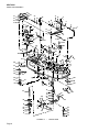
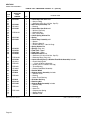
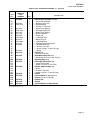
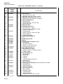
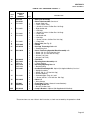
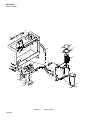
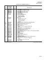
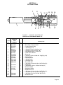
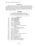
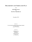
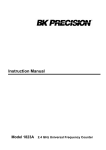
1
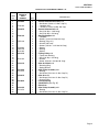
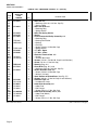
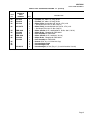
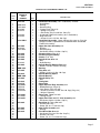
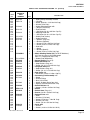
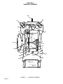
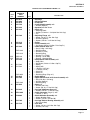
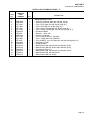
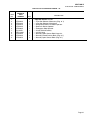
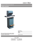
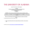
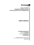
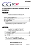
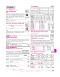
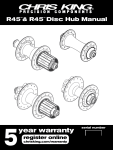
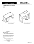
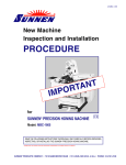
REPAIR PARTS CATALOG FOR
SUNNEN CYLINDER KING
AUTOMATIC VERTICAL HONING MACHINE
MODEL:
CV-616
THIS CATALOG COVERS THE
ABOVE MODEL FROM SERIAL
NO. 4333 TO 4721.
“SUNNEN, AND THE SUNNEN LOGO ARE TRADEMARKS OR REGISTERED TRADEMARKS OF SUNNEN® PRODUCTS COMPANY.”
SUNNEN PRODUCTS COMPANY
7910 MANCHESTER AVENUE • ST. LOUIS, MO 63143, U.S.A. • PHONE: 314-781-2100
X-CV-2900D
Like any machinery, this equipment may
be dangerous if used improperly. Be
sure to read and follow instructions for
operation of equipment.
ii
INTRODUCTION
Illustrations show all major components in exploded detail. Item numbers on each illustration are keyed to
the corresponding parts list, providing a descriptive identification of each part.
The parts lists include assemblies as well as detail parts. An item listed without a part number can be
obtained as a component of the complete assembly of which it is a part.
Standard hardware items are listed with complete descriptions, such as Item 29 below. These may be
purchased at your local hardware store, but it is important to replace an item with one having the same
dimensions as the original. In some places brand names and part numbers are shown. These may change
depending upon availability.
Sunnen Products Company reserves the right to make changes, without notice, to materials,
specifications, colors, designs and accessories included with units.
HOW TO ORDER
When ordering replacement parts be sure to include the following information to ensure prompt shipment of
correct parts:
1. The part number and description of each part desired, obtained from this parts catalog.
2. The quantity of each part desired.
3. The voltage, frequency and phase, when ordering electrical parts.
4. The model and serial number of the machine, obtained from the name plate, where there is any question
concerning a part.
HOW TO USE THIS PARTS LIST
Step 1. – Locate desired part on illustration. Note item number.
Step 2. – Locate item number in the parts list.
Step 3. – If the item has a part number listed, order by part number and the description. A part number in
light face type indicates that it is a component of the last preceding part number in bold face
type.
Step 4. – If no number is listed, order the part number of the unit of which the desired part is a component.
ORDER ONLY BY PART NUMBER AND DESCRIPTION – NOT by item number.
NOTE: In this manual, parts may be followed by “(For CE Machines)” or “(For Non-CE Machines)” to denote
domestic machines from exported machines. The CE version is constructed to meet the requirements of the
European market, and is available to any customer.
1
Step 1.
4
2
3
15
17
14
Step 2.
Step 3.
Step 4.
ITEM
NO.
ORDER BY
PART
NUMBER
QTY.
1
2
3
4
MVH-4499A
PHSM-405
PHW-354
MVH-4422
1
3
3
1
....Spindle Cap includes
......Screw (M6 x 1 x 16 SHCS)
......Washer (M6)
....Inner Spindle Nose
14
15
16
17
PEM-870A
PEM-871
PEM-872
PHSM-600
1
1
1
1
....Cable Carrier includes
......Cable Carrier Bracket
......Cable Carrier Bracket
....Screw (M3 x 0,5 x 5mm FHCS)
iii
DESCRIPTION
GENERAL INFORMATION
The Sunnen® equipment has been designed and engineered for a wide variety of parts within the capacity and limitation of the equipment. With proper care
and maintenance this equipment will give years of service.
READ THE FOLLOWING INSTRUCTIONS CAREFULLY AND THOROUGHLY BEFORE UNPACKING, INSPECTING, OR INSTALLING THIS
EQUIPMENT.
IMPORTANT: Read any supplemental instructions BEFORE installing this equipment. These supplemental instructions give you important information to
assist you with the planning and installation of your Sunnen equipment.
Sunnen Technical Service Department is available to provide telephone assistance for installation, programming, & troubleshooting of your Sunnen
equipment. All support is available during normal business hours, 8:00 AM to 4:30 PM Central Time. Emergency breakdown support is available on a 24
hour / 7 day basis.
Review all literature provided with your Sunnen equipment. This literature provides valuable information for proper installation, operation, and maintenance
of your equipment. Troubleshooting information can also be found within the Instructions. If you cannot find what you need, call for technical support.
Where applicable, programming information for your Sunnen equipment is also included. Most answers can be found in the literature packaged with your
equipment.
Help us help you. When ordering parts, requesting information, or technical assistance about your equipment, please have the following
information available:
• Have ALL MANUALS on hand. The Customer Services Representative or Technician will refer to it.
• Have Model Number and Serial Number printed on your equipment Specification Nameplate.
• Where Applicable: Have Drive model and all nameplate data. Motor type, brand, and all nameplate data.
For Troubleshooting, additional information may be required:
• Power distribution information (type - delta, wye, power factor correction; other major switching devices used, voltage fluctuations)
• Installation Wiring (separation of power & control wire; wire type/class used, distance between drive and motor, grounding).
• Use of any optional devices/equipment between the Drive & motor (output chokes, etc.).
For fast service on your orders call:
Sunnen Automotive Customer Service toll free at: 1-800-772-2878
Sunnen Industrial Customer Service toll free at: 1-800-325-3670
Customers outside the USA, contact your local authorized Sunnen Distributor.
Additional information available at: http://www.sunnen.com or e-mail: [email protected]
NOTE: Sunnen reserves the right to change or revise specifications and product design in connection with any feature of our products contained herein.
Such changes do not entitle the buyer to corresponding changes, improvements, additions, or replacements for equipment, supplies or accessories
previously sold. Information contained herein is considered to be accurate based on available information at the time of printing. Should any discrepancy of
information arise, Sunnen recommends that user verify the discrepancy with Sunnen before proceeding.
ESD PREVENTION REVIEW
Let's review the basics of a sound static control system and its effective implementation. First, in the three step plan:
1.
Always ground yourself when handling sensitive components or assemblies.
2.
Always use a conductive or shielded container during storage or transportation. These materials create a Faraday
cage which will isolate the contents from static charges.
3.
Open ESD safe containers only at a static safe work station.
At the static safe work station, follow these procedures before beginning any work:
A.
Put on your wrist strap or foot grounding devices.
B.
Check all grounding cords to make sure they are properly connected to ground, ensuring the effective dissipation of static charges.
C.
Make sure that your work surface is clean and clear of unnecessary materials, particularly common plastics.
D.
Anti-static bubble wrap has been included for use at the machine when an ESD safe workstation is not available.
You are now properly grounded and ready to begin work. Following these few simple rules and using a little common sense will go a long
way toward helping you and your company in the battle against the hazards of static electricity. When you are working with ESD sensitive devices, make sure you:
GROUND
ISOLATE
NEUTRALIZE
iv
SUNNEN® LIMITED PRODUCT WARRANTY
Sunnen® Products Company and its subsidiaries (SPC) warrant that all new SPC honing machines, gaging equipment, tooling, and related equipment will
be free of defects in material and/or workmanship for a period of one year from the date of original shipment from SPC.
Upon prompt notification of a defect during the one-year period, SPC will repair, replace, or refund the purchase price, with respect to parts that prove to be
defective (as defined above). Any equipment or tooling which is found to be defective from improper use will be returned at the customer's cost or repaired
(if possible) at customer's request. Customer shall be charged current rates for all such repair.
Prior to returning any SPC product, an authorization (RMA#) and shipping instructions must be obtained from the Customer Service Department or items
sent to SPC will be returned to the customer.
Warranty Limitations and Exclusions This Warranty does not apply to the following:
• Normal maintenance items subject to wear and tear: (belts, fuses, filters, etc).
• Damages resulting from but not limited to:
› Shipment to the customer (for items delivered to customer or customer's agent F.O.B., Shipping Point)
› Incorrect installation including improper lifting, dropping and/or placement
› Incorrect electric power (beyond +/- 10% of rated voltage) including intermittent or random voltage spikes or drops
› Incorrect air supply volume and/or pressure and/or contaminated air supply
› Electromagnetic or radio frequency interference from surrounding equipment (EMI, RFI)
› Storm, lightning, flood or fire damage
› Failure to perform regular maintenance as outlined in SPC manuals
› Improper machine setup or operation causing a crash to occur
› Misapplication of the equipment
› Use of non-SPC machines, tooling, abrasive, fixturing, coolant, repair parts, or filtration
› Incorrect software installation and/or misuse
› Non-authorized customer installed electronics and/or software
› Customer modifications to SPC software
THE LIMITED WARRANTY DESCRIBED HEREIN IS EXPRESSLY IN LIEU OF ALL ANY OTHER WARRANTIES. SPC MAKES NO REPRESENTATION OR WARRANTY OF
ANY OTHER KIND, EXPRESS OR IMPLIED, WHETHER AS TO MERCHANTABILITY, FITNESS FOR A PARTICULAR PURPOSE OR ANY OTHER MATTER. SPC IS NOT
RESPONSIBLE FOR THE IMPROPER USE OF ANY OF ITS PRODUCTS. SPC SHALL NOT BE LIABLE FOR DIRECT, INDIRECT, INCIDENTAL, OR CONSEQUENTIAL
DAMAGES INCLUDING BUT NOT LIMITED TO: LOSS OF USE, REVENUE, OR PROFIT. SPC ASSUMES NO LIABILITY FOR PURCHASED ITEMS PRODUCED BY OTHER
MANUFACTURERS WHO EXTEND SEPARATE WARRANTIES. REGARDLESS OF ANY RIGHTS AFFORDED BY LAW TO BUYER, SPC's LIABILITY, IF ANY, FOR ANY AND
ALL CLAIMS FOR LOSS OR DAMAGES WITH RESPECT TO THE PRODUCTS, AND BUYER'S SOLE AND EXCLUSIVE REMEDY THEREFORE, SHALL IN ALL EVENTS BE
LIMITED IN AMOUNT TO THE PURCHASE PRICE OF THAT PORTION OF THE PRODUCTS WITH RESPECT TO WHICH A VALID CLAIM IS MADE.
Shipping Damages
Except in the case of F.O.B., Buyer's destination shipments, SPC will not be liable for any settlement claims for obvious and/or concealed shipping damages.
The customer bears the responsibility to unpack all shipments immediately and inspect for damage. When obvious and/or concealed damage is found, the
customer must immediately notify the carrier's agent to make an inspection and file a claim. The customer should retain the shipping container and packing
material.
SUNNEN® SOFTWARE LICENSE AGREEMENT
This document is a Legal Agreement between you, as user and licensee (Licensee), and Sunnen® Products Company (SPC) with respect to preprogrammed
software (Software) provided by SPC for use on SPC Equipment. By using the Software, you, as Licensee, agree to become bound by the terms of this
Agreement.
In consideration of payment of the license fee (License Fee) which is part of the price evidenced by your receipt (Receipt), SPC grants to you as Licensee
a non-exclusive right, without right to sub-license, to use the particular copy of the SPC Software licensed hereunder only on the particular equipment sold with
the Software. SPC reserves all rights including rights not otherwise expressly granted, and retain title and ownership to the Software including all subsequent copies or updates in any media. The Software and all accompanying written materials are covered by copyrights owned by SPC. If supplied on
removable media (floppy disk), you, as Licensee, may copy the Software only for back up purposes; or you may request that SPC copy the Software for you
for the same purposes. All other copying of the Software or of the accompanying written materials is expressly forbidden and is in violation of the Agreement.
The Software and accompanying written materials (including the user's manual, if any) are provided in an "as is" condition without warranty of any kind
including the implied warranties of merchantability and fitness for a particular purpose, even if SPC has been advised of this purpose. SPC specifically does
not warrant that it will be liable as a result of the operation of the Software for any direct, indirect, consequential or accidental damages arising out of the
use of or inability to use such product even if SPC has been advised of the possibility of such use. It is recognized that some states do not allow the exclusion or limitation of liability for consequential or accidental damages and to the extent this is true, the above limitations may not apply.
Any alteration or reverse engineering of the software is expressly forbidden and is in violation of this agreement.
SPC reserves the right to update the software covered by this agreement at any time without prior notice and any such updates are covered by this
agreement.
v
SAFETY INSTRUCTIONS
READ FIRST
This machine, like any equipment, may be dangerous if used improperly. Please
read all warnings and instructions before attempting to use this machine.
Always disconnect power at main enclosure before servicing machine.1
Always wear eye protection when operating this machine.
NEVER open or remove any machine cover or protective guard with power "ON."
Always disconnect power at main enclosure before servicing this equipment.1
DO NOT attempt any repair or maintenance procedure beyond those described in
this book. Contact your Sunnen® Field Service Engineer or Technical Services
Representative for repairs not covered in these instructions.
Due to the wide variety of machine configurations, all possibilities cannot be
described in these instructions. Instructions for safe use and maintenance of
optional equipment ordered through Sunnen, will be provided through separate
documentation and/or training provided by your Sunnen Field Service Engineer or
Technical Services Representative.
DO NOT attempt to defeat any safety device on this machine or on any of the
optional equipment.
If specially built automation components are added to this system, be sure that
safety is not compromised. If necessary, obtain special enlarged work area safety
system from Sunnen Products Co.
Indicates CE version ONLY.
1
DO NOT touch electrical components until main input power has been turned off and CHARGE
lamps are extinguished. WARNING: The capacitors are still charged and can be quite dangerous.
vi
CONTENTS
PAGE
Introduction ..........................................................................................................
How To Order ......................................................................................................
How To Use This Parts List .................................................................................
General Information .............................................................................................
ESD Prevention Review ......................................................................................
Limited Product Warranty ....................................................................................
Sunnen Software License Agreement ..................................................................
General Safety Instructions ..................................................................................
Contents ...............................................................................................................
iii
iii
iii
iv
iv
v
v
vi
1
SECTION I DRIVE ARM ASSEMBLY
A Drive Arm.............................................................................................................. 2
B Drive Arm ............................................................................................................. 6
C Drive Arm ............................................................................................................. 10
D Gear Reducer & Related Parts............................................................................. 12
SECTION II CARRIAGE ASSEMBLY
E Carriage Assembly ............................................................................................... 16
SECTION III ELECTRICAL COMPONENTS
F Electrical Panel ..................................................................................................... 18
G Operator Station ................................................................................................... 20
SECTION IV BASE ASSEMBLY
H Right Front View ................................................................................................... 22
I Left Front View ..................................................................................................... 24
J Rear View ............................................................................................................. 26
SECTION V OPTIONAL ITEMS
K Mandrel Adapter Unit............................................................................................ 29
L Clamp Kit .............................................................................................................. 30
“KGM, KROSSGRINDING, SUNNEN, AND THE SUNNEN LOGO ARE TRADEMARKS OR REGISTERED TRADEMARKS OF SUNNEN® PRODUCTS COMPANY.”
© Copyright 2002 by Sunnen® Products Company • Printed in U.S.A.
Page 1
SECTION I
DRIVE ARM ASSEMBLY
4
3
42
44
45
6
41
1
22
39
2
38
5
46
47
48
37
62
63
22
32
21
24
8
9
25
26
10
40
28
12
27
65
43
11
34 25
33
64
7
28A
68
67
35
26A
23
23
30
29
31
36
49
66
56
57
60
52
13
14
51
10
53A
53
59
15
50
16
18
17
19
20
55
54
FIGURE A – DRIVE ARM
Page 2
58
61
SECTION I
DRIVE ARM ASSEMBLY
PARTS LIST COVERING FIGURE “A”
ITEM
NO.
1
2
3
4
5
6
18
7
8
9
10
11
12
13
14
15
16
17
18
19
20
21
22
23
24
25
26
27
26
28
29
30
31
32
25
26
ORDER BY
PART
NUMBER
CV-206A
CV-610A
CV-207A
CV-613A
PBR-12A
CV-208A
PBR-13A
CK-218A
CK-211A
CK-219A
CV-331A
CV-195A
CV-197A
CV-201A
CK-203A
CV-325A
CV-197A
N/S indicates Not Shown
QTY.
1
1
1
2
1
1
1
1
1
4
2
4
4
1
1
1
1
1
1
1
1
1
1
1
1
1
1
1
1
1
1
1
1
1
1
1
DESCRIPTION
....Second Countershaft Pulley with
......Set Screw (1/4-20 x 1/2 Soc. Cup Pt.)
......Lockplate with
........Screws (1/4-20 x 5/8 But. Hd. Cap)
....Second Countershaft with
......Key (3/16 Sq. x 1-3/8 Long)
......Key (3/16 Sq. x 3/4 Long)
....Bearing Support with
......Lockplate
......Screws (10-24 x 3/4 Hex Hd. Cap)
......Bearing (Pkg. of 1)
......Washer (3/8 Lock)
......Screws (3/8-16 x 1-1/2 Hex Hd. Cap)
......Spacer
......Bearing
......Spacer
....Timing Pulley with
......Taper Lock Bushing
......Key (3/16 Sq. x 3/4 Long)
......Washer
......Screw (5/16-24 x 3/4 Hex Hd. Cap)
....Idler Arm Shaft with
......Retaining Ring
......Spring Washer
....Idler Pulley Assembly with
......Bearing
......Set Screw (5/16-18 x 1/2 Soc. Cup Pt.)
....Idler Arm with
......Set Screw (5/16-18 x 1/2 Soc. Cup Pt.)
......Grease Fitting
....Tension Spring
....Hand Wheel (See Fig. “B”)
....Drive Arm
....Idler Pulley Assembly with
......Bearing
......Set Screw (5/16-18 x 1/2 Soc. Cup Pt.)
(Parts continued on next page)
Page 3
SECTION I
DRIVE ARM ASSEMBLY
PARTS LIST COVERING FIGURE “A” (cont’d)
ITEM
NO.
33
26
28
34
22
23
35
36
37
38
39
40
41
42
43
44
45
46
N/S
N/S
47
48
49
50
51
52
53
53A
54
55
56
57
58
59
60
61
58A
59A
60
61
ORDER BY
PART
NUMBER
CV-332A
CV-202A
CV-334A
CK-333A
CV-190A
PBR-36A
MBB-335C
PHW-122A
CK-209A
CK-498A
CK-553A
CK-552GA
PBR-10A
CV-773A
CV-818A
CK-156A
CK-1444A
CV-605A
CV-608A
CV-606A
CV-605MA
CV-608MA
CV-606A
N/S indicates Not Shown
Page 4
QTY.
1
1
1
1
1
1
1
1
1
1
1
1
1
1
1
1
1
1
1
1
3
1
2
2
2
1
1
1
1
4
1
1
1
1
1
2
1
1
1
2
DESCRIPTION
....Idler Arm with
......Set Screw (5/16-18 x 1/2 Soc. Cup Pt.)
......Grease Fitting
....Idler Arm Shaft with
......Retaining Ring
......Spring Washer
....Idler Arm Spring Anchor
....Spring
....First Countershaft Pulley Assembly with
......Retaining Ring
......Bearing with Washer
......Bearing
......End Cap
......Screw (1/4-20 x 3/4 Hex Hd. Cap)
......Spring Washer
....“V” Belt - Upper
....“V” Belt - Lower
....Electrical Terminal Box with
......Gasket
......Terminal Box Cover
....Screws (1/4-20 x 7/8 Hex Hd. Cap & Lock Washers)
....Screw (1/4-20 x 1” Hex Hd. Cap)
....Bearing (Pkg. of 1)
....Pivot Shaft (Pkg. of 1) with
......Set Screw (5/16-18 x 3/4 Soc. Cup Pt.)
....Shock Absorber Plate with
......Screw (1/4-20 x 3/4 Hex Hd. Cap)
......Washer (1/4 Lock)
....Gear Reducer & Related Parts (See Fig. “D”)
....Screws (3/8-16 x 1” Hex Hd. Cap & Lock Washers)
....Indicator Light with
......Incandescent Lamp
....Index Plate Assemby with
......Index Plate
......Ball Plunger
......Screws (10-24 x 1” Soc. Hd. Cap)
....Index Plate Assembly (Metric) with
......Index Plate (Metric)
......Ball Plunger
......Screws (10-24 x 1” Soc. Hd. Cap)
(Parts continued on next page)
SECTION I
DRIVE ARM ASSEMBLY
PARTS LIST COVERING FIGURE “A” (cont’d)
ITEM
NO.
ORDER BY
PART
NUMBER
62
62
63
CK-192A
CV-267A
CK-152A
63
CK-152FA
64
66
PMO-822A
CV-240A
CV-241A
PMO-823A
CV-244A
CV-246A
64
66
65
67
68
CK-3451A
QTY.
1
1
1
1
1
1
1
1
1
1
1
1
4
1
1
6
DESCRIPTION
....Flat Belt (3/4” wide x 51” long) 60 Hz
....Flat Belt (3/4” wide x 53” long) 50 Hz
....Motor Pulley (for 230/460 volt, 60 Hz, 3 Ph.) with
......Set Screw (5/16-18 x 1/2 Soc. Cup Pt.)
....Motor Pulley (for 220/380/440 Volt, 50 Hz, 3 Ph.) with
......Set Screw (5/16-18 x 1/2 Soc. Cup Pt.)
....Motor & Brake (2 HP, 208/230/460 V, 60 Hz, 380 V, 50 Hz)
....Motor Brake - Complete for PMO-822A
....Coil Assembly for PMO-822A
....Motor & Brake (2 HP, 220/440 V, 50 Hz)
....Motor Brake - Complete for PMO-823A
....Coil Assembly for PMO-823A
....Screws (5/16-18 x 1-1/4 Hex Hd. Cap)
....Counterweight, Right
....Counterweight, Left
....Counterweight (1/8” thick) (Pkg. of 1) (Located in Handwheel - Item 30)
N/S indicates Not Shown
Page 5
SECTION I
DRIVE ARM ASSEMBLY
3
2
1
4
5
6
7
14
15
8
16
18
17
9
11
19
10
10A
21
12
12
20
13
12
12
38
40
37A
34
35
36
22
23
26
27
27A
28
28
29 30
24
39
41
33
37
31
25
32
FIGURE B – DRIVE ARM
Page 6
30
29
SECTION I
DRIVE ARM ASSEMBLY
PARTS LIST COVERING FIGURE “B”
ITEM
NO.
ORDER BY
PART
NUMBER
CV-215A
1
2
3
4
5
6
7
8
9
MBB-335C
PHR-303A
CK-226A
CK-227A
CV-220A
CK-229A
CV-215M-A
10
10A
3
11
12
13
N/S
14
15
16
17
18
19
20
21
22
23
24
15
25
26
27
27A
28
29
30
31
32
33
11
34
35
36
37
37A
38
39
40
41
CK-230A
CK-233A
PHR-303A
CK-234A
CK-235A
CK-238A
CK-240A
CK-242A
CK-246A
MBB-335C
CK-229A
CK-243A
MBB-340A
CK-248A
CK-252A
CV-251A
CV-1825A
PBR-23A
PBR-24A
PHS-522A
CV-1830A
CK-1823A
CV-1835A
CK-328A
CK-160A
CK-162A
CK-323A
QTY.
1
1
1
1
4
4
4
1
1
4
1
1
1
1
1
4
1
1
1
1
1
1
4
1
1
4
1
1
1
1
1
1
1
4
4
4
4
1
1
1
1
1
1
1
1
1
1
1
1
1
DESCRIPTION
....Hand Wheel Assembly (.001” Graduations) Includes
......Hand Wheel
......Bearing
......Retaining Ring
......Plungers with (Pkg. of 4)
........Springs (Pkg. of 4)
........Set Screws (3/8-24 x 3/8 Soc. Cone Pt.)
......Graduated Feed Dial Assembly (.001” Graduations)
......Ring Gear with
........Screws (10-24 x 1/2 Soc. Hd. Cap)
....Hand Wheel Assembly - Metric (All parts the same as CV-215A
except CV-220A is replaced with CV-220M-A Metric Graduated
Feed Dial Assembly)
....Upper Sun Gear Assembly with
......Bushing
......Retaining Ring
......Set Screw (3/8-24 x 3/8 Soc. Cup Pt.)
....Planetary Gears (Pkg. of 4)
....Planetary Cage Assembly
....Grease (1 Lb. Can)
....Spindle & Sun Gear with
......Key
......Nylon Bearing
....Spindle Bearing Retainer Ring with
......Screws (1/4-20 x 5/8 Soc. Hd. Cap)
....Bearing
....Ring Gear with
......Screws (10-24 x 1/2 Soc. Hd. Cap)
....Spindle Bearing Spacer
....Spindle Bearing
....Spindle Pulley with
......Key
....Timing Belt
....Drive Yoke
....Upper Universal Ring Assembly with
......Needle Bearings (Pkg. of 4)
......Inner Races (Pkg. of 4) with
........Screws (5/16-24 x 7/8 Soc. But. Hd. Cap) (Pkg. of 4)
........Washers (Special)
....Drive Tube - Upper Half with
......Locking Screw
....Upper Feed Tube and “U” Joint Assembly with
......Set Screw (3/8-24 x 3/8 Soc. Cup Pt.)
....Back Stop for Timing Belt with
......Washer (3/8 Plain)
......Screw (3/8-16 x 1” Hex Hd. Cap)
....Idler Pulley Assembly with
......Bearing
....Final Drive Idler Arm with
......Set Screw (5/16-18 x 5/16 Soc. Cup Pt.)
......Washer (1/2 Lock)
......Screw (1/2-13 x 1-1/4 Hex Hd. Cap)
N/S indicates Not Shown
Page 7
SECTION I
DRIVE ARM ASSEMBLY
28
14
29
33
32
30
27
11
54
28
25
53
31
8
7
26
9
13
23 24
46
43
10
6
24A
19
43A
44
51
42
8
22
21
20
39
18
15
38
41
35
37
12
52
40
109
45
50
108
109
35
36
30
110
111
49
55
3
112
60
2
107
106
1
56
5
4
57
59
58
60
56
47
102
64
62
81
82
83
84
73
63
61
90
98
66
105
74
85
86
79
78
87
75
104
77
76
79
67
99
88
92
96
89
97
71
91
93
94
95
FIGURE C – DRIVE ARM
Page 8
103
72
65
68
69
70
101
100
SECTION I
DRIVE ARM ASSEMBLY
PARTS LIST COVERING FIGURE “C”
ITEM
NO.
1
2
3
4
5
6
7
8
9
10
11
12
13
14
15
18
19
20
21
22
23
24
24A
25
26
27
28
29
14
30
31
32
33
34
35
36
37
38
39
ORDER BY
PART
NUMBER
CK-345A
CK-348A
CK-352A
CK-353A
CK-355A
CK-358A
PHR-305A
CK-365A
EL-11A
CK-374A
CK-335A
CK-339A
CK-368A
CK-341A
CK-364A
CK-371A
CK-373A
CK-374A
CK-175A
CK-183A
CK-182A
CK-165A
PHR-302A
N/S indicates Not Shown
QTY.
1
1
1
1
1
1
1
2
1
1
1
1
1
1
1
1
1
1
1
1
1
1
1
1
1
1
1
3
1
1
1
1
1
1
1
2
1
1
1
1
DESCRIPTION
....Clutch Control Lever Assembly with
......Knob
....Clutch Handle Pivot Screw
....Stop Sleeve with
......Screw (10-24 x 3/4 Soc. Hd. Cap)
....Clutch Pull Rod Assembly (Front) with
......Adjusting Link
......Retaining Ring (Pkg. of 1)
......Nut (5/16-18 Hex Jam)
......Nut (5/16-18 Hex)
......Screw (5/16-18 x 3/4 Hex Hd. Cap)
....Clutch Pull Rod Assembly (Rear) with
......Spring
......Spring
....Feed Finger Release Bar Assembly Includes
......Release Bar
......Nylon Sleeve
....Sleeve
....Sleeve with
......Washer (3/8 Plain)
......Screw (3/8-16 x 1” Hex Hd. Cap)
....Clevis with
......Screw (5/16-18 x 1” Hex Hd. Cap)
......Washer (5/16 Lock)
....Set Collar with
......Set Screw (10-32 x 1/4 Soc. Cup Pt.)
....Clutch Adjusting Nut with
......Nuts (5/16-18 Hex)
......Spacer
......Spring
....Clutch Actuating Arm Assembly with
......Shouldered Pivot Spacer
......Washer (5/16 Plain)
......Screw (5/16-18 x 1-1/2 Hex Hd. Cap)
......Clevis Pin
......Spacers
......Hair Pin Cotter
....Connecting Link Assembly with
......Washer (5/16 Plain)
......Retaining Ring
(Parts continued on next page)
Page 9
SECTION I
DRIVE ARM ASSEMBLY
PARTS LIST COVERING FIGURE “C” (cont’d)
ITEM
NO.
40
41
42
43
43A
44
45
46
47
49
50
51
52
53
54
55
56
57
58
59
60
61
62
63
64
65
66
67
68
69
70
71
72
73
74
75
76
77
ORDER BY
PART
NUMBER
CK-163A
CK-160A
CK-162A
CK-164A
PHR-301A
CK-172A
CK-185A
CK-267A
CK-255A
CK-265A
CK-269A
PHR-304A
CK-270A
CK-271A
PBR-27A
PBR-25A
CK-280A
CK-89A
CK-90A
PBR-30A
CK-92A
CK-312A
CK-120A
PBR-31A
PSP-101A
N/S indicates Not Shown
Page 10
QTY.
1
1
1
1
1
1
1
1
1
1
1
1
1
1
1
1
2
1
1
1
1
2
1
1
1
4
1
1
1
1
1
1
1
1
1
1
1
1
1
1
1
1
DESCRIPTION
....Clutch Idler Arm & Pin with
......Grease Fitting
......Set Screw (5/16-18 x 1/2 Soc. Cup Pt.)
....Idler Pulley Assembly with
......Bearing
....Clutch Idler Arm Shaft with
......Washer (5/8 Plain)
......Retaining Ring
......Nut (1/2-13 Hex)
....Clutch Spring Anchor Pin
....Spring
....Clutch Stop Assembly with
......Spacer
......Washer (Special)
......Screw (3/8-16 x 1” Hex Hd. Cap)
....Spring Anchor Pin
....Springs (Pkg. of 2)
....Feed Pawl - Upper
....Feed Pawl - Lower
....Double Eccentric with
......Set Screw (1/4-28 x 5/16 Soc. Cup Pt.)
......Retaining Rings (Pkg. of 2)
....Clutch Housing Ass’y & Ratchet Feed Shaft Assembly Includes
......Clutch Housing with
..........Clutch & Bearing Assembly
......Screws (10-24 x 1/2 Soc. Hd. Cap)
......Thrust Bearing
......Ratchet Feed Shaft Assembly
....Ratchet Wheel
....Selector Cover Assembly Includes
......Selector Cover
......Bearing
......Nylon Thrust Bearing
....Shoulder Bushing
....Retaining Nut
....Selector Body Assembly Includes
......Selector Body
......Bearing
......Groov-Pin
......Compression Spring
......Spring Washer
......Selector Lever
(Parts continued on next page)
SECTION I
DRIVE ARM ASSEMBLY
PARTS LIST COVERING FIGURE “C” (cont’d)
ITEM
NO.
ORDER BY
PART
NUMBER
CK-290A
78
79
81
82
83
84
85
86
87
88
89
90
91
92
93
94
95
96
97
98
99
100
101
102
103
104
105
106
107
108
N/S
109
110
111
N/S
CK-293A
PHR-311A
CK-123A
PHW-122A
CK-118A
CK-117A
CK-296A
PHR-305A
CK-297A
PHR-306A
CK-125A
CK-308A
CK-309A
CK-317A
CK-318A
CK-293A
CK-157A
CK-530A
CK-362A
CK-214A
CK-431A
CK-213A
CK-214A
QTY.
1
1
2
1
1
1
1
1
1
1
1
1
1
1
1
1
1
1
1
2
1
1
1
1
1
2
1
2
2
2
1
1
4
1
1
1
DESCRIPTION
....Ratchet Arm Assembly Includes
......Arm & Hub Assembly
......Bushings (Pkg. of 2)
......Retaining Ring
......Washer (1-1/64 Plain)
......Nylon Thrust Washer
......Wave Spring Washer
......Nylon Thrust Washer
......Washer (Special)
......Clevis with
........Retaining Ring
......Swivel Pin with
........Retaining Ring
......Ratchet Pawl Assembly with
........Shoulder Bushing
........Washer (1/4 Plain)
........Screw (1/4-28 x 1” Soc. Hd. Cap)
........Spring
....Spring with
......Nuts (5/16-24 Hex)
....Shouldered Set Collar with
......Set Screw (10-32 x 1/4 Soc. Cup Pt.)
....Bushing (Pkg. of 2)
....Pilot Light Cover Plate with
......Cover Plate Gasket
......Screws (10-24 x 1/2 Truss Hd.)
....Rocker Stop Assembly with
......Shims
......Washers (3/8 Lock)
......Screws (3/8-16 x 1” Hex Hd. Cap)
....Switch
....Contact Block for Above Switch
....Screws (10-32 x 2” Rd. Hd.)
....Switch Arm
....Switch
....Contact Block For Above Switch
N/S indicates Not Shown
Page 11
SECTION I
DRIVE ARM ASSEMBLY
79
78
81
34
76
75
80
33
30
28
76
76
29
(6LS)
75
31
32
11
143
74
142
24
140
12
4
2
1A
1
21
25
20
25
141
72
19
93
27
26
28
92
17
70
62
13
144
45
142
49
143
46
71
45
66
47 48
135
10
6
9
5
3
67
68
64
63
8
(1 SOL)
28
73
44
46
3A
50
7
14
18
43
15
86
91
51
136
90
147
36
87
91
115
116
114
35
(3LS)
73
65
69
16
42
88
89
114
113
113
111 & 111A
102
101
115
123
96
94
97
137
116
122
95
112
119
118
100
117
121
103
123
138
(4LS)
138
(1LS)
124
105
95
139
124
104
106
98
99
95
127
108
107
125
131
126
129
130
FIGURE D – GEAR REDUCER & RELATED PARTS
Page 12
128
109
110A
110
SECTION I
DRIVE ARM ASSEMBLY
PARTS LIST COVERING FIGURE “D”
ITEM
NO.
ORDER BY
PART
NUMBER
1
1A
CV-625A
2
3
3A
4
5
6
7
8
9
10
11
12
13
CK-401C
14
15
16
17
18
CV-446A
N/S
N/S
N/S
N/S
N/S
N/S
N/S
N/S
N/S
19
20
21
24
25
26
27
28
29
N/S
30
N/S
31
32
33
34
35
36
CK-439A
CK-443A
CK-442A
CK-444A
CK-438A
CK-454A
CK-448A
CV-451A
CV-452A
CK-408A
CK-402A
CK-403A
PHR-307A
CK-404C
CK-407A
CV-390A
PHR-305A
CK-410A
CK-414A
CK-416A
CK-417A
PHR-308A
CK-421A
CK-214A
CK-422A
CK-422-2A
CK-423A
PES-151A
PES-200A
N/S indicates Not Shown
QTY.
1
2
2
1
1
1
1
1
1
1
1
4
4
1
1
2
2
1
1
1
1
4
4
1
1
2
2
1
1
1
1
1
1
1
1
2
1
1
1
1
1
1
1
1
1
1
2
1
1
DESCRIPTION
....Side Plate with
......Screws (1/4-20 x 5/8 Hex Hd. Cap)
......Washers (1/4 Lock)
....Threaded Sleeve with
......Nut (7/8-14 Hex Jam)
......Lockwasher (7/8 Shakeproof)
....Solenoid Plunger with
......Spring
......Washer (1/2 Plain)
......Retaining Ring
....Solenoid with
......Screws (1/4-20 x 1/2 Soc. Hd. Cap)
......Washers (1/4 Lock)
....Clevis Pin with Cotter
....Angle Bracket with Washer
....Screws (1/4-20 x 5/8 Hex Hd. Cap)
....Washers (1/4 Lock)
....Gear Reducer with
......Oil Drain Plug
......Oil Level Plug
......Oil Filler & Vent Plug
......Screws (3/8-16 x 1” Hex Hd. Cap)
......Washers (3/8 Lock)
....Bearing Set For CV-446A Gear Reducer - (7/8” Shaft)
....Replacement Shaft Kit For CV-446A Gear Reducer - (7/8” Shaft) with
......Gaskets (Pkg. of 2)
......Grease Seals (Pkg. of 1)
....Bearing Set For CV-446A Gear Reducer - (5/8” Shaft)
....Grease Seal For 5/8” Shaft
....Gear Oil For CV-446A Gear Reducer (One Quart)
....Slow Speed Worm Gear (Bronze)
....High Speed Worm & Shaft Integral
....Shoulder Stud with
......Nut (1/4-20 Hex)
......Retaining Ring
....Arm Assembly with
......Bearings (Pkg. of 2)
......Roller
......Pin
......Retaining Ring
....Switch
....Contact Block For Above Switch
....One Way Roller (Includes Washer & Nut) with
......Spring
......Switch Arm with
........Locking Screw
........Nut (10-32 Hex)
....Screws (10-32 x 1-3/4 Soc. Hd. Cap)
....Switch
....Switch Arm
(Parts continued on next page)
Page 13
SECTION I
DRIVE ARM ASSEMBLY
PARTS LIST COVERING FIGURE “D” (cont’d)
ITEM
NO.
42
43
44
45
46
47
48
49
50
51
62
63
64
65
66
67
68
69
70
71
72
73
74
75
76
28
78
79
80
81
86
87
88
89
90
91
92
93
ORDER BY
PART
NUMBER
CV-447A
CK-455A
CK-319A
CV-316A
CK-458C
CK-459A
CK-465C
CK-470A
CK-477A
CV-490A
CV-491A
CK-492A
PHR-308A
CV-494A
CK-498A
CV-538A
CV-638A
PBR-40A
PBR-16A
CK-541A
CV-505A
94
95
96
97
98
99
100
101
102
PBR-10A
CK-503A
CV-508A
PHR-327A
CV-507A
N/S indicates Not Shown
Page 14
QTY.
1
1
1
2
2
1
1
1
1
1
1
1
1
1
1
1
1
1
1
1
1
1
1
1
2
3
2
1
1
1
1
1
1
1
1
1
2
1
1
1
1
4
1
1
2
1
1
1
2
DESCRIPTION
....Feed Crank with
......Key (3/16 Sq. x 3/4 Long)
......Set Screw (5/16-18 x 1/2 Soc. Cup Pt.)
....Adjustable Cam Rings (Pkg. of 1) with
......Set Screw (1/4-20 x 3/8 Soc. Full Dog Pt.)
....Spherical Rod End with
......Spacer Washer
......Screw (5/16-24 x 1” Hex Hd. Cap)
......Nut (5/16-24 Hex)
....Feed Push Rod
....Stroking Crank Kit with
......Key (3/16 Sq. x 1” Long)
......Screw (7/16-20 x 1-3/4 Soc. Hd. Cap)
......Locknut (7/16-20 Hex)
......Flange Bushing
......Screw (1/2-20 x 2-1/2 Soc. Hd. Cap)
......Washer (Special)
......Locknut (1/2-20 Hex)
....Stroke Release Block with
......Pin
....Stroke Release Pawl
....Spring
....Actuating Link Assembly Includes
......Actuating Link
......Bushings (Pkg. of 2)
......Washers (1/4 Flat with C’sink)
......Retaining Rings (Pkg. of 1)
....Gear Reducer Pulley with
......Key (3/16 Sq. x 1” Long)
......Set Screw (15/16-18 x 3/8 Soc. Cup Pt.)
....“V” Belt - Lower
....Connecting Rod with
......Grease Fitting
......Screw with
........Bearing
........Bearing
........Washers (Special) (Pkg. of 2)
......Adjusting Nut
......Nut (1/2-20 Hex)
....Stroking Rocker Assembly (For 60 Hz Machines) Includes
......Stroking Rocker
......Bearings (Pkg. of 1)
......Set Screw (Special)
......Nut (1/2-13 Hex Jam)
......Grease Fittings
......Stroking Arm with
........Retaining Ring
......Retaining Plate with
........Screws (1/4-20 x 1” Soc. Hd. Cap)
(Parts continued on next page)
SECTION I
DRIVE ARM ASSEMBLY
PARTS LIST COVERING FIGURE “D” (cont’d)
ITEM
NO.
103
N/S
104
105
106
107
108
109
110
110A
111
112
113
114
115
116
117
118
119
116
ORDER BY
PART
NUMBER
CK-515A
PBR-17A
CV-509A
CK-517A
CV-521A
CV-1275A
CV-522A
CK-513A
CK-511A
CV-505M-A
111A
121
122
123
124
125
123
124
126
127
128
129
130
131
N/S
N/S
135
136
137
138
139
140
141
142
143
144
145
146
147
148
CV-1275M-A
CK-523A
CV-651A
CV-653A
CV-652A
CV-653A
CV-527A
CV-785A
CK-742A
CK-796A
CV-646A
PES-117A
CK-431A
CV-628A
CV-634A
CV-637A
CV-636A
QTY.
1
1
1
1
1
1
1
1
1
1
1
1
2
2
4
1
1
1
1
1
1
1
*
1
2
1
1
2
1
1
1
1
1
2
2
1
2
1
2
1
2
2
1
1
3
3
1
1
1
1
6
DESCRIPTION
......Sliding Clamp Assembly Includes
........Bearing
......Screw (5/16-24 x 1-1/4 Hex Hd. Cap)
......Washer (5/16 Plain)
......Stroke Adjusting Screw with
........Washer (9/32 Plain)
......End Plate with
........Set Screw (10-32 x 3/8 Soc. Cup Pt.)
......Adjusting Knob with
........Set Screw (10-32 x 1/4 Soc. Cup Pt.)
......Stroke Plate (Inches)
......Angle Plate with
........Spacers (Pkg. of 2)
........Washers (Special)
........Screws (10-32 x 3/8 But. Hd. Cap)
........Screw (10-32 x 1/4 But. Hd. Cap)
......Knob with
........Spring
........Washer (Special)
........Screw (10-32 x 1/4 But. Hd. Cap)
....Metric Stroking Rocker Kit (For 50 HZ Machines)
(All Parts the same as CV-505A except
Item 111 is replaced by item 111A)
......Stroke Plate (Millimeters)
....Spacer Washer (Pkg. of 3)
....Short Stub Shaft with
......Step Washers (Pkg. of 1)
......Screw (1/2-13 x 1-1/2 Hex Hd. Cap)
....Long Stub Shaft with
......Step Washers (Pkg. of 1)
......Screw (1/2-13 x 1-1/2 Hex Hd. Cap)
....Stop Collar with
......Set Screw (1/4-20 x 1/4 Soc. Cup Pt.)
....Connecting Link Assembly with
......Screw
......Grease Fittings
......Nuts (1/2-20 Hex)
......Screw (At lower end of Item 128)
......Spacers (At lower end of item 128)
....Switch Bracket with
......Screws (1/4-20 x 3/4 Soc. Hd. Cap)
....Switch
....Switch Arms (Pkg. of 1)
....Screws (10-32 x 3/4 Soc. Hd. Cap)
....Solenoid Case with
......Hook
......Washers (5/16 Lock)
......Screws (5/16-18 x 1” Hex Hd. Cap)
......Washer (1/4 Lock)
......Screw (1/4-20 x 3/4 Hex Hd. Cap)
....Cover with
......Gasket
......Screws (10-32 x 1/2 Rd. Hd. I.M.S.)
N/S indicates Not Shown
Page 15
SECTION II
CARRIAGE ASSEMBLY
20
19
19
18
14
21
13
12
7
8
15
1
6
5
22
11
10
4
9
2
3
FIGURE E – CARRIAGE ASSEMBLY
Page 16
SECTION II
CARRIAGE ASSEMBLY
PARTS LIST COVERING FIGURE “E”
ITEM
NO.
ORDER BY
PART
NUMBER
1
2
3
4
CK-707A
CK-780A
CK-781A
CK-775A
5
6
CK-734A
CK-723A
7
CK-718A
8
9
CK-721A
CV-730A
10
CK-728A
PHR-312A
PHR-311A
N/S
N/S
11
PBR-19A
PBR-10A
CV-745A
12
13
CK-758A
CV-759A
14
15
PHR-305A
CK-362A
CK-710A
17
PHR-310A
CK-764A
18
CV-763A
19
PEC-106A
20
CV-660A
21
CV-770A
22
CK-772A
N/S indicates Not Shown
QTY.
2
1
1
1
1
1
1
1
2
1
1
1
2
2
1
1
1
1
1
1
1
1
1
1
1
1
1
1
1
1
1
1
1
1
2
1
1
1
1
1
1
1
1
1
2
2
2
1
1
4
1
1
1
1
1
DESCRIPTION
....Bushings
....Oil Spout Sleeve
....Clamp Nut
....Clamp Knob Assembly with
......Washer (Special)
....Sprocket with Set Screw
....Chain with
......Adjusting Block
......Screws (5/16-24 x 1-1/4 Nylok Soc. Hd. Cap)
......Pin
....Adjusting Flange with
......Screw (1/4-20 x 1” Soc. Hd. Cap)
......Washers (Special)
......Screws (3/8-16 x 1-1/4 Hex Hd. Cap)
....Pulley
....Lever Assembly with
......Set Screw (3/8-16 x 5/8 Soc. Plain Cup Pt.)
....Lower Control Shaft with
......Key (1/4 Sq. x 3/4 Long)
......Retaining Ring
......Washer (1” Plain)
......Retaining Ring
......Washer (1-1/4 Plain)
......Bearing - Lever Side
......Bearing - Sprocket Side
....Compression Link Assembly with
......Stop Collar
......Set Screw (1/4-20 x 1/2 Soc. Cup Pt.)
......Spring
......Spring with
........Washer (1/2 Plain)
........Locknut (1/2-20)
......Clevis Pin
......Clevis Pin
......Retaining Rings (Pkg. of 1)
....Safety Switch
....Upper Control Shaft & Lift Lever Assembly with
......Key (3/16 Sq. x 3/4 Long)
......Washer (Special)
......Retaining Ring
....Shoe with
......Washer (3/8 Plain)
......Screw (3/8-16 x 1” Hex Hd. Cap)
....Carriage Hold Down Strap with
......Screws (3/8-16 x 1” Hex Hd. Cap)
....Cable Connector (Pkg. of 1) with
......Locknut (1” NPT)
....Shock Absorber Assembly with
......Shock Absorber Plate
......Screws (1/4-20 x 3/4 Hex Hd.)
....Carriage Roller & Bearing Assembly with
......Nut (1/2-20 Hex)
....Cam with
......Screw (1/4-20 x 1-3/4 Soc. Hd. Cap)
......Washer (1/4 Lock)
(Parts continued on next page)
Page 17
SECTION III
ELECTRICAL COMPONENTS
FIGURE F – ELECTRICAL PANEL
Page 18
SECTION III
ELECTRICAL COMPONENTS
PARTS LIST COVERING FIGURE “F”
ITEM
NO.
1
2
2
3
3
3
3
4
5
6
7
8
9
10
11
12
12
13
14
14
14
ORDER BY
PART
NUMBER
PEM-554A
PEM-555A
PEF-161A
PEF-162A
PEF-156A
PEF-115A
PES-297A
PED-34A
PEM-514A
PEF-114A
PEF-163A
PEF-23A*
PES-458A
PES-405A
PES-413A
PES-414A
PES-422A
PES-414A
PES-457A
PES-415A
QTY.
1
1
1
3
3
3
3
1
1
1
1
1
2
1
1
1
1
2
1
1
1
DESCRIPTION
....Electrical Panel includes
......Control Transformer (208, 230, 460 Volt, 60 Hz)
......Control Transformer (220, 380, 440 Volt, 50 Hz)
......Fuse, JTD15 (208, 230 Volt, 60 Hz) (Pkg. of 1)
......Fuse, JTD8 (460 Volt, 60 Hz) (Pkg. of 1)
......Fuse, 16 Amp, Diazed (220 Volt, 50 Hz) (Pkg. of 1)
......Fuse, 10 Amp, Diazed (380, 440 Volt, 50 Hz) (Pkg. of 1)
......Disconnect Switch
......Resistor, .1 Ohm, 3W
......Current Transformer
......Fuse, 2 Amp, 5x2O mm, slow-blow
......Fuse, .5 Amp, 5x2O mm, slow-blow
......Fuse, KLDR1.5, Class CC (208, 230, 460 Volt, 60 Hz)(Pkg. of 1)
......Contactor, 12 Amp
......Surge Absorber
......Motor Starter (208, 230 Volt, 60 Hz 1220 Volt, 50 Hz)
......Motor Starter (460 Volt, 60 Hz 1380, 440 Volt, 50 Hz)
......Aux Contact (Pkg. of 1)
......Motor Starter (208, 230 Volt, 60 Hz 1220 Volt, 50 Hz)
......Motor Starter (380, 440 Volt, 50 Hz)
......Motor Starter (460 Volt, 60 Hz)
Page 19
SECTION III
ELECTRICAL COMPONENTS
1
2
4
5
3
7
6
8
9
10
11
FIGURE G – OPERATOR STATION
Page 20
SECTION III
ELECTRICAL COMPONENTS
PARTS LIST COVERING FIGURE “G”
ITEM
NO.
1
2
3
4
5
6
7
8
9
10
11
ORDER BY
PART
NUMBER
PES-396A
PES-394A
PES-387A
PES-393A
PES-386A
CV-1627A
PED-1036A
PES-383A
PES-384A
PES-385A
QTY.
1
2
1
1
1
1
1
1
1
2
5
DESCRIPTION
....Operator Station Includes
......3 Position Selector, Momentary (Pkg. of 1)
......2 Position Selector, Maintained
......White Illuminated Push Button Operator
......Red Push Button Operator
......Emergency Stop Operator
......Circuit Board Assembly
......24 Volt Lamp
......Normally Open Contact Block/Lamp skt.
......Normally Closed Contact Block (Pkg. of 1)
......Normally Open Contact Block (Pkg. of 1)
N/S indicates Not Shown
Page 21
SECTION IV
BASE ASSEMBLY
4
2
3
1
5
9
6
7
FIGURE H – RIGHT FRONT VIEW
Page 22
8
SECTION IV
BASE ASSEMBLY
PARTS LIST COVERING FIGURE “H”
ITEM
NO.
ORDER BY
PART
NUMBER
1
CK-3006A
2
CK-1411A
3
CK-1095A
4
5
6
7
CK-1324A
CK-1084A
CK-1085A
CK-1175A
8
N/S
N/S
CV-1180A
CK-1010A
CK-985A
QTY.
1
1
2
1
1
1
1
1
1
2
1
1
1
1
1
2
4
DESCRIPTION
....Gage Hanger with
......Clamp
......Screw (1/4-20 x 1/2 Hex Hd. Cap)
....Push Button Unit with
......“Dwell” Plate
....Hand Wheel Assembly with
......Set Screw (3/8-16 x 1/2 Soc. Cup Pt.)
......Teflon Washer
....Shut Off Valve
....Bumpers (Pkg. of 2)
....Guard Assembly
....Position Latch (Includes Knob) with
......Groove Pin
......Spring
....Cradle Assembly
....Non-Splash Screen (Pkg. of 1)
....Settling Pan (Pkg. of 1)
N/S indicates Not Shown
Page 23
SECTION IV
BASE ASSEMBLY
1
2
5
4
7
6
3
9
8
10
11
14
15
12
13
16
17
FIGURE I – LEFT FRONT VIEW
Page 24
SECTION IV
BASE ASSEMBLY
PARTS LIST COVERING FIGURE “I”
ITEM
NO.
1
ORDER BY
PART
NUMBER
2
CV-575A
CV-1915A
CV-1925A
3
CV-1905A
5
4
CV-1920A
CV-1910A
5
6
7
8*
CV-1920A
CHV-199A
CK-1078A
9*
CK-1105A
10
11
CK-1020A
CK-1120C
PBR-21A
CK-1134A
PHR-313A
CV-1220A
12
13
14
CV-1223A
15
CK-1309A
16
17
CK-980C
PHS-523A
N/S
CK-3410A
QTY.
1
1
3
3
1
1
2
1
1
1
2
1
1
1
1
1
1
1
1
2
1
1
1
1
1
1
1
1
1
4
8
1
2
1
1
1
1
DESCRIPTION
....Belt Cover Assembly
....Drive Tube Guard Kit Consists of
......Guard Cone with
........Nuts (1/4-20 J-Nut)
........Screws (1/4-20 x 5/8 Soc. But. Hd. Cap)
......Right Guard with
........Nut Strip
........Screws (1/4-20 x 3/4 Soc. But. Hd. Cap)
........Door Latch
......Left Guard with
........Nut Strip
........Screw (1/4-20 x 3/4 Soc. But. Hd. Cap)
........Door Latch
....Drive Tube (See Fig. B)
....Handle
....Carriage Traversing Chain with
......Connecting Link
....Chain Tensioning Sprocket Block Assembly with
......Screw (1/2-13 x 4-1/2 Hex Hd. Cap)
......Screw (1/2-13 x 3/4 Hex Hd. Cap)
......Washer (1/2 Plain)
......Washer (1/8 Thick)
....Tool Rack
....Elevating Screw Assembly with
......Thrust Bearing
....Elevating Adjusting Nut with
......Retaining Ring
....Cradle Counterweight Kit - Optional (Not Supplied w/Machine) Consists of
......Upright Assembly
......Screw (5/8-11 x 3” Hex Hd. Cap)
......Washer (Special)
......Counterweights (Pkg. of 1) with
........Screw (3/8-16 x 1-1/2 Hex Soc. Hd. Cap)
....Hose with
......Hose Clamps
....Front Doors (Upper, Center & Lower Sections)
....Leveling Screw with
......Nut (3/4-16 Hex Jam)
....Lamp & Bracket - Optional (Not Supplied with Machine)
N/S indicates Not Shown
*These two items are not visible in the illustration, as both are covered by the protective shield.
Page 25
SECTION IV
BASE ASSEMBLY
35
10
37
36
39
38
9
33
43
42
32
34
31
41
30
40
29
25
1
13
24
2
11
9
12
10
21
3
7
6
22
9
6
4
10
20
9
19
10
15
6
9
8
18
23
5
14
17
15
16
27
6
17
28
FIGURE J – REAR VIEW
Page 26
26
SECTION IV
BASE ASSEMBLY
PARTS LIST COVERING FIGURE “J”
ITEM
NO.
ORDER BY
PART
NUMBER
1
1
1
1
2
3
PMO-560A
PMO-562A
PMO-563A
PMO-564A
CH-371A
PF-224D
4
PF-1036C
PF-224C
5
N/S
6
7
8
9
10
11
12
13
14
15
16
17
18
19
20
21
9
22
23
CK-1388A
PF-177A
PPP-152A
PPP-334A
CV-1393A
CK-1306A
CK-1389A
PPP-154A
PPP-181A
PPP-330A
PPP-331A
PPP-332A
MAN-1079A
PPP-333A
PPP-208A
PPP-209A
CV-1394A
CK-1279A
PPP-201A
N/S indicates Not Shown
QTY.
1
1
1
1
1
1
2
1
1
1
4
2
2
1
1
1
3
1
1
1
3
1
1
1
1
1
1
2
1
1
1
1
2
1
1
DESCRIPTION
....Pump Motor (230/460 Volt, 60 Hz)
....Pump Motor (220/380 Volt, 50 Hz)
....Pump Motor (440 Volt, 50 Hz)
....Pump Motor (208 Volt, 60 Hz)
....Pump Bracket
....Flex Bolt Mounting with
......Nut (5/16-18 Hex)
......Washer (5/16 Plain)
......Washer (5/16 Lock)
....Base with
......Flex Bolt (Pkg. of 1) with
........Washer (5/16 Plain)
........Nut (5/16-18 Hex)
........Spacer
....Pump (10 G.P.M., 1750 R.P.M. & 5/8 Hollow Shaft)
....Seal Kit (Replacement Seal for item #5)
....Nipple (3/4 N.P.T.) (Pkg. of 1)
....Elbow (3/4 N.P.T.)
....Hose (1” I.D. x 40 “ Long Vinyl Tubing) with
......Clamp
....Pipe (3/4 N.P.T. x 3-1/2 Long) (Pkg. of 1)
....Relief Valve (Pressure Setting 45 p.s.i.)
....Side Outlet Elbow (3/4 N.P.T.)
....Swivel Adapter (3/4 N.P.T.F. male x 1” N.P.S.M. female thread)
....Lateral (3/4 N.P.T.)
....Nipple
....Suction Screen
....Elbow (3/4 N.P.T.)(Pkg. of 1)
....Nipple (3/4 N.P.T.)
....Low Pressure Relief Valve (Pressure Setting 10 p.s.i.)
....Coupling (3/4 N.P.T.)
....Hose (1” I.D. x 19” Long Vinyl Tubing) with
......Clamp
....Street Elbow (3/4 x 3/4 x 90° Iron)
....Tee (3/4 NPT)
(Parts continued on next page)
Page 27
SECTION IV
BASE ASSEMBLY
PARTS LIST COVERING FIGURE “J” (cont’d)
ITEM
NO.
24
25
26
27
28
29
30
31
N/S
N/S
32
33
34
35
36
37
38
39
40
ORDER BY
PART
NUMBER
CK-1710A
PPP-344A
PPP-19A
PF-257A
PF-258A
PF-259A
PF-105-4
PF-110-4
PF-260A
PF-270A
PF-244A
PF-247A
PF-243A
PF-246A
CV-1393A
PPP-129A
PPP-335A
PPP-147A
CK-1309A
CK-764A
41
CV-763A
42
CV-770A
43
CK-1029C
N/S
PHS-50A
N/S indicates Not Shown
Page 28
QTY.
1
1
1
2
2
2
2
2
2
2
2
2
2
2
1
1
1
1
1
1
1
1
1
1
2
2
1
1
1
7
5
2
1
DESCRIPTION
....Filter Canister & Hose Assembly Includes
......Pipe Coupling
......Hose (1” I.D. x 46” Long with 1” N.P.T. Couplings)
......Stand Pipe (Pkg. of 1)
......Washer (Fiber)(Pkg. of 2)
......Draincock (Pkg. of 1)
......Filter Element (5 Micron)(Pkg. of 4)
......Filter Element (10 Micron) (Pkg. of 4) – Optional
......Clamp Assembly (Pkg. of 1) with
........Tee Handle Assembly (Pkg. of 1)
......Gasket (Pkg. of 1)
......Hold Down Spring (Pkg. of 1)
......Cover (Pkg. of 1)
......Air Vent (Pkg. of 1)
....Hose
....Reducing Street Elbow (3/4 x 1/2 x 90°)
....Check Valve (1/2 N.P.T.)
....Nipple (1/2 N.P.T. x 1-1/8 Long)
....Clamp
....Hose (3/4 I.D. x 57” Long Vinyl Tubing)
....Shoe with
......Washer
......Screw (3/8-16 x 1” Hex Hd. Cap)
....Hold Down Strap with
......Washer (3/8 Lock)
......Screw (3/8-16 x 1” Hex Hd. Cap)
....Roller & Bearing Assembly with
......Nut (1/2-20 Hex Jam)
....Rear Rail with
......Washer
......Screw (3/8-16 x 1-3/4 Hex Hd. Cap)
......Shoulder Screw (3/8 x 1” Soc. Hd. with 5/16-18 x 1/2 Thread)
....Hex Key Kit (Consists of 13 Keys, size .050 thru 3/8)
SECTION V
OPTIONAL ITEMS
7
6
4
15 11 13
16
18
9
3
1
2
5
8
10
14
12
17
FIGURE K – MANDREL ADAPTER UNIT
PARTS LIST COVERING FIGURE “K”
ITEM
NO.
1
7
2
3
4
5
6
8
9
10
11
12
13
14
15
16
16
17
13
15
18
N/S
ORDER BY
PART
NUMBER
CV-1010
CV-1065A
CK-3033A
AN-621C
AN-621A
PHS-698A
CV-1055A
CK-123A
CV-1059A
PHS-582A
PBR-38A
CV-1045A
CRG-396A
PHR-323A
MBB-642A
CV-1041A
LN-0116A
LN-570A
CV-1040A
LBN-346A
LBN-462A
QTY.
1
1
1
1
2
2
1
1
1
4
1
1
1
2
1
1
1
2
1
1
1
1
2
1
1
DESCRIPTION
....Mandrel Adapter Unit Complete Consist of
......Drive Tube - Lower Includes
........Lower Universal Ring
........Screw (Pkg. of 4)
........Screws (5/16-24 x 15/32 Soc. Hd.)
........Screws (5/16-24 x 3/8 Soc. Hd.)
......Feed Rod Assembly - Lower with
........Nylon Thrust Washer
......Driver with
........Screws (1/4-20 x 3/4 Soc. Hd. Cap)(Pkg. of 4)
......Thrust Bearing
......Feed Screw with
........Spring Washer
........Retaining Ring
......Drive Plate with
........Set Screw (1/4-20 x 3/8 Soc. Hd. Full Dog Pt.)
......Flange with
........Set Screws (10-24 x 1/4 Soc. Hd. Cup Pt.)
......Eccentric Sleeve
......Concentric Sleeve
......Spindle Nose with
........Set Screw (1/4-20 x 3/8 Soc. Hd. Full Dog Pt.)
........Set Screw (10-24 x 1/4 Soc. Hd. Cup Pt.)
........Set Screw (1/2-13 x 7/16 Soc. Hd. Flat Pt.)
......Mandrel Wrench
N/S indicates Not Shown
Page 29
SECTION V
OPTIONAL ITEMS
11
1
2
10
9
6
8
5
7
12
3
4
FIGURE L – CLAMP KIT
PARTS LIST COVERING FIGURE “L”
ITEM
NO.
ORDER BY
PART
NUMBER
CK-1200
1
2
3
4
5
6
7
8
9
10
11
12
N/S
CK-1215A
CK-1213A
CK-1206A
CK-1208A
N/S indicates Not Shown
Page 30
QTY.
1
1
1
2
1
2
2
1
1
1
2
2
2
1
DESCRIPTION
....Clamp Kit Includes
......Outside Clamp Bar
......Inside Clamp Bar
......Cross Bar Assembly
......Crank Assembly
......Clamp Nut (Pkg. of 1)
......Plate & Block Kit (Pkg. of 1) with
........Lower Plate
........Block
........Top Clamp Plate
........Screw (3/8-16 x 2-1/2 Hex Hd. Cap)
......Stud (Pkg. of 1) with
........Locknut
......Counterweight
NOTES
Page 31
NOTES
Page 32
Like any machinery, this equipment may be
dangerous if used improperly. Be sure to read
and follow the instructions for the operation of
the equipment.
FRACTION / DECIMAL / MILLIMETER EQUIVALENTS CHART
INCH
FRACTION
DECIMAL
MILLIMETER
INCH
FRACTION
DECIMAL
MILLIMETER
INCH
FRACTION
DECIMAL
MILLIMETER
....
.003937
0,1000
9/32
.281250
7,1438
21/32
.656250
16,6688
....
.007874
0,2000
19/64
.296875
7,5406
....
.669291
17,0000
....
.011811
0,3000
5/16
.312500
7,9375
43/64
.671875
17,0656
1/64
.015625
0,3969
....
.314961
8,0000
11/16
.687500
17,4625
....
.015748
0,4000
21/64
.328125
8,3344
45/64
.703125
17,8594
....
.019685
0,5000
11/32
.343750
8,7313
....
.708661
18,0000
....
.023622
0,6000
....
.354331
9,0000
23/32
.718750
18,2563
....
.027559
0,7000
23/64
.359375
9,1281
47/64
.734375
18,6531
1/32
.031250
0,7938
3/8
.375000
9,5250
....
.748031
19,0000
....
.031496
0,8000
25/64
.390625
9,9219
3/4
.750000
19,0500
....
.035433
0,9000
....
.393701
10,0000
49/64
.765625
19,4469
....
.039370
1,0000
13/32
.406250
10,3188
25/32
.781250
19,8438
3/64
.046875
1,1906
27/64
.421875
10,7156
....
.787402
20,0000
1/16
.062500
1,5875
....
.433071
11,0000
51/64
.796875
20,2406
5/64
.078125
1,9844
7/16
.437500
11,1125
13/16
.812500
20,6375
....
.078740
2,0000
29/64
.453125
11,5094
....
.826772
21,0000
3/32
.093750
2,3813
15/32
.468750
11,9063
53/64
.828125
21,0344
7/64
.109375
2,7781
....
.472441
12,0000
27/32
.843750
21,4313
....
.118110
3,0000
31/64
.484375
12,3031
55/64
.859375
21,8281
1/8
.125000
3,1750
1/2
.500000
12,7000
....
.866142
22,0000
9/64
.140625
3,5719
....
.511811
13,0000
7/8
.875000
22,2250
5/32
.156250
3,9688
33/64
.515625
13,0969
57/64
.890625
22,6219
....
.157480
4,0000
17/32
.531250
13,4938
....
.905512
23,0000
11/64
.171875
4,3656
35/64
.546875
13,8906
29/32
.906250
23,0188
3/16
.187500
4,7625
....
.551181
14,0000
59/64
.921875
23,4156
....
.196850
5,0000
9/16
.562500
14,2875
15/16
.937500
23,8125
13/64
.203125
5,1594
37/64
.578125
14,6844
....
.944882
24,0000
7/32
.218750
5,5563
....
.590551
15,0000
61/64
.953125
24,2094
15/64
.234375
5,9531
19/32
.593750
15,0813
31/32
.968750
24,6063
....
.236220
6,0000
39/64
.609375
15,4781
....
.984252
25,0000
1/4
.250000
6,3500
5/8
.625000
15,8750
63/64
.984375
25,0031
17/64
.265625
6,7469
....
.629921
16,0000
1
1.000000
25,4000
....
.275591
7,0000
41/64
.640625
16,2719
1-1/16
1.062500
26,9880
FORMULAS:
MULTIPLY
INCHES (in)
FEET (ft)
x
x
BY
25.4
0.3048
=
=
TO GET
MILLIMETERS (mm)
METERS (m)
MULTIPLY
MILLIMETERS (mm)
METERS (m)
x
x
BY
0.03937
3.281
=
=
TO GET
INCHES (in)
FEET (ft)
“SUNNEN, AND THE SUNNEN LOGO ARE TRADEMARKS OR REGISTERED TRADEMARKS OF SUNNEN® PRODUCTS COMPANY.”
Sunnen® reserves the right to change or
revise specifications and product design
in connection with any feature of our
products contained herein. Such changes
do not entitle the buyer to corresponding
changes, improvements, additions, or
replacements for equipment, supplies or
accessories previously sold. Information
contained herein is considered to be
accurate based on available information
at the time of printing. Should any
discrepancy of information arise, Sunnen
recommends that user verify discrepancy
with Sunnen before proceeding.
PRINTED IN U.S.A.
0209
SUNNEN PRODUCTS COMPANY
7910 Manchester Ave., St. Louis, MO 63143 U.S.A.
Phone: 314-781-2100
Fax: 314-781-2268
U.S.A. Toll-Free Sales and Service –
Automotive: 1-800-772-2878 • Industrial: 1-800-325-3670
International Division Fax: 314-781-6128
http://www.sunnen.com
e-mail: [email protected]
SUNNEN PRODUCTS LIMITED
No. 1 Centro, Maxted Road
Hemel Hempstead, Herts HP2 7EF ENGLAND
Phone: ++ 44 1442 39 39 39
Fax: ++ 44 1442 39 12 12
SUNNEN AG
Fabrikstrasse 1
8586 Ennetaach-Erlen, Switzerland
Phone: ++ 41 71 648 16 16
Fax: ++ 41 71 648 31 31
SHANGHAI SUNNEN MECHANICAL CO., LTD.
889 Kang Qiao East Road, PuDong
Shanghai 201319, P.R. China
Phone: 86 21 5 813 3322
Fax: 86 21 5 813 2299
SUNNEN ITALIA S.R.L.
Viale Stelvio 12/15
20021 Ospiate di Bollate (MI) Italy
Phone: 39 02 383 417 44
Fax: 39 02 383 417 50
©COPYRIGHT SUNNEN® PRODUCTS COMPANY 2002, ALL RIGHTS RESERVED