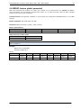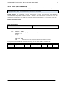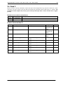
1
MODULE FOR STEPPER MOTORS MODULE Firmware Version V1.27 TMCL™ FIRMWARE MANUAL + + TMCM-1140 1-Axis Stepper Controller / Driver 2 A / 24 V sensOstep™ Encoder USB, RS485, and CAN + UNIQUE FEATURES: TRINAMIC Motion Control GmbH & Co. KG Hamburg, Germany www.trinamic.com + TMCM-1140 TMCL Firmware V1.27 Manual (Rev. 1.04 / 2015-JAN-05) Table of Contents 1 2 Features........................................................................................................................................................................... 4 Putting the Module into Operation ........................................................................................................................ 6 2.1 Basic Set-Up .......................................................................................................................................................... 6 2.1.1 Start the TMCL-IDE Software Development Environment ................................................................. 8 2.2 Using TMCL Direct Mode .................................................................................................................................... 9 2.2.1 Important Motor Settings ......................................................................................................................... 10 2.3 Testing with a Simple TMCL Program ......................................................................................................... 11 3 TMCL and the TMCL-IDE: Introduction ................................................................................................................. 12 3.1 Binary Command Format ................................................................................................................................ 12 3.1.1 Checksum Calculation ................................................................................................................................ 13 3.2 Reply Format ....................................................................................................................................................... 13 3.2.1 Status Codes ................................................................................................................................................. 14 3.3 Standalone Applications .................................................................................................................................. 14 3.4 TMCL Command Overview .............................................................................................................................. 15 3.4.1 TMCL Commands ......................................................................................................................................... 15 3.4.2 Commands Listed According to Subject Area .................................................................................... 16 3.5 The ASCII Interface ........................................................................................................................................... 20 3.5.1 Format of the Command Line ................................................................................................................. 20 3.5.2 Format of a Reply ....................................................................................................................................... 20 3.5.3 Configuring the ASCII Interface ............................................................................................................. 21 3.6 Commands ........................................................................................................................................................... 22 3.6.1 ROR (rotate right) ....................................................................................................................................... 22 3.6.2 ROL (rotate left) ........................................................................................................................................... 23 3.6.3 MST (motor stop)......................................................................................................................................... 24 3.6.4 MVP (move to position) ............................................................................................................................ 25 3.6.5 SAP (set axis parameter) ........................................................................................................................... 27 3.6.6 GAP (get axis parameter) .......................................................................................................................... 28 3.6.7 STAP (store axis parameter) ..................................................................................................................... 29 3.6.8 RSAP (restore axis parameter) ................................................................................................................. 30 3.6.9 SGP (set global parameter) ...................................................................................................................... 31 3.6.10 GGP (get global parameter)...................................................................................................................... 32 3.6.11 STGP (store global parameter) ................................................................................................................ 33 3.6.12 RSGP (restore global parameter) ............................................................................................................ 34 3.6.13 RFS (reference search) ................................................................................................................................ 35 3.6.14 SIO (set input / output) ............................................................................................................................. 36 3.6.15 GIO (get input /output) ............................................................................................................................. 38 3.6.16 CALC (calculate) ............................................................................................................................................ 40 3.6.17 COMP (compare)........................................................................................................................................... 41 3.6.18 JC (jump conditional) ................................................................................................................................. 42 3.6.19 JA (jump always) ......................................................................................................................................... 43 3.6.20 CSUB (call subroutine) ............................................................................................................................... 44 3.6.21 RSUB (return from subroutine) ................................................................................................................ 45 3.6.22 WAIT (wait for an event to occur) ......................................................................................................... 46 3.6.23 STOP (stop TMCL program execution) ................................................................................................... 47 3.6.24 SCO (set coordinate) ................................................................................................................................... 48 3.6.25 GCO (get coordinate) .................................................................................................................................. 49 3.6.26 CCO (capture coordinate) .......................................................................................................................... 50 3.6.27 ACO (accu to coordinate) .......................................................................................................................... 51 3.6.28 CALCX (calculate using the X register) .................................................................................................. 52 3.6.29 AAP (accumulator to axis parameter) .................................................................................................... 53 3.6.30 AGP (accumulator to global parameter) ............................................................................................... 54 3.6.31 CLE (clear error flags) ................................................................................................................................. 55 3.6.32 VECT (set interrupt vector) ........................................................................................................................ 56 3.6.33 EI (enable interrupt) ................................................................................................................................... 57 3.6.34 DI (disable interrupt) .................................................................................................................................. 58 3.6.35 RETI (return from interrupt) ..................................................................................................................... 59 www.trinamic.com 2 TMCM-1140 TMCL Firmware V1.27 Manual (Rev. 1.04 / 2015-JAN-05) 4 5 6 7 8 9 3.6.36 Customer Specific TMCL Command Extension (UF0… UF7 / User Function) ............................... 60 3.6.37 Request Target Position Reached Event ............................................................................................... 60 3.6.38 TMCL Control Functions ............................................................................................................................. 61 Axis Parameters .......................................................................................................................................................... 63 4.1 stallGuard2 ........................................................................................................................................................... 70 4.2 coolStep Related Axis Parameters ................................................................................................................ 70 4.3 Reference Search ............................................................................................................................................... 72 4.3.1 Reference Search Modes (Axis Parameter 193) ................................................................................... 73 4.4 Changing the Prescaler Value of an Encoder ............................................................................................ 76 Global Parameters ...................................................................................................................................................... 78 5.1 Bank 0 ................................................................................................................................................................... 78 5.2 Bank 1 ................................................................................................................................................................... 81 5.3 Bank 2 ................................................................................................................................................................... 81 5.4 Bank 3 ................................................................................................................................................................... 82 TMCL Programming Techniques and Structure ................................................................................................. 83 6.1 Initialization ........................................................................................................................................................ 83 6.2 Main Loop ............................................................................................................................................................ 83 6.3 Using Symbolic Constants .............................................................................................................................. 83 6.4 Using Variables .................................................................................................................................................. 84 6.5 Using Subroutines ............................................................................................................................................. 84 6.6 Mixing Direct Mode and Standalone Mode ................................................................................................ 85 Life Support Policy ..................................................................................................................................................... 86 Revision History .......................................................................................................................................................... 87 8.1 Firmware Revision ............................................................................................................................................ 87 8.2 Document Revision ........................................................................................................................................... 87 References .................................................................................................................................................................... 88 www.trinamic.com 3 TMCM-1140 TMCL Firmware V1.27 Manual (Rev. 1.04 / 2015-JAN-05) 4 1 Features The TMCM-1140 is a single axis controller/driver module for 2-phase bipolar stepper motors with state of the art feature set. It is highly integrated, offers a convenient handling and can be used in many decentralized applications. The module can be mounted on the back of NEMA 17 (42mm flange size) stepper motors and has been designed for coil currents up to 2 A RMS and 24 V DC supply voltage. With its high energy efficiency from TRINAMIC’s coolStep™ technology cost for power consumption is kept down. The TMCL™ firmware allows for both, standalone operation and direct mode. MAIN CHARACTERISTICS Motion controller Motion profile calculation in real-time On the fly alteration of motor parameters (e.g. position, velocity, acceleration) High performance microcontroller for overall system control and serial communication protocol handling Bipolar stepper motor driver Up to 256 microsteps per full step High-efficient operation, low power dissipation Dynamic current control Integrated protection stallGuard2 feature for stall detection coolStep feature for reduced power consumption and heat dissipation Encoder sensOstep magnetic encoder (1024 increments per rotation) e.g. for step-loss detection under all operating conditions and positioning supervision Interfaces RS485 2-wire communication interface CAN 2.0B communication interface USB full speed (12Mbit/s) device interface 4 multipurpose inputs: 3x general-purpose digital inputs (Alternate functions: STOP_L / STOP_R / HOME switch inputs or A/B/N encoder input) 1x dedicated analog input 2 general purpose outputs 1x open-drain 1A max. 1x +5V supply output (can be switched on/off in software) Software TMCL: standalone operation or remote controlled operation, program memory (non volatile) for up to 2048 TMCL commands, and PC-based application development software TMCL-IDE available for free. Electrical and mechanical data Supply voltage: +24 V DC nominal (9… 28 V DC) Motor current: up to 2 A RMS / 2.8 A peak (programmable) Refer to separate Hardware Manual, too. www.trinamic.com TMCM-1140 TMCL Firmware V1.27 Manual (Rev. 1.04 / 2015-JAN-05) 5 TRINAMICS UNIQUE FEATURES – EASY TO USE WITH TMCL stallGuard2™ stallGuard2 is a high-precision sensorless load measurement using the back EMF on the coils. It can be used for stall detection as well as other uses at loads below those which stall the motor. The stallGuard2 measurement value changes linearly over a wide range of load, velocity, and current settings. At maximum motor load, the value goes to zero or near to zero. This is the most energy-efficient point of operation for the motor. Load [Nm] stallGuard2 Initial stallGuard2 (SG) value: 100% Max. load stallGuard2 (SG) value: 0 Maximum load reached. Motor close to stall. Motor stalls Figure 1.1 stallGuard2 load measurement SG as a function of load coolStep™ coolStep is a load-adaptive automatic current scaling based on the load measurement via stallGuard2 adapting the required current to the load. Energy consumption can be reduced by as much as 75%. coolStep allows substantial energy savings, especially for motors which see varying loads or operate at a high duty cycle. Because a stepper motor application needs to work with a torque reserve of 30% to 50%, even a constant-load application allows significant energy savings because coolStep automatically enables torque reserve when required. Reducing power consumption keeps the system cooler, increases motor life, and allows reducing cost. 0,9 Efficiency with coolStep 0,8 Efficiency with 50% torque reserve 0,7 0,6 0,5 Efficiency 0,4 0,3 0,2 0,1 0 0 50 100 150 200 250 300 350 Velocity [RPM] Figure 1.2 Energy efficiency example with coolStep www.trinamic.com TMCM-1140 TMCL Firmware V1.27 Manual (Rev. 1.04 / 2015-JAN-05) 6 2 Putting the Module into Operation Here you can find basic information for putting your TMCM-1140 into operation. If you are already common with TRINAMICs modules you may skip this chapter. The things you need: TMCM-1140 Interface (RS485/CAN/USB) suitable to your module with cables Nominal supply voltage +24V DC for your module TMCL-IDE program and PC Stepper motor PRECAUTIONS Do not connect or disconnect the TMCM-1140 while powered! Do not connect or disconnect the motor while powered! Do not exceed the maximum power supply voltage of 28 V DC! Note, that the module is not protected against reverse polarity! START WITH POWER SUPPLY OFF! 2.1 Basic Set-Up The following paragraph will guide you through the steps of connecting the unit and making first movements with the motor. CONNECTING THE MODULE USB Converter e.g. USB-2-485 B US Converter e.g. USB-2-X CAN Pin 6 CAN_L Pin 5 CAN_H Pin 1 GND 1 Power supply Pin 2 9… 28V DC Pin 1 GND Note, that the GND pin has to be used for power supply and for the interfaces also. Motor 1 Motor Figure 2.1: Starting up www.trinamic.com USB RS485 Pin 4 RS485Pin 3 RS485+ Pin 1 GND In/Out Interface RS48 5 CA N Serial USB interface TMCM-1140 TMCL Firmware V1.27 Manual (Rev. 1.04 / 2015-JAN-05) 1. 7 Connect power supply and choose your interface a) Connect CAN or RS485 and power supply CAN interface will be de-activated in case USB is connected due to internal sharing of hardware resources. Pin 1 2 3 4 5 6 Label GND VDD RS485+ RS485CAN_H CAN_L Description System and signal ground VDD (+9V…+28V) RS485 interface, diff. signal (non-inverting) RS485 interface, diff. signal (inverting) CAN interface, diff. signal (non-inverting) CAN interface, diff. signal (inverting) b) Connect USB interface (as alternative to CAN and RS485; use a normal USB cable) Download and install the file TMCM-1140.inf (www.trinamic.com). Pin 1 2 3 4 5 2. Description +5V power Data – Data + ground ground Connect In/Out connector If you like to work with the GPIOs or switches, use the In/Out connector. Pin 1 2 Label GND VDD 3 OUT_1 4 OUT_0 5 AIN_0 6 7 8 3. Label VBUS DD+ ID GND IN_0, STOP_L, ENC_A IN_1, STOP_R, ENC_B IN_2, HOME, ENC_N Description System and signal ground VDD, connected to VDD pin of the power and communication connector Open-drain output (max. 1A) Integrated freewheeling diode to VDD +5V supply output (max. 100mA) Can be switched on/off in software Dedicated analog input, Input voltage range: 0..+10V Resolution: 12bit (0..4095) General purpose digital input (+24V compatible) Alternate function 1: left stop switch input Alternate function 2: external incremental encoder channel A input General purpose digital input (+24V compatible) Alternate function 1: right stop switch input Alternate function 2: external incremental encoder channel B input General purpose digital input (+24V compatible) Alternate function 1: home switch input Alternate function 2: external incremental encoder index / zero channel input Connect the motor Pin 1 2 3 4 Label OB2 OB1 OA2 OA1 www.trinamic.com Description Pin 2 of motor Pin 1 of motor Pin 2 of motor Pin 1 of motor coil coil coil coil B B A A TMCM-1140 TMCL Firmware V1.27 Manual (Rev. 1.04 / 2015-JAN-05) 4. Switch ON the power supply Turn power ON. The green LED for power lights up and the motor is powered but in standstill now. If this does not occur, switch power OFF and check your connections as well as the power supply. 2.1.1 Start the TMCL-IDE Software Development Environment The TMCL-IDE is available on www.trinamic.com. Installing the TMCL-IDE: Make sure the COM port you intend to use is not blocked by another program. Open TMCL-IDE by clicking TMCL.exe. Choose Setup and Options and thereafter the Connection tab. Choose COM port and type with the parameters shown in Figure 2.2 (baud rate 9600). Click OK. USB interface If the file TMCM-1140.inf is installed correctly, the module will be identified automatically. Figure 2.2 Setup dialogue and connection tab of the TMCL-IDE. Please refer to the TMCL-IDE User Manual for more information (see www.TRINAMIC.com). www.trinamic.com 8 TMCM-1140 TMCL Firmware V1.27 Manual (Rev. 1.04 / 2015-JAN-05) 9 2.2 Using TMCL Direct Mode 1. Start TMCL Direct Mode. Direct Mode 2. If the communication is established the TMCM-1140 is automatically detected. If the module is not detected, please check all points above (cables, interface, power supply, COM port, baud rate). 3. Issue a command by choosing Instruction, Type (if necessary), Motor, and Value and click Execute to send it to the module. Examples: - ROR rotate right, motor 0, value 500 - MST motor stop, motor 0 -> Click Execute. The motor is rotating now. -> Click Execute. The motor stops now. Top right of the TMCL Direct Mode window is the button Copy to editor. Click here to copy the chosen command and create your own TMCL program. The command will be shown immediately on the editor. Note: Chapter 4 of this manual (axis parameters) includes a diagram which points out the coolStep related axis parameters and their functions. www.trinamic.com TMCM-1140 TMCL Firmware V1.27 Manual (Rev. 1.04 / 2015-JAN-05) 2.2.1 10 Important Motor Settings There are some axis parameters which have to be adjusted right in the beginning after installing your module. Please set the upper limiting values for the speed (axis parameter 4), the acceleration (axis parameter 5), and the current (axis parameter 6). Further set the standby current (axis parameter 7) and choose your microstep resolution with axis parameter 140. Please use the SAP (Set Axis Parameter) command for adjusting these values. The SAP command is described in paragraph 3.6.5. You can use the TMCL-IDE direct mode for easily configuring your module. Attention: The most important motor setting is the absolute maximum motor current setting, since too high values might cause motor damage! IMPORTANT AXIS PARAMETERS FOR MOTOR SETTING Number 4 Axis Parameter Maximum positioning speed 5 Maximum acceleration 6 Absolute max. current (CS / Current Scale) Description Should not exceed the physically highest possible value. Adjust the pulse divisor (axis parameter 154), if the speed value is very low (<50) or above the upper limit. The limit for acceleration (and deceleration). Changing this parameter requires re-calculation of the acceleration factor (no. 146) and the acceleration divisor (no. 137), which is done automatically. See TMC 429 datasheet for calculation of physical units. The maximum value is 255. This value means 100% of the maximum current of the module. The current adjustment is within the range 0… 255 and can be adjusted in 32 steps. 0… 7 8… 15 16… 23 24… 31 32… 39 40… 47 48… 55 56… 63 64… 71 72… 79 7 Standby current 140 Microstep resolution *1 Unit of acceleration: www.trinamic.com 79…87 88… 95 96… 103 104… 111 112… 119 120… 127 128… 135 136… 143 144… 151 152… 159 160… 168… 176… 184… 192… 200… 208… 216… 224… 232… 167 175 183 191 199 207 215 223 231 239 Range [Unit] 0… 2047 0… 2047*1 0… 255 240… 247 248… 255 The most important motor setting, since too high values might cause motor damage! The current limit two seconds after the motor has 0… 255 stopped. 0 1 2 3 4 5 6 7 8 full step half step 4 microsteps 8 microsteps 16 microsteps 32 microsteps 64 microsteps 128 microsteps 256 microsteps 0… 8 TMCM-1140 TMCL Firmware V1.27 Manual (Rev. 1.04 / 2015-JAN-05) 2.3 Testing with a Simple TMCL Program Type in the following program: Loop: ROL 0, 500 WAIT TICKS, 0, 500 MST 0 ROR 0, 500 WAIT TICKS, 0, 500 MST 0 //Rotate motor 0 with speed 10000 SAP 4, 0, 500 SAP 5, 0, 50 MVP ABS, 0, 10000 WAIT POS, 0, 0 MVP ABS, 0, -10000 WAIT POS, 0, 0 JA Loop //Set max. Velocity //Set max. Acceleration //Move to Position 10000 //Wait until position reached //Move to Position -10000 //Wait until position reached //Infinite Loop //Rotate motor 0 with 50000 Assemble Stop Download 1. 2. 3. 4. Run Click the Assemble icon to convert the TMCL program into binary code. Then download the program to the TMCM-1140 module by clicking the Download icon. Click the Run icon. The desired program will be executed. Click the Stop button to stop the program. www.trinamic.com 11 TMCM-1140 TMCL Firmware V1.27 Manual (Rev. 1.04 / 2015-JAN-05) 12 3 TMCL and the TMCL-IDE: Introduction As with most TRINAMIC modules the software running on the microprocessor of the TMCM-1140 consists of two parts, a boot loader and the firmware itself. Whereas the boot loader is installed during production and testing at TRINAMIC and remains untouched throughout the whole lifetime, the firmware can be updated by the user. New versions can be downloaded free of charge from the TRINAMIC website (http://www.trinamic.com). The TMCM-1140 supports TMCL direct mode (binary commands) and standalone TMCL program execution. You can store up to 2048 TMCL instructions on it. In direct mode and most cases the TMCL communication over RS485, CAN, or USB follows a strict master/slave relationship. That is, a host computer (e.g. PC/PLC) acting as the interface bus master will send a command to the TMCM-1140. The TMCL interpreter on the module will then interpret this command, do the initialization of the motion controller, read inputs and write outputs or whatever is necessary according to the specified command. As soon as this step has been done, the module will send a reply back over RS485/CAN/USB to the bus master. Only then should the master transfer the next command. Normally, the module will just switch to transmission and occupy the bus for a reply, otherwise it will stay in receive mode. It will not send any data over the interface without receiving a command first. This way, any collision on the bus will be avoided when there are more than two nodes connected to a single bus. The Trinamic Motion Control Language [TMCL] provides a set of structured motion control commands. Every motion control command can be given by a host computer or can be stored in an EEPROM on the TMCM module to form programs that run standalone on the module. For this purpose there are not only motion control commands but also commands to control the program structure (like conditional jumps, compare and calculating). Every command has a binary representation and a mnemonic. The binary format is used to send commands from the host to a module in direct mode, whereas the mnemonic format is used for easy usage of the commands when developing standalone TMCL applications using the TMCL-IDE (IDE means Integrated Development Environment). There is also a set of configuration variables for the axis and for global parameters which allow individual configuration of nearly every function of a module. This manual gives a detailed description of all TMCL commands and their usage. 3.1 Binary Command Format Every command has a mnemonic and a binary representation. When commands are sent from a host to a module, the binary format has to be used. Every command consists of a one-byte command field, a onebyte type field, a one-byte motor/bank field and a four-byte value field. So the binary representation of a command always has seven bytes. When a command is to be sent via RS485 or USB interface, it has to be enclosed by an address byte at the beginning and a checksum byte at the end. In this case it consists of nine bytes. This is different when communicating is via the CAN bus. Address and checksum are included in the CAN standard and do not have to be supplied by the user. The binary command format for R485/USB is as follows: Bytes 1 1 1 1 4 1 - Meaning Module address Command number Type number Motor or Bank number Value (MSB first!) Checksum The checksum is calculated by adding up all the other bytes using an 8-bit addition. When using CAN bus, just leave out the first byte (module address) and the last byte (checksum). www.trinamic.com TMCM-1140 TMCL Firmware V1.27 Manual (Rev. 1.04 / 2015-JAN-05) 3.1.1 13 Checksum Calculation As mentioned above, the checksum is calculated by adding up all bytes (including the module address byte) using 8-bit addition. Here are two examples to show how to do this: in C: unsigned char i, Checksum; unsigned char Command[9]; //Set the “Command” array to the desired command Checksum = Command[0]; for(i=1; i<8; i++) Checksum+=Command[i]; Command[8]=Checksum; //insert checksum as last byte of the command //Now, send it to the module in Delphi: var i, Checksum: byte; Command: array[0..8] of byte; //Set the “Command” array to the desired command //Calculate the Checksum: Checksum:=Command[0]; for i:=1 to 7 do Checksum:=Checksum+Command[i]; Command[8]:=Checksum; //Now, send the “Command” array (9 bytes) to the module 3.2 Reply Format Every time a command has been sent to a module, the module sends a reply. The reply format for RS485/ /USB is as follows: Bytes 1 1 1 1 4 1 - Meaning Reply address Module address Status (e.g. 100 means no error) Command number Value (MSB first!) Checksum The checksum is also calculated by adding up all the other bytes using an 8-bit addition. When using CAN bus, just leave out the first byte (module address) and the last byte (checksum). Do not send the next command before you have received the reply! www.trinamic.com TMCM-1140 TMCL Firmware V1.27 Manual (Rev. 1.04 / 2015-JAN-05) 3.2.1 14 Status Codes The reply contains a status code. The status code can have one of the following values: Code 100 101 1 2 3 4 5 6 Meaning Successfully executed, no error Command loaded into TMCL program EEPROM Wrong checksum Invalid command Wrong type Invalid value Configuration EEPROM locked Command not available 3.3 Standalone Applications The module is equipped with a TMCL memory for storing TMCL applications. You can use TMCL-IDE for developing standalone TMCL applications. You can download a program into the EEPROM and afterwards it will run on the module. The TMCL-IDE contains an editor and the TMCL assembler where the commands can be entered using their mnemonic format. They will be assembled automatically into their binary representations. Afterwards this code can be downloaded into the module to be executed there. www.trinamic.com TMCM-1140 TMCL Firmware V1.27 Manual (Rev. 1.04 / 2015-JAN-05) 15 3.4 TMCL Command Overview In this section a short overview of the TMCL commands is given. 3.4.1 TMCL Commands Command ROR ROL MST MVP Number 1 2 3 4 SAP 5 Parameter <motor number>, <velocity> <motor number>, <velocity> <motor number> ABS|REL|COORD, <motor number>, <position|offset> <parameter>, <motor number>, <value> GAP 6 <parameter>, <motor number> STAP 7 <parameter>, <motor number> RSAP SGP 8 9 <parameter>, <motor number> <parameter>, <bank number>, value GGP 10 <parameter>, <bank number> STGP 11 <parameter>, <bank number> RSGP 12 <parameter>, <bank number> RFS SIO GIO CALC COMP JC JA CSUB RSUB EI DI WAIT STOP SCO 13 14 15 19 20 21 22 23 24 25 26 27 28 30 START|STOP|STATUS, <motor number> <port number>, <bank number>, <value> <port number>, <bank number> <operation>, <value> <value> <condition>, <jump address> <jump address> <subroutine address> GCO CCO CALCX AAP AGP VECT RETI ACO 31 32 33 34 35 37 38 39 www.trinamic.com <interrupt number> <interrupt number> <condition>, <motor number>, <ticks> <coordinate number>, <motor number>, <position> <coordinate number>, <motor number> <coordinate number>, <motor number> <operation> <parameter>, <motor number> <parameter>, <bank number> <interrupt number>, <label> <coordinate number>, <motor number> Description Rotate right with specified velocity Rotate left with specified velocity Stop motor movement Move to position (absolute or relative) Set axis parameter (motion control specific settings) Get axis parameter (read out motion control specific settings) Store axis parameter permanently (non volatile) Restore axis parameter Set global parameter (module specific settings e.g. communication settings or TMCL™ user variables) Get global parameter (read out module specific settings e.g. communication settings or TMCL™ user variables) Store global parameter (TMCL™ user variables only) Restore global parameter (TMCL™ user variable only) Reference search Set digital output to specified value Get value of analogue/digital input Process accumulator & value Compare accumulator <-> value Jump conditional Jump absolute Call subroutine Return from subroutine Enable interrupt Disable interrupt Wait with further program execution Stop program execution Set coordinate Get coordinate Capture coordinate Process accumulator & X-register Accumulator to axis parameter Accumulator to global parameter Set interrupt vector Return from interrupt Accu to coordinate TMCM-1140 TMCL Firmware V1.27 Manual (Rev. 1.04 / 2015-JAN-05) 3.4.2 16 Commands Listed According to Subject Area 3.4.2.1 Motion Commands These commands control the motion of the motor. They are the most important commands and can be used in direct mode or in standalone mode. Mnemonic ROL ROR MVP MST RFS SCO CCO GCO Command number 2 1 4 3 13 30 32 31 Meaning Rotate left Rotate right Move to position Motor stop Reference search Store coordinate Capture coordinate Get coordinate 3.4.2.2 Parameter Commands These commands are used to set, read and store axis parameters or global parameters. Axis parameters can be set independently for each axis, whereas global parameters control the behavior of the module itself. These commands can also be used in direct mode and in standalone mode. Mnemonic SAP GAP STAP RSAP SGP GGP STGP RSGP Command number 5 6 7 8 9 10 11 12 Meaning Set axis parameter Get axis parameter Store axis parameter into EEPROM Restore axis parameter from EEPROM Set global parameter Get global parameter Store global parameter into EEPROM Restore global parameter from EEPROM 3.4.2.3 Control Commands These commands are used to control the program flow (loops, conditions, jumps etc.). It does not make sense to use them in direct mode. They are intended for standalone mode only. Mnemonic JA JC COMP CSUB RSUB WAIT STOP Command number 22 21 20 23 24 27 28 Meaning Jump always Jump conditional Compare accumulator with constant value Call subroutine Return from subroutine Wait for a specified event End of a TMCL™ program 3.4.2.4 I/O Port Commands These commands control the external I/O ports and can be used in direct mode and in standalone mode. Mnemonic SIO GIO Command number 14 15 www.trinamic.com Meaning Set output Get input TMCM-1140 TMCL Firmware V1.27 Manual (Rev. 1.04 / 2015-JAN-05) 17 3.4.2.5 Calculation Commands These commands are intended to be used for calculations within TMCL applications. Although they could also be used in direct mode it does not make much sense to do so. Mnemonic CALC CALCX AAP AGP ACO Command number 19 33 34 35 39 Meaning Calculate using the accumulator and a constant value Calculate using the accumulator and the X register Copy accumulator to an axis parameter Copy accumulator to a global parameter Copy accu to coordinate For calculating purposes there is an accumulator (or accu or A register) and an X register. When executed in a TMCL program (in standalone mode), all TMCL commands that read a value store the result in the accumulator. The X register can be used as an additional memory when doing calculations. It can be loaded from the accumulator. When a command that reads a value is executed in direct mode the accumulator will not be affected. This means that while a TMCL program is running on the module (standalone mode), a host can still send commands like GAP and GGP to the module (e.g. to query the actual position of the motor) without affecting the flow of the TMCL™ program running on the module. 3.4.2.6 Interrupt Commands Due to some customer requests, interrupt processing has been introduced in the TMCL firmware for ARM based modules. Mnemonic EI DI VECT RETI 3.4.2.6.1 Command number 25 26 37 38 Meaning Enable interrupt Disable interrupt Set interrupt vector Return from interrupt Interrupt Types There are many different interrupts in TMCL, like timer interrupts, stop switch interrupts, position reached interrupts, and input pin change interrupts. Each of these interrupts has its own interrupt vector. Each interrupt vector is identified by its interrupt number. Please use the TMCL included file Interrupts.inc for symbolic constants of the interrupt numbers. 3.4.2.6.2 Interrupt Processing When an interrupt occurs and this interrupt is enabled and a valid interrupt vector has been defined for that interrupt, the normal TMCL program flow will be interrupted and the interrupt handling routine will be called. Before an interrupt handling routine gets called, the context of the normal program will be saved automatically (i.e. accumulator register, X register, TMCL flags). There is no interrupt nesting, i.e. all other interrupts are disabled while an interrupt handling routine is being executed. On return from an interrupt handling routine, the context of the normal program will automatically be restored and the execution of the normal program will be continued. www.trinamic.com TMCM-1140 TMCL Firmware V1.27 Manual (Rev. 1.04 / 2015-JAN-05) 3.4.2.6.3 18 Interrupt Vectors The following table shows all interrupt vectors that can be used. Interrupt number 0 1 2 3 15 21 27 28 39 40 41 42 255 3.4.2.6.4 Interrupt type Timer 0 Timer 1 Timer 2 (Target) position reached Stall (stallGuard2) Deviation Stop left Stop right IN_0 change IN_1 change IN_2 change IN_3 change Global interrupts Further Configuration of Interrupts Some interrupts need further configuration (e.g. the timer interval of a timer interrupt). This can be done using SGP commands with parameter bank 3 (SGP <type>, 3, <value>). Please refer to the SGP command (paragraph 3.6.9) for further information about that. 3.4.2.6.5 Using Interrupts in TMCL For using an interrupt proceed as follows: - Define an interrupt handling routine using the VECT command. If necessary, configure the interrupt using an SGP <type>, 3, <value> command. Enable the interrupt using an EI <interrupt> command. Globally enable interrupts using an EI 255 command. An interrupt handling routine must always end with a RETI command EXAMPLE FOR THE USE OF A TIMER INTERRUPT: VECT 0, Timer0Irq SGP 0, 3, 1000 EI 0 EI 255 //define the interrupt vector //configure the interrupt: set its period to 1000ms //enable this interrupt //globally switch on interrupt processing //Main program: toggles output 3, using a WAIT command for the delay Loop: SIO 3, 2, 1 WAIT TICKS, 0, 50 SIO 3, 2, 0 WAIT TICKS, 0, 50 JA Loop //Here is the interrupt handling routine Timer0Irq: GIO 0, 2 //check if OUT0 is high JC NZ, Out0Off //jump if not SIO 0, 2, 1 //switch OUT0 high RETI //end of interrupt Out0Off: SIO 0, 2, 0 //switch OUT0 low RETI //end of interrupt www.trinamic.com TMCM-1140 TMCL Firmware V1.27 Manual (Rev. 1.04 / 2015-JAN-05) 19 In the example above, the interrupt numbers are used directly. To make the program better readable use the provided include file Interrupts.inc. This file defines symbolic constants for all interrupt numbers which can be used in all interrupt commands. The beginning of the program above then looks like the following: #include Interrupts.inc VECT TI_TIMER0, Timer0Irq SGP TI_TIMER0, 3, 1000 EI TI_TIMER0 EI TI_GLOBAL Please also take a look at the other example programs. www.trinamic.com TMCM-1140 TMCL Firmware V1.27 Manual (Rev. 1.04 / 2015-JAN-05) 20 3.5 The ASCII Interface There is also an ASCII interface that can be used to communicate with the module and to send some commands as text strings. THE FOLLOWING COMMANDS CAN BE USED IN ASCII MODE: ROL, ROR, MST, MVP, SAP, GAP, STAP, RSAP, SGP, GGP, STGP, RSGP, RFS, SIO, GIO, SCO, GCO, CCO, UF0, UF1, UF2, UF3, UF4, UF5, UF6, and UF7. Note: Only direct mode commands can be entered in ASCII mode! SPECIAL COMMANDS WHICH ARE ONLY AVAILABLE IN ASCII MODE: - BIN: This command quits ASCII mode and returns to binary TMCL™ mode. RUN: This command can be used to start a TMCL™ program in memory. STOP: Stops a running TMCL™ application. ENTERING AND LEAVING ASCII MODE: 1. 2. 3. The ASCII command line interface is entered by sending the binary command 139 (enter ASCII mode). Afterwards the commands are entered as in the TMCL-IDE. For leaving the ASCII mode and re-enter the binary mode enter the command BIN. 3.5.1 Format of the Command Line As the first character, the address character has to be sent. The address character is A when the module address is 1, B for modules with address 2 and so on. After the address character there may be spaces (but this is not necessary). Then, send the command with its parameters. At the end of a command line a <CR> character has to be sent. EXAMPLES FOR VALID COMMAND LINES: AMVP ABS, 1, 50000 A MVP ABS, 1, 50000 AROL 2, 500 A MST 1 ABIN The command lines above address the module with address 1. To address e.g. module 3, use address character C instead of A. The last command line shown above will make the module return to binary mode. 3.5.2 Format of a Reply After executing the command the module sends back a reply in ASCII format. The - reply consists of: the address character of the host (host address that can be set in the module) the address character of the module the status code as a decimal number the return value of the command as a decimal number a <CR> character So, after sending AGAP 0, 1 the reply would be BA 100 –5000 if the actual position of axis 1 is –5000, the host address is set to 2 and the module address is 1. The value 100 is the status code 100 that means command successfully executed. www.trinamic.com TMCM-1140 TMCL Firmware V1.27 Manual (Rev. 1.04 / 2015-JAN-05) 21 3.5.3 Configuring the ASCII Interface The module can be configured so that it starts up either in binary mode or in ASCII mode. Global parameter 67 is used for this purpose (please see also chapter 5.1). Bit 0 determines the startup mode: if this bit is set, the module starts up in ASCII mode, else it will start up in binary mode (default). Bit 4 and Bit 5 determine how the characters that are entered are echoed back. Normally, both bits are set to zero. In this case every character that is entered is echoed back when the module is addressed. Character can also be erased using the backspace character (press the backspace key in a terminal program). When bit 4 is set and bit 5 is clear the characters that are entered are not echoed back immediately but the entire line will be echoed back after the <CR> character has been sent. When bit 5 is set and bit 4 is clear there will be no echo, only the reply will be sent. This may be useful in RS485 systems. www.trinamic.com TMCM-1140 TMCL Firmware V1.27 Manual (Rev. 1.04 / 2015-JAN-05) 22 3.6 Commands The module specific commands are explained in more detail on the following pages. They are listed according to their command number. 3.6.1 ROR (rotate right) With this command the motor will be instructed to rotate with a specified velocity in right direction (increasing the position counter). Internal function: First, velocity mode is selected. Then, the velocity value is transferred to axis parameter #0 (target velocity). The module is based on the TMC429 stepper motor controller and the TMC262 power driver. This makes possible choosing a velocity between 0 and 2047. Related commands: ROL, MST, SAP, GAP Mnemonic: ROR 0, <velocity> Binary representation: INSTRUCTION NO. 1 TYPE (don't care) MOT/BANK 0* VALUE <velocity> 0… 2047 *motor number is always O as only one motor is involved Reply in direct mode: STATUS 100 – OK VALUE (don't care) Example: Rotate right, velocity = 350 Mnemonic: ROR 0, 350 Binary: Byte Index Function Value (hex) 0 Targetaddress $01 www.trinamic.com 1 Instruction Number $01 2 Type $00 3 Motor/ Bank $00 4 Operand Byte3 $00 5 Operand Byte2 $00 6 Operand Byte1 $01 7 Operand Byte0 $5e TMCM-1140 TMCL Firmware V1.27 Manual (Rev. 1.04 / 2015-JAN-05) 3.6.2 23 ROL (rotate left) With this command the motor will be instructed to rotate with a specified velocity (opposite direction compared to ROR, decreasing the position counter). Internal function: First, velocity mode is selected. Then, the velocity value is transferred to axis parameter #0 (target velocity). The module is based on the TMC429 stepper motor controller and the TMC262 power driver. This makes possible choosing a velocity between 0 and 2047. Related commands: ROR, MST, SAP, GAP Mnemonic: ROL 0, <velocity> Binary representation: INSTRUCTION NO. 2 TYPE (don't care) MOT/BANK 0* VALUE <velocity> 0… 2047 *motor number is always O as only one motor is involved Reply in direct mode: STATUS 100 – OK VALUE (don't care) Example: Rotate left, velocity = 1200 Mnemonic: ROL 0, 1200 Binary: Byte Index Function Value (hex) 0 Targetaddress $01 www.trinamic.com 1 Instruction Number $02 2 Type $00 3 Motor/ Bank $00 4 Operand Byte3 $00 5 Operand Byte2 $00 6 Operand Byte1 $04 7 Operand Byte0 $b0 TMCM-1140 TMCL Firmware V1.27 Manual (Rev. 1.04 / 2015-JAN-05) 3.6.3 24 MST (motor stop) With this command the motor will be instructed to stop with a soft stop. Internal function: The axis parameter target velocity is set to zero. Related commands: ROL, ROR, SAP, GAP Mnemonic: MST 0 Binary representation: INSTRUCTION NO. 3 TYPE MOT/BANK VALUE (don't care) 0* (don't care) *motor number is always O as only one motor is involved Reply in direct mode: STATUS VALUE 100 – OK (don't care) Example: Stop motor Mnemonic: MST 0 Binary: Byte Index Function Value (hex) 0 Targetaddress $01 www.trinamic.com 1 Instruction Number $03 2 Type $00 3 Motor/ Bank $00 4 Operand Byte3 $00 5 Operand Byte2 $00 6 Operand Byte1 $00 7 Operand Byte0 $00 TMCM-1140 TMCL Firmware V1.27 Manual (Rev. 1.04 / 2015-JAN-05) 3.6.4 25 MVP (move to position) With this command the motor will be instructed to move to a specified relative or absolute position. It will use the acceleration/deceleration ramp and the positioning speed programmed into the unit. This command is non-blocking – that is, a reply will be sent immediately after command interpretation and initialization of the motion controller. Further commands may follow without waiting for the motor reaching its end position. The maximum velocity and acceleration are defined by axis parameters #4 and #5. The range of the MVP command is 32 bit signed (−2.147.483.648… +2.147.483.647). Positioning can be interrupted using MST, ROL or ROR commands. THREE OPERATION TYPES ARE AVAILABLE: - Moving to an absolute position in the range from −2.147.483.648… +2.147.483.647 (-231… 231-1). Starting a relative movement by means of an offset to the actual position. In this case, the new resulting position value must not exceed the above mentioned limits, too. Moving the motor to a (previously stored) coordinate (refer to SCO for details). Please note, that the distance between the actual position and the new one should not be more than 2.147.483.647 (231-1) microsteps. Otherwise the motor will run in the opposite direction in order to take the shorter distance. Internal function: A new position value is transferred to the axis parameter #2 target position”. Related commands: SAP, GAP, SCO, CCO, GCO, MST Mnemonic: MVP <ABS|REL|COORD>, 0, <position|offset|coordinate number> Binary representation: INSTRUCTION NO. 4 TYPE 0 ABS – absolute MOT/BANK 0* VALUE <position> 1 REL – relative 0 <offset> 2 COORD – coordinate 0 <coordinate number> (0… 20) *motor number is always O as only one motor is involved Reply in direct mode: STATUS 100 – OK VALUE (don't care) Example: Move motor to (absolute) position 90000 Mnemonic: MVP ABS, 0, 9000 Binary: Byte Index Function Value (hex) 0 Targetaddress $01 www.trinamic.com 1 Instruction Number $04 2 Type $00 3 Motor/ Bank $00 4 Operand Byte3 $00 5 Operand Byte2 $01 6 Operand Byte1 $5f 7 Operand Byte0 $90 TMCM-1140 TMCL Firmware V1.27 Manual (Rev. 1.04 / 2015-JAN-05) 26 Example: Move motor from current position 1000 steps backward (move relative –1000) Mnemonic: MVP REL, 0, -1000 Binary: Byte Index Function 0 Targetaddress Value (hex) $01 1 Instructio n Number $04 2 Type 3 Motor/ Bank 4 Operand Byte3 5 Operand Byte2 6 Operand Byte1 7 Operand Byte0 $01 $00 $ff $ff $fc $18 4 Operand Byte3 $00 5 Operand Byte2 $00 6 Operand Byte1 $00 7 Operand Byte0 $08 Example: Move motor to previously stored coordinate #8 Mnemonic: MVP COORD, 0, 8 Binary: Byte Index Function Value (hex) 0 Targetaddress $01 1 Instruction Number $04 2 Type $02 3 Motor/ Bank $00 When moving to a coordinate, the coordinate has to be set properly in advance with the help of the SCO, CCO or ACO command. www.trinamic.com TMCM-1140 TMCL Firmware V1.27 Manual (Rev. 1.04 / 2015-JAN-05) 3.6.5 27 SAP (set axis parameter) With this command most of the motion control parameters of the module can be specified. The settings will be stored in SRAM and therefore are volatile. That is, information will be lost after power off. Please use command STAP (store axis parameter) in order to store any setting permanently. For a table with parameters and values which can be used together with this command please refer to chapter 4. Internal function: The parameter format is converted ignoring leading zeros (or ones for negative values). The parameter is transferred to the correct position in the appropriate device. Related commands: GAP, STAP, RSAP, AAP Mnemonic: SAP <parameter number>, 0, <value> Binary representation: INSTRUCTION NO. 5 TYPE MOT/BANK VALUE <parameter number> 0* <value> *motor number is always O as only one motor is involved Reply in direct mode: STATUS 100 – OK VALUE (don't care) Example: Set the absolute maximum current of motor to 200mA Mnemonic: SAP 6, 0, 200 Binary: Byte Index Function Value (hex) 0 Targetaddress $01 www.trinamic.com 1 Instruction Number $05 2 Type $06 3 Motor/ Bank $00 4 Operand Byte3 $00 5 Operand Byte2 $00 6 Operand Byte1 $00 7 Operand Byte0 $c8 TMCM-1140 TMCL Firmware V1.27 Manual (Rev. 1.04 / 2015-JAN-05) 3.6.6 28 GAP (get axis parameter) Most parameters of the TMCM-1140 can be adjusted individually for the axis. With this parameter they can be read out. In standalone mode the requested value is also transferred to the accumulator register for further processing purposes (such as conditioned jumps). In direct mode the value read is only output in the value field of the reply (without affecting the accumulator). For a table with parameters and values which can be used together with this command please refer to chapter 4. Internal function: The parameter is read out of the correct position in the appropriate device. The parameter format is converted adding leading zeros (or ones for negative values). Related commands: SAP, STAP, AAP, RSAP Mnemonic: GAP <parameter number>, 0 Binary representation: INSTRUCTION NO. 6 TYPE <parameter number> MOT/BANK 0* VALUE (don't care) *motor number is always O as only one motor is involved Reply in direct mode: STATUS 100 – OK VALUE (don't care) Example: Get the actual position of motor Mnemonic: GAP 0, 1 Binary: Byte Index 0 1 2 Function Target- Instruction Type address Number Value (hex) $01 $06 $01 Reply: Byte Index Function Value (hex) 0 Hostaddress $02 1 Targetaddress $01 status=no error, position=711 www.trinamic.com 2 Status $64 3 Motor/ Bank $00 4 Operand Byte3 $00 5 Operand Byte2 $00 6 Operand Byte1 $00 7 Operand Byte0 $00 3 Instructio n $06 4 Operand Byte3 $00 5 Operand Byte2 $00 6 Operand Byte1 $02 7 Operand Byte0 $c7 TMCM-1140 TMCL Firmware V1.27 Manual (Rev. 1.04 / 2015-JAN-05) 3.6.7 29 STAP (store axis parameter) An axis parameter previously set with a Set Axis Parameter command (SAP) will be stored permanent. Most parameters are automatically restored after power up (refer to axis parameter list in chapter 4). For a table with parameters and values which can be used together with this command please refer to chapter 4. Internal function: An axis parameter value stored in SRAM will be transferred to EEPROM and loaded from EEPORM after next power up. Related commands: SAP, RSAP, GAP, AAP Mnemonic: STAP <parameter number>, 0 Binary representation: INSTRUCTION NO. 7 TYPE <parameter number> MOT/BANK 0*1 VALUE (don't care)*2 *1motor number is always O as only one motor is involved *2the value operand of this function has no effect. Instead, the currently used value (e.g. selected by SAP) is saved. Reply in direct mode: STATUS 100 – OK Parameter ranges: Parameter number s. chapter 4 VALUE (don't care) Motor number 0 Value s. chapter 4 Example: Store the maximum speed of motor Mnemonic: STAP 4, 0 Binary: Byte Index Function 0 Targetaddress Value (hex) $01 1 2 Instruction Type Number $07 $04 3 Motor/ Bank $00 4 Operand Byte3 $00 5 Operand Byte2 $00 6 Operand Byte1 $00 7 Operand Byte0 $00 Note: The STAP command will not have any effect when the configuration EEPROM is locked (refer to 5.1). In direct mode, the error code 5 (configuration EEPROM locked, see also section 3.2.1) will be returned in this case. www.trinamic.com TMCM-1140 TMCL Firmware V1.27 Manual (Rev. 1.04 / 2015-JAN-05) 3.6.8 30 RSAP (restore axis parameter) For all configuration-related axis parameters non-volatile memory locations are provided. By default, most parameters are automatically restored after power up (refer to axis parameter list in chapter 4). A single parameter that has been changed before can be reset by this instruction also. For a table with parameters and values which can be used together with this command please refer to chapter 4. Internal function: The specified parameter is copied from the configuration EEPROM memory to its RAM location. Relate commands: SAP, STAP, GAP, and AAP Mnemonic: RSAP <parameter number>, 0 Binary representation: INSTRUCTION NO. 8 TYPE MOT/BANK VALUE <parameter number> 0* (don't care) *motor number is always O as only one motor is involved Reply structure in direct mode: STATUS 100 – OK VALUE (don't care) Example: Restore the maximum current of motor Mnemonic: RSAP 6, 0 Binary: Byte Index Function Value (hex) 0 Targetaddress $01 www.trinamic.com 1 2 Instruction Type Number $08 $06 3 Motor/ Bank $00 4 Operand Byte3 $00 5 Operand Byte2 $00 6 Operand Byte1 $00 7 Operand Byte0 $00 TMCM-1140 TMCL Firmware V1.27 Manual (Rev. 1.04 / 2015-JAN-05) 3.6.9 31 SGP (set global parameter) With this command most of the module specific parameters not directly related to motion control can be specified and the TMCL user variables can be changed. Global parameters are related to the host interface, peripherals or application specific variables. The different groups of these parameters are organized in banks to allow a larger total number for future products. Currently, only bank 0 and 1 are used for global parameters, and bank 2 is used for user variables. Bank 3 is used for interrupt configuration. All module settings will automatically be stored non-volatile (internal EEPROM of the processor). The TMCL user variables will not be stored in the EEPROM automatically, but this can be done by using STGP commands. For a table with parameters and bank numbers which can be used together with this command please refer to chapter 5. Internal function: the parameter format is converted ignoring leading zeros (or ones for negative values). The parameter is transferred to the correct position in the appropriate (on board) device. Related commands: GGP, STGP, RSGP, AGP Mnemonic: SGP <parameter number>, <bank number>, <value> Binary representation: INSTRUCTION NO. 9 Reply in direct mode: STATUS 100 – OK TYPE MOT/BANK VALUE <parameter number> <bank number> <value> VALUE (don't care) Example: Set the serial address of the target device to 3 Mnemonic: SGP 66, 0, 3 Binary: Byte Index Function Value (hex) 0 Targetaddress $01 www.trinamic.com 1 2 Instruction Type Number $09 $42 3 Motor/ Bank $00 4 Operand Byte3 $00 5 Operand Byte2 $00 6 Operand Byte1 $00 7 Operand Byte0 $03 TMCM-1140 TMCL Firmware V1.27 Manual (Rev. 1.04 / 2015-JAN-05) 32 3.6.10 GGP (get global parameter) All global parameters can be read with this function. Global parameters are related to the host interface, peripherals or application specific variables. The different groups of these parameters are organized in banks to allow a larger total number for future products. Currently, only bank 0 and 1 are used for global parameters, and bank 2 is used for user variables. Bank 3 is used for interrupt configuration. For a table with parameters and bank numbers which can be used together with this command please refer to chapter 5. Internal function: The parameter is read out of the correct position in the appropriate device. The parameter format is converted adding leading zeros (or ones for negative values). Related commands: SGP, STGP, RSGP, AGP Mnemonic: GGP <parameter number>, <bank number> Binary representation: INSTRUCTION NO. 10 TYPE (see chapter 6) Reply in direct mode: STATUS 100 – OK VALUE (don't care) MOT/BANK <bank number> VALUE (don't care) Example: Get the serial address of the target device Mnemonic: GGP 66, 0 Binary: Byte Index Function Value (hex) Reply: Byte Index Function Value (hex) 0 1 Target- Instruction address Number $01 $0a 0 Hostaddress $02 1 Targetaddress $01 Status=no error, Value=1 www.trinamic.com 2 Type $42 2 Status $64 3 Motor/ Bank $00 4 Operand Byte3 $00 5 Operand Byte2 $00 6 Operand Byte1 $00 7 Operand Byte0 $00 3 Instructio n $0a 4 Operand Byte3 $00 5 Operand Byte2 $00 6 Operand Byte1 $00 7 Operand Byte0 $01 TMCM-1140 TMCL Firmware V1.27 Manual (Rev. 1.04 / 2015-JAN-05) 33 3.6.11 STGP (store global parameter) This command is used to store TMCL user variables permanently in the EEPROM of the module. Some global parameters are located in RAM memory, so without storing modifications are lost at power down. This instruction enables enduring storing. Most parameters are automatically restored after power up. For a table with parameters and bank numbers which can be used together with this command please refer to chapter 5. Internal function: The specified parameter is copied from its RAM location to the configuration EEPROM. Related commands: SGP, GGP, RSGP, AGP Mnemonic: STGP <parameter number>, <bank number> Binary representation: INSTRUCTION NO. 11 TYPE (see chapter 8) Reply in direct mode: STATUS VALUE 100 – OK MOT/BANK <bank number> (see chapter 5) VALUE (don't care) (don't care) Example: Store the user variable #42 Mnemonic: STGP 42, 2 Binary: Byte Index Function Value (hex) 0 1 Target- Instruction address Number $01 $0b www.trinamic.com 2 Type $2a 3 Motor/ Bank $02 4 Operand Byte3 $00 5 Operand Byte2 $00 6 Operand Byte1 $00 7 Operand Byte0 $00 TMCM-1140 TMCL Firmware V1.27 Manual (Rev. 1.04 / 2015-JAN-05) 34 3.6.12 RSGP (restore global parameter) With this command the contents of a TMCL user variable can be restored from the EEPROM. By default, most parameters are automatically restored after power up. A single parameter that has been changed before can be reset by this instruction. Internal function: the specified parameter is copied from the configuration EEPROM memory to its RAM location. Relate commands: SGP, STGP, GGP, and AGP Mnemonic: RSAP <parameter number>, <bank number> Binary representation: INSTRUCTION NO. 12 TYPE <parameter number> MOT/BANK <bank number> VALUE (don't care) Reply structure in direct mode: STATUS VALUE 100 – OK (don't care) For a table with parameters and bank numbers which can be used together with this command please refer to chapter 5. Example: Restore user variable #42 Mnemonic: RSGP 42, 2 Binary: Byte Index 0 1 Instruction Function TargetNumber address Value (hex) $01 $0c www.trinamic.com 2 Type $2a 3 Motor/ Bank $02 4 Operand Byte3 $00 5 Operand Byte2 $00 6 Operand Byte1 $00 7 Operand Byte0 $00 TMCM-1140 TMCL Firmware V1.27 Manual (Rev. 1.04 / 2015-JAN-05) 35 3.6.13 RFS (reference search) The TMCM-1140 has a built-in reference search algorithm which can be used. The reference search algorithm provides switching point calibration and supports up-to three switches. The status of the reference search can also be queried to see if it has already finished. (In a TMCL program it is better to use the WAIT command to wait for the end of a reference search.) Please see the appropriate parameters in the axis parameter table to configure the reference search algorithm to meet your needs (chapter 4 / 4.3). The reference search can be started, stopped, and the actual status of the reference search can be checked. Internal function: the reference search is implemented as a state machine, so interaction is possible during execution. Related commands: WAIT Mnemonic: RFS <START|STOP|STATUS>, <motor> Binary representation: INSTRUCTION NO. TYPE MOT/BANK 0 START – start ref. search 1 STOP – abort ref. search 2 STATUS – get status 13 VALUE 0 see below REPLY IN DIRECT MODE: When using type 0 (START) or 1 (STOP): STATUS VALUE 100 – OK don’t care When using type 2 (STATUS): STATUS 100 – OK VALUE 0 other values ref. search active no ref. search active Example: Start reference search of motor 0 Mnemonic: RFS START, 0 Binary: Byte Index Function Value (hex) 0 Targetaddress $01 1 Instruction Number $0d 2 Type $00 3 Motor/ Bank $00 4 Operand Byte3 $00 5 Operand Byte2 $00 With this module it is possible to use stall detection instead of a reference search. www.trinamic.com 6 Operand Byte1 $00 7 Operand Byte0 $00 TMCM-1140 TMCL Firmware V1.27 Manual (Rev. 1.04 / 2015-JAN-05) 36 3.6.14 SIO (set input / output) - SIO sets the status of the two general purpose digital outputs either to zero (0) or to one (1). Bank 2 is used for this purpose. SIO is used to switch the pull-up resistors for all digital inputs ON (1) and OFF (0). Bank 0 is used for this purpose. Internal function: the passed value is transferred to the specified output line. Related commands: GIO, WAIT Mnemonic: SIO <port number>, <bank number>, <value> Binary representation: INSTRUCTION NO. 14 TYPE <port number> MOT/BANK <bank number> VALUE <value> 0/1 Bank 2 is used for setting the status of the general digital output either to zero (0) or to one (1). Reply structure: STATUS VALUE 100 – OK don’t care Example: Activate OUT_1, supply +5V to external circuits (bank 2, output 1) Mnemonic: SIO 1, 2, 1 Binary: Byte Index Function Value (hex) 0 Targetaddress $01 1 2 Type Instruction Number $0e $07 3 Motor/ Bank $02 4 Operand Byte3 $00 5 Operand Byte2 $00 6 Operand Byte1 $00 7 Operand Byte0 $01 Multi-purpose I/O 8 1 Figure 3.1 I/O connector I/O PORTS USED FOR SIO AND COMMAND Pin 3 I/O port OUT_0 Command SIO 0, 2, <n> 4 OUT_1 SIO 1, 2, <n> www.trinamic.com 0 1 0 1 – – – – OUT_0 OUT_0 OUT_1 OUT_1 Range off / high impedance / floating pulled low (max. 1A) off / (weak) low via 10k pull-down resistor supplies +5V to external circuits (100mA load max.) TMCM-1140 TMCL Firmware V1.27 Manual (Rev. 1.04 / 2015-JAN-05) 37 ADDRESSING BOTH OUTPUT LINES WITH ONE SIO COMMAND - Set the type parameter to 255 and the bank parameter to 2. The value parameter must then be set to a value between 0… 255, where every bit represents one output line. Furthermore, the value can also be set to -1. In this special case, the contents of the lower 8 bits of the accumulator are copied to the output pins. Example: Set all output pins high. Mnemonic: SIO 255, 2, 3 THE FOLLOWING PROGRAM WILL SHOW THE STATES OF THE INPUT LINES ON THE OUTPUT LINES Loop: GIO 255, 0 SIO 255, 2,-1 JA Loop SPECIAL COMMAND FOR SWITCHING THE PULL-UP RESISTORS ON OR OFF FOR ALL THREE DIGITAL INPUTS AT ONCE Pin 6 7 8 I/O port IN_1 IN_2 IN_3 www.trinamic.com Command SIO 0, 0, <n> Range 1/0 0: OFF 1: ON TMCM-1140 TMCL Firmware V1.27 Manual (Rev. 1.04 / 2015-JAN-05) 38 3.6.15 GIO (get input /output) With this command the status of all general purpose inputs of the module can be read out. The function reads a digital or analog input port. Digital lines will read 0 and 1, while the ADC channels deliver their 12 bit result in the range of 0… 4095. GIO IN STANDALONE MODE In standalone mode the requested value is copied to the accumulator (accu) for further processing purposes such as conditioned jumps. GIO IN DIRECT MODE In direct mode the value is only output in the value field of the reply, without affecting the accumulator. The actual status of a digital output line can also be read. Internal function: the specified line is read. Related commands: SIO, WAIT Mnemonic: GIO <port number>, <bank number> Binary representation: INSTRUCTION NO. 15 TYPE <port number> Reply in direct mode: STATUS 100 – OK VALUE <status of the port> MOT/BANK <bank number> VALUE don’t care Example: Get the analog value of IN_0 Mnemonic: GIO 0, 1 Binary: Byte Index Function Value (hex) Reply: Byte Index Function Value (hex) 0 Targetaddress $01 1 Instruction Number $0f $00 0 Hostaddress $02 1 Targetaddress $01 2 Status Status = no error, value = 320 www.trinamic.com 2 Type $64 3 Motor/ Bank $01 4 Operand Byte3 $00 5 Operand Byte2 $00 6 Operand Byte1 $00 7 Operand Byte0 $00 3 Instructio n $0f 4 Operand Byte3 $00 5 Operand Byte2 $00 6 Operand Byte1 $01 7 Operand Byte0 $2e TMCM-1140 TMCL Firmware V1.27 Manual (Rev. 1.04 / 2015-JAN-05) 39 Multi-purpose I/O 8 1 Figure 3.2 I/O connector 3.6.15.1 I/O Bank 0 – Digital Inputs The analog input IN_0 can be read as digital or analog input at the same time. The analog value of IN_0 can be accessed in bank 1. Pin 5 6 7 8 I/O port IN_0 IN_1 IN_2 IN_3 Command GIO 0, 0 GIO 1, 0 GIO 2, 0 GIO 3, 0 Range 0/1 0/1 0/1 0/1 ENC_N CHANNEL READ-OUT COMMAND I/O port ENC_N channel input 0 off 1 active Command GIO 11, 0 READING ALL DIGITAL INPUTS WITH ONE GIO COMMAND - Set the type parameter to 255 and the bank parameter to 0. In this case the status of all digital input lines will be read to the lower eight bits of the accumulator. USE FOLLOWING PROGRAM TO REPRESENT THE STATES OF THE INPUT LINES ON THE OUTPUT LINES Loop: GIO 255, 0 SIO 255, 2,-1 JA Loop Note: IN_0 can be used as analog or digital input. 3.6.15.2 I/O Bank 1 – Analog Input The analog input IN_0 can be read as digital or analog input at the same time. The analog value of IN_0 can be accessed in bank 1. Pin 5 I/O port IN_0 Command GIO 0, 1 Range 0… 4095 READING OUT OPERATING VOLTAGE AND TEMPERATURE: I/O port Operating voltage [1/10 V] Temperature [˚C] www.trinamic.com Command GIO 8, 1 GIO 9, 1 TMCM-1140 TMCL Firmware V1.27 Manual (Rev. 1.04 / 2015-JAN-05) 40 3.6.15.3 I/O Bank 2 –States of Digital Outputs The states of the OUT lines (that have been set by SIO commands) can be read back using bank 2. Pin 3 4 I/O port OUT_0 OUT_1 Command GIO 0, 2, <n> GIO 1, 2, <n> Range 1/0 1/0 3.6.16 CALC (calculate) A value in the accumulator variable, previously read by a function such as GAP (get axis parameter) can be modified with this instruction. Nine different arithmetic functions can be chosen and one constant operand value must be specified. The result is written back to the accumulator, for further processing like comparisons or data transfer. Related commands: CALCX, COMP, JC, AAP, AGP, GAP, GGP Mnemonic: CALC <operation>, <value> where <op> is ADD, SUB, MUL, DIV, MOD, AND, OR, XOR, NOT or LOAD Binary representation: INSTRUCTION NO. 19 TYPE MOT/BANK VALUE 0 ADD – add to accu 1 SUB – subtract from accu 1 MUL – multiply accu by 1 DIV – divide accu by 1 MOD – modulo divide by 1 AND – logical and accu with 6 OR – logical or accu with 7 XOR – logical exor accu with 8 NOT – logical invert accu 9 LOAD – load operand to accu (don’t care) <operand> Example: Multiply accu by -5000 Mnemonic: CALC MUL, -5000 Binary: Byte Index Function Value (hex) 0 1 Target- Instruction address Number $01 $13 www.trinamic.com 2 Type $02 3 Motor/ Bank $00 4 Operand Byte3 $FF 5 Operand Byte2 $FF 6 Operand Byte1 $EC 7 Operand Byte0 $78 TMCM-1140 TMCL Firmware V1.27 Manual (Rev. 1.04 / 2015-JAN-05) 41 3.6.17 COMP (compare) The specified number is compared to the value in the accumulator register. The result of the comparison can for example be used by the conditional jump (JC) instruction. This command is intended for use in standalone operation only. The host address and the reply are only used to take the instruction to the TMCL program memory while the program loads down. It does not make sense to use this command in direct mode. Internal function: The specified value is compared to the internal accumulator, which holds the value of a preceding get or calculate instruction (see GAP/GGP/ CALC/CALCX). The internal arithmetic status flags are set according to the comparison result. Related commands: JC (jump conditional), GAP, GGP, CALC, CALCX Mnemonic: COMP <value> Binary representation: INSTRUCTION NO. 20 TYPE (don’t care) MOT/BANK (don’t care) VALUE <comparison value> Example: Jump to the address given by the label when the position of motor is greater than or equal to 1000. GAP 1, 2, 0 COMP 1000 JC GE, Label //get axis parameter, type: no. 1 (actual position), motor: 0, value: 0 (don’t care) //compare actual value to 1000 //jump, type: 5 greater/equal, the label must be defined somewhere else in the program Binary format of the COMP 1000 command: Byte Index 0 1 2 Instruction Function TargetType Number address Value (hex) $01 $14 $00 www.trinamic.com 3 Motor/ Bank $00 4 Operand Byte3 $00 5 Operand Byte2 $00 6 Operand Byte1 $03 7 Operand Byte0 $e8 TMCM-1140 TMCL Firmware V1.27 Manual (Rev. 1.04 / 2015-JAN-05) 42 3.6.18 JC (jump conditional) The JC instruction enables a conditional jump to a fixed address in the TMCL program memory, if the specified condition is met. The conditions refer to the result of a preceding comparison. Please refer to COMP instruction for examples. This function is for standalone operation only. The host address and the reply are only used to take the instruction to the TMCL program memory while the program loads down. It does not make sense to use this command in direct mode. See the host-only control functions for details. Internal function: the TMCL program counter is set to the passed value if the arithmetic status flags are in the appropriate state(s). Related commands: JA, COMP, WAIT, CLE Mnemonic: JC <condition>, <label> where <condition>=ZE|NZ|EQ|NE|GT|GE|LT|LE|ETO|EAL|EDV|EPO Binary representation: INSTRUCTION NO. 21 TYPE MOT/BANK VALUE zero NZ – not zero EQ – equal NE – not equal GT – greater GE – greater/equal 6 LT – lower 7 LE – lower/equal 8 ETO – time out error (don’t care) <jump address> 0 ZE – 1 1 1 1 1 Example: Jump to address given by the label when the position of motor is greater than or equal to 1000. GAP 1, 0, 0 //get axis parameter, type: no. 1 (actual position), motor: 0, value: 0 (don’t care) COMP 1000 //compare actual value to 1000 JC GE, Label //jump, type: 5 greater/equal … … Label: ROL 0, 1000 Binary format of JC GE, Label when Label is at address 10: Byte Index 0 1 2 3 Instruction Function TargetType Motor/ Number address Bank Value (hex) $01 $15 $05 $00 www.trinamic.com 4 Operand Byte3 $00 5 Operand Byte2 $00 6 Operand Byte1 $00 7 Operand Byte0 $0a TMCM-1140 TMCL Firmware V1.27 Manual (Rev. 1.04 / 2015-JAN-05) 43 3.6.19 JA (jump always) Jump to a fixed address in the TMCL program memory. This command is intended for standalone operation only. The host address and the reply are only used to take the instruction to the TMCL program memory while the program loads down. This command cannot be used in direct mode. Internal function: the TMCL program counter is set to the passed value. Related commands: JC, WAIT, CSUB Mnemonic: JA <Label> Binary representation: INSTRUCTION NO. 22 TYPE (don’t care) MOT/BANK (don’t care) VALUE <jump address> Example: An infinite loop in TMCL™ Loop: MVP ABS, 0, 10000 WAIT POS, 0, 0 MVP ABS, 0, 0 WAIT POS, 0, 0 JA Loop //Jump to the label Loop Binary format of JA Loop assuming that the label Loop is at address 20: Byte Index 0 1 2 3 4 5 Instruction Function TargetType Motor/ Operand Operand Number address Bank Byte3 Byte2 Value (hex) $01 $16 $00 $00 $00 $00 www.trinamic.com 6 Operand Byte1 $00 7 Operand Byte0 $14 TMCM-1140 TMCL Firmware V1.27 Manual (Rev. 1.04 / 2015-JAN-05) 44 3.6.20 CSUB (call subroutine) This function calls a subroutine in the TMCL program memory. It is intended for standalone operation only. The host address and the reply are only used to take the instruction to the TMCL program memory while the program loads down. This command cannot be used in direct mode. Internal function: The actual TMCL program counter value is saved to an internal stack, afterwards overwritten with the passed value. The number of entries in the internal stack is limited to 8. This also limits nesting of subroutine calls to 8. The command will be ignored if there is no more stack space left. Related commands: RSUB, JA Mnemonic: CSUB <Label> Binary representation: INSTRUCTION NO. 23 TYPE (don’t care) MOT/BANK (don’t care) VALUE <subroutine address> Example: Call a subroutine Loop: MVP ABS, 0, 10000 CSUB SubW //Save program counter and jump to label SubW MVP ABS, 0, 0 JA Loop SubW: WAIT POS, 0, 0 WAIT TICKS, 0, 50 RSUB //Continue with the command following the CSUB command Binary format of the CSUB SubW command assuming that the label SubW is at address 100: Byte Index 0 1 2 3 4 5 6 Instruction Function TargetType Motor/ Operand Operand Operand Number address Bank Byte3 Byte2 Byte1 Value (hex) $01 $17 $00 $00 $00 $00 $00 www.trinamic.com 7 Operand Byte0 $64 TMCM-1140 TMCL Firmware V1.27 Manual (Rev. 1.04 / 2015-JAN-05) 45 3.6.21 RSUB (return from subroutine) Return from a subroutine to the command after the CSUB command. This command is intended for use in standalone mode only. The host address and the reply are only used to take the instruction to the TMCL program memory while the program loads down. This command cannot be used in direct mode. Internal function: The TMCL program counter is set to the last value of the stack. The command will be ignored if the stack is empty. Related command: CSUB Mnemonic: RSUB Binary representation: INSTRUCTION NO. 24 TYPE (don’t care) MOT/BANK (don’t care) VALUE (don’t care) Example: please see the CSUB example (section 3.6.20). Binary format of RSUB: Byte Index 0 Function Targetaddress Value (hex) $01 www.trinamic.com 1 Instruction Number $18 2 Type $00 3 Motor/ Bank $00 4 Operand Byte3 $00 5 Operand Byte2 $00 6 Operand Byte1 $00 7 Operand Byte0 $00 TMCM-1140 TMCL Firmware V1.27 Manual (Rev. 1.04 / 2015-JAN-05) 46 3.6.22 WAIT (wait for an event to occur) This instruction interrupts the execution of the TMCL program until the specified condition is met. This command is intended for standalone operation only. The host address and the reply are only used to take the instruction to the TMCL program memory while the program loads down. This command cannot be used in direct mode. THERE ARE FIVE DIFFERENT WAIT CONDITIONS THAT CAN BE USED: - TICKS: Wait until the number of timer ticks specified by the <ticks> parameter has been reached. POS: Wait until the target position of the motor specified by the <motor> parameter has been reached. An optional timeout value (0 for no timeout) must be specified by the <ticks> parameter. REFSW: Wait until the reference switch of the motor specified by the <motor> parameter has been triggered. An optional timeout value (0 for no timeout) must be specified by the <ticks> parameter. LIMSW: Wait until a limit switch of the motor specified by the <motor> parameter has been triggered. An optional timeout value (0 for no timeout) must be specified by the <ticks> parameter. RFS: Wait until the reference search of the motor specified by the <motor> field has been reached. An optional timeout value (0 for no timeout) must be specified by the <ticks> parameter. The timeout flag (ETO) will be set after a timeout limit has been reached. You can then use a JC ETO command to check for such errors or clear the error using the CLE command. Internal function: The TMCL program counter is held until the specified condition is met. Related commands: JC, CLE Mnemonic: WAIT <condition>, 0, <ticks> where <condition> is TICKS|POS|REFSW|LIMSW|RFS Binary representation: INSTRUCTION NO. TYPE MOT/BANK 1 0 TICKS – timer ticks* 1 POS – target position reached 0 *2 2 REFSW – reference switch 27 don’t care 0 *2 0 *2 3 LIMSW – limit switch 4 RFS – reference search completed 0 *2 VALUE <no. of ticks*1> <no. of ticks*1 for 0 for no timeout <no. of ticks*1 for 0 for no timeout <no. of ticks*1 for 0 for no timeout <no. of ticks*1 for 0 for no timeout timeout>, timeout>, timeout>, timeout>, *1 one tick is 10 milliseconds (in standard firmware) *2 motor number is always O as only one motor is involved Example: Wait for motor to reach its target position, without timeout Mnemonic: WAIT POS, 0, 0 Binary: Byte Index Function Value (hex) 0 Targetaddress $01 www.trinamic.com 1 Instruction Number $1b 2 Type $01 3 Motor/ Bank $00 4 Operand Byte3 $00 5 Operand Byte2 $00 6 Operand Byte1 $00 7 Operand Byte0 $00 TMCM-1140 TMCL Firmware V1.27 Manual (Rev. 1.04 / 2015-JAN-05) 47 3.6.23 STOP (stop TMCL program execution) This function stops executing a TMCL program. The host address and the reply are only used to transfer the instruction to the TMCL program memory. This command should be placed at the end of every standalone TMCL program. It is not to be used in direct mode. Internal function: TMCL instruction fetching is stopped. Related commands: none Mnemonic: STOP Binary representation: INSTRUCTION NO. 28 TYPE (don’t care) MOT/BANK (don’t care) VALUE (don’t care) Example: Mnemonic: STOP Binary: Byte Index Function Value (hex) 0 Targetaddress $01 www.trinamic.com 1 Instruction Number $1c 2 Type $00 3 Motor/ Bank $00 4 Operand Byte3 $00 5 Operand Byte2 $00 6 Operand Byte1 $00 7 Operand Byte0 $00 TMCM-1140 TMCL Firmware V1.27 Manual (Rev. 1.04 / 2015-JAN-05) 48 3.6.24 SCO (set coordinate) Up to 20 position values (coordinates) can be stored for every axis for use with the MVP COORD command. This command sets a coordinate to a specified value. Depending on the global parameter 84, the coordinates are only stored in RAM or also stored in the EEPROM and copied back on startup (with the default setting the coordinates are stored in RAM only). Please note that the coordinate number 0 is always stored in RAM only. Internal function: the passed value is stored in the internal position array. Related commands: GCO, CCO, MVP Mnemonic: SCO <coordinate number>, 0, <position> Binary representation: INSTRUCTION NO. 30 TYPE <coordinate number> 0… 20 Reply in direct mode: STATUS 100 – OK MOT/BANK 0 VALUE <position> -231… +231 VALUE don’t care Example: Set coordinate #1 of motor to 1000 Mnemonic: SCO 1, 0, 1000 Binary: Byte Index Function Value (hex) 0 Targetaddress $01 1 Instruction Number $1e 2 Type $01 3 Motor/ Bank $00 4 Operand Byte3 $00 5 Operand Byte2 $00 6 Operand Byte1 $03 7 Operand Byte0 $e8 Note: Two special functions of this command have been introduced that make it possible to copy all coordinates or one selected coordinate to the EEPROM. THESE FUNCTIONS CAN BE ACCESSED USING THE FOLLOWING SPECIAL FORMS OF THE SCO COMMAND: SCO 0, 255, 0 SCO <coordinate number>, 255, 0 www.trinamic.com copies all coordinates (except coordinate number 0) from RAM to the EEPROM. copies the coordinate selected by <coordinate number> to the EEPROM. The coordinate number must be a value between 1 and 20. TMCM-1140 TMCL Firmware V1.27 Manual (Rev. 1.04 / 2015-JAN-05) 49 3.6.25 GCO (get coordinate) This command makes possible to read out a previously stored coordinate. In standalone mode the requested value is copied to the accumulator register for further processing purposes such as conditioned jumps. In direct mode, the value is only output in the value field of the reply, without affecting the accumulator. Depending on the global parameter 84, the coordinates are only stored in RAM or also stored in the EEPROM and copied back on startup (with the default setting the coordinates are stored in RAM, only). Please note that the coordinate number 0 is always stored in RAM, only. Internal function: the desired value is read out of the internal coordinate array, copied to the accumulator register and – in direct mode – returned in the value field of the reply. Related commands: SCO, CCO, MVP Mnemonic: GCO <coordinate number>, 0 Binary representation: INSTRUCTION NO. 31 TYPE MOT/BANK VALUE <coordinate number> 0… 20 0 don’t care Reply in direct mode: STATUS VALUE 100 – OK don’t care Example: Get motor value of coordinate 1 Mnemonic: GCO 1, 0 Binary: Byte Index Function Value (hex) Reply: Byte Index Function Value (hex) Value: 0 0 Targetaddress $01 Instruction Number 1 2 Type $1f $01 0 Targetaddress $02 1 Targetaddress $01 2 Status $64 3 Motor/ Bank $00 4 Operand Byte3 $00 5 Operand Byte2 $00 6 Operand Byte1 $00 7 Operand Byte0 $00 3 Instructio n $0a 4 Operand Byte3 $00 5 Operand Byte2 $00 6 Operand Byte1 $00 7 Operand Byte0 $00 Note: Two special functions of this command have been introduced that make it possible to copy all coordinates or one selected coordinate from the EEPROM to the RAM. THESE FUNCTIONS CAN BE ACCESSED USING THE FOLLOWING SPECIAL FORMS OF THE GCO COMMAND: GCO 0, 255, 0 GCO <coordinate number>, 255, 0 www.trinamic.com copies all coordinates (except coordinate number 0) from the EEPROM to the RAM. copies the coordinate selected by <coordinate number> from the EEPROM to the RAM. The coordinate number must be a value between 1 and 20. TMCM-1140 TMCL Firmware V1.27 Manual (Rev. 1.04 / 2015-JAN-05) 50 3.6.26 CCO (capture coordinate) The actual position of the axis is copied to the selected coordinate variable. Depending on the global parameter 84, the coordinates are only stored in RAM or also stored in the EEPROM and copied back on startup (with the default setting the coordinates are stored in RAM only). Please see the SCO and GCO commands on how to copy coordinates between RAM and EEPROM. Note, that the coordinate number 0 is always stored in RAM only. Internal function: the selected (24 bit) position values are written to the 20 by 3 bytes wide coordinate array. Related commands: SCO, GCO, MVP Mnemonic: CCO <coordinate number>, 0 Binary representation: INSTRUCTION NO. 32 TYPE MOT/BANK VALUE <coordinate number> 0… 20 0 don’t care Reply in direct mode: STATUS VALUE 100 – OK don’t care Example: Store current position of the axis 0 to coordinate 3 Mnemonic: CCO 3, 0 Binary: Byte Index Function Value (hex) 0 Targetaddress $01 www.trinamic.com 1 Instruction Number $20 2 Type $03 3 Motor/ Bank $00 4 Operand Byte3 $00 5 Operand Byte2 $00 6 Operand Byte1 $00 7 Operand Byte0 $00 TMCM-1140 TMCL Firmware V1.27 Manual (Rev. 1.04 / 2015-JAN-05) 51 3.6.27 ACO (accu to coordinate) With the ACO command the actual value of the accumulator is copied to a selected coordinate of the motor. Depending on the global parameter 84, the coordinates are only stored in RAM or also stored in the EEPROM and copied back on startup (with the default setting the coordinates are stored in RAM only). Please note also that the coordinate number 0 is always stored in RAM only. For Information about storing coordinates refer to the SCO command. Internal function: the actual value of the accumulator is stored in the internal position array. Related commands: GCO, CCO, MVP COORD, SCO Mnemonic: ACO <coordinate number>, 0 Binary representation: INSTRUCTION NO. 39 Reply in direct mode: STATUS 100 – OK TYPE <coordinate number> 0… 20 MOT/BANK 0 VALUE don’t care VALUE don’t care Example: Copy the actual value of the accumulator to coordinate 1 of motor 0 Mnemonic: ACO 1, 0 Binary: Byte Index Function Value (hex) 0 1 Target- Instruction address Number $01 $27 www.trinamic.com 2 Type $01 3 Motor/ Bank $00 4 Operand Byte3 $00 5 Operand Byte2 $00 6 Operand Byte1 $00 7 Operand Byte0 $00 TMCM-1140 TMCL Firmware V1.27 Manual (Rev. 1.04 / 2015-JAN-05) 52 3.6.28 CALCX (calculate using the X register) This instruction is very similar to CALC, but the second operand comes from the X register. The X register can be loaded with the LOAD or the SWAP type of this instruction. The result is written back to the accumulator for further processing like comparisons or data transfer. Related commands: CALC, COMP, JC, AAP, AGP Mnemonic: CALCX <operation> with <operation>=ADD|SUB|MUL|DIV|MOD|AND|OR|XOR|NOT|LOAD|SWAP Binary representation: INSTRUCTION NO. TYPE 33 0 ADD – add X register to accu 1 SUB – subtract X register from accu 1 MUL – multiply accu by X register 1 DIV – divide accu by X-register 1 MOD – modulo divide accu by xregister 1 AND – logical and accu with Xregister 6 OR – logical or accu with X-register 7 XOR – logical exor accu with X-register 8 NOT – logical invert X-register 9 LOAD – load accu to X-register 10 SWAP – swap accu with X-register Example: Multiply accu by X-register Mnemonic: CALCX MUL Binary: Byte Index 0 1 Instruction Function TargetNumber address Value (hex) $01 $21 www.trinamic.com 2 Type $02 3 Motor/ Bank $00 MOT/BANK (don’t care) 4 Operand Byte3 $00 5 Operand Byte2 $00 VALUE (don’t care) 6 Operand Byte1 $00 7 Operand Byte0 $00 TMCM-1140 TMCL Firmware V1.27 Manual (Rev. 1.04 / 2015-JAN-05) 53 3.6.29 AAP (accumulator to axis parameter) The content of the accumulator register is transferred to the specified axis parameter. For practical usage, the accumulator has to be loaded e.g. by a preceding GAP instruction. The accumulator may have been modified by the CALC or CALCX (calculate) instruction. For a table with parameters and values which can be used together with this command please refer to chapter 4. Related commands: AGP, SAP, GAP, SGP, GGP, CALC, CALCX Mnemonic: AAP <parameter number>, 0 Binary representation: INSTRUCTION NO. 34 TYPE <parameter number> MOT/BANK 0* VALUE <don’t care> * Motor number is always 0 as only one motor is involved Reply in direct mode: STATUS VALUE 100 – OK (don’t care) Example: Positioning motor by a potentiometer connected to the analogue input #0: Start: GIO 0,1 CALC MUL, 4 AAP 0,0 JA Start // // // // get value of analogue input line 0 multiply by 4 transfer result to target position of motor 0 jump back to start Binary format of the AAP 0,0 command: Byte Index 0 1 2 Instruction Function TargetType Number address Value (hex) $01 $22 $00 www.trinamic.com 3 Motor/ Bank $00 4 Operand Byte3 $00 5 Operand Byte2 $00 6 Operand Byte1 $00 7 Operand Byte0 $00 TMCM-1140 TMCL Firmware V1.27 Manual (Rev. 1.04 / 2015-JAN-05) 54 3.6.30 AGP (accumulator to global parameter) The content of the accumulator register is transferred to the specified global parameter. For practical usage, the accumulator has to be loaded e.g. by a preceding GAP instruction. The accumulator may have been modified by the CALC or CALCX (calculate) instruction. Note: The global parameters in bank 0 are EEPROM-only and thus should not be modified automatically by a standalone application. (See chapter 5 for a complete list of global parameters). Related commands: AAP, SGP, GGP, SAP, GAP Mnemonic: AGP <parameter number>, <bank number> Binary representation: INSTRUCTION NO. 35 TYPE MOT/BANK VALUE <parameter number> <bank number> (don’t care) Reply in direct mode: STATUS VALUE 100 – OK (don’t care) For a table with parameters and bank numbers which can be used together with this command please refer to chapter 5. Example: Copy accumulator to TMCL user variable #3 Mnemonic: AGP 3, 2 Binary: Byte Index Function Value (hex) 0 Targetaddress $01 www.trinamic.com 1 Instruction Number $23 2 Type $03 3 Motor/ Bank $02 4 Operand Byte3 $00 5 Operand Byte2 $00 6 Operand Byte1 $00 7 Operand Byte0 $00 TMCM-1140 TMCL Firmware V1.27 Manual (Rev. 1.04 / 2015-JAN-05) 55 3.6.31 CLE (clear error flags) This command clears the internal error flags. It is intended for use in standalone mode only and must not be used in direct mode. The - following error flags can be cleared by this command (determined by the <flag> parameter): ALL: clear all error flags. ETO: clear the timeout flag. EDV: clear the deviation flag Related commands: JC Mnemonic: CLE <flags> where <flags>=ALL|ETO|EDV|EPO Binary representation: INSTRUCTION NO. 36 TYPE MOT/BANK VALUE 0 – (ALL) all flags 1 – (ETO) timeout flag 3 – (EDV) deviation flag (don’t care) (don’t care) Example: Reset the timeout flag Mnemonic: CLE ETO Binary: Byte Index Function Value (hex) 0 Targetaddress $01 www.trinamic.com 1 Instruction Number $24 2 Type $01 3 Motor/ Bank $00 4 Operand Byte3 $00 5 Operand Byte2 $00 6 Operand Byte1 $00 7 Operand Byte0 $00 TMCM-1140 TMCL Firmware V1.27 Manual (Rev. 1.04 / 2015-JAN-05) 56 3.6.32 VECT (set interrupt vector) The VECT command defines an interrupt vector. It needs an interrupt number and a label as parameter (like in JA, JC and CSUB commands). This label must be the entry point of the interrupt handling routine. Related commands: EI, DI, RETI Mnemonic: VECT <interrupt number>, <label> Binary representation: INSTRUCTION NO. 37 TYPE <interrupt number> MOT/BANK don’t care VALUE <label> THE FOLLOWING TABLE SHOWS ALL INTERRUPT VECTORS THAT CAN BE USED: Interrupt number 0 1 2 3 15 21 27 28 39 40 41 42 Interrupt type Timer 0 Timer 1 Timer 2 (Target) position reached Stall (stallGuard2) Deviation Stop left Stop right IN_0 change IN_1 change IN_2 change IN_3 change Example: Define interrupt vector at target position 500 VECT 3, 500 Binary format of VECT: Byte Index 0 Function Targetaddress Value (hex) $01 www.trinamic.com 1 Instruction Number $25 2 Type $03 3 Motor/ Bank $00 4 Operand Byte3 $00 5 Operand Byte2 $00 6 Operand Byte1 $01 7 Operand Byte0 $F4 TMCM-1140 TMCL Firmware V1.27 Manual (Rev. 1.04 / 2015-JAN-05) 57 3.6.33 EI (enable interrupt) The EI command enables an interrupt. It needs the interrupt number as parameter. Interrupt number 255 globally enables interrupts. Related command: DI, VECT, RETI Mnemonic: EI <interrupt number> Binary representation: INSTRUCTION NO. 25 TYPE <interrupt number> MOT/BANK don’t care VALUE don’t care THE FOLLOWING TABLE SHOWS ALL INTERRUPT VECTORS THAT CAN BE USED: Interrupt number 0 1 2 3 15 21 27 28 39 40 41 42 Interrupt type Timer 0 Timer 1 Timer 2 (Target) position reached Stall (stallGuard2™) Deviation Stop left Stop right IN_0 change IN_1 change IN_2 change IN_3 change Examples: Enable interrupts globally EI, 255 Binary format of EI: Byte Index 0 1 Function Target- Instruction address Number Value (hex) $01 $19 2 Type $FF 3 Motor/ Bank $00 4 Operand Byte3 $00 5 Operand Byte2 $00 6 Operand Byte1 $00 7 Operand Byte0 $00 3 Motor/ Bank $00 4 Operand Byte3 $00 5 Operand Byte2 $00 6 Operand Byte1 $00 7 Operand Byte0 $00 Enable interrupt when target position reached EI, 3 Binary format of EI: Byte Index 0 1 Function Target- Instruction address Number Value (hex) $01 $19 www.trinamic.com 2 Type $03 TMCM-1140 TMCL Firmware V1.27 Manual (Rev. 1.04 / 2015-JAN-05) 58 3.6.34 DI (disable interrupt) The DI command disables an interrupt. It needs the interrupt number as parameter. Interrupt number 255 globally disables interrupts. Related command: EI, VECT, RETI Mnemonic: DI <interrupt number> Binary representation: INSTRUCTION NO. 26 TYPE <interrupt number> MOT/BANK don’t care VALUE don’t care THE FOLLOWING TABLE SHOWS ALL INTERRUPT VECTORS THAT CAN BE USED: Interrupt number 0 1 2 3 15 21 27 28 39 40 41 42 Interrupt type Timer 0 Timer 1 Timer 2 (Target) position reached Stall (stallGuard2™) Deviation Stop left Stop right IN_0 change IN_1 change IN_2 change IN_3 change Examples: Disable interrupts globally DI, 255 Binary format of DI: Byte Index 0 Function Targetaddress Value (hex) $01 1 Instruction Number $1A 2 Type $FF 3 Motor/ Bank $00 4 Operand Byte3 $00 5 Operand Byte2 $00 6 Operand Byte1 $00 7 Operand Byte0 $00 3 Motor/ Bank $00 4 Operand Byte3 $00 5 Operand Byte2 $00 6 Operand Byte1 $00 7 Operand Byte0 $00 Disable interrupt when target position reached DI, 3 Binary format of DI: Byte Index 0 Function Targetaddress Value (hex) $01 www.trinamic.com 1 Instruction Number $1A 2 Type $03 TMCM-1140 TMCL Firmware V1.27 Manual (Rev. 1.04 / 2015-JAN-05) 59 3.6.35 RETI (return from interrupt) This command terminates the interrupt handling routine, and the normal program execution continues. At the end of an interrupt handling routine the RETI command must be executed. Internal function: the saved registers (A register, X register, flags) are copied back. Normal program execution continues. Related commands: EI, DI, VECT Mnemonic: RETI Binary representation: INSTRUCTION NO. 38 TYPE don’t care MOT/BANK don’t care VALUE don’t care Example: Terminate interrupt handling and continue with normal program execution RETI Binary format of RETI: Byte Index 0 Function Targetaddress Value (hex) $01 www.trinamic.com 1 Instruction Number $26 2 Type $00 3 Motor/ Bank $00 4 Operand Byte3 $00 5 Operand Byte2 $00 6 Operand Byte1 $01 7 Operand Byte0 $00 TMCM-1140 TMCL Firmware V1.27 Manual (Rev. 1.04 / 2015-JAN-05) 60 3.6.36 Customer Specific TMCL Command Extension (UF0… UF7 / User Function) The user definable functions UF0… UF7 are predefined, functions without topic for user specific purposes. Contact TRINAMIC for the customer specific programming of these functions. Internal function: Call user specific functions implemented in C by TRINAMIC. Related commands: none Mnemonic: UF0… UF7 Binary representation: INSTRUCTION NO. 64… 71 Reply in direct mode: Byte Index 0 Function Targetaddress Value (hex) $02 TYPE MOT/BANK VALUE (user defined) (user defined) (user defined) 1 Targetaddress $01 2 Status (user defined) 3 Instructio n 64… 71 4 Operand Byte3 (user defined) 5 Operand Byte2 (user defined) 6 Operand Byte1 (user defined) 7 Operand Byte0 (user defined) 3.6.37 Request Target Position Reached Event This command is the only exception to the TMCL protocol, as it sends two replies: One immediately after the command has been executed (like all other commands also), and one additional reply that will be sent when the motor has reached its target position. This instruction can only be used in direct mode (in standalone mode, it is covered by the WAIT command) and hence does not have a mnemonic. Internal function: Send an additional reply when the motor has reached its target position Mnemonic: --Binary representation: INSTRUCTION NO. 138 TYPE MOT/BANK VALUE 0/1 (don’t care) 1 Reply in direct mode (right after execution of this command): Byte Index 0 1 2 3 4 Function TargetTargetStatus Instructio Operand address address n Byte3 Value (hex) $02 $01 100 138 $00 5 Operand Byte2 $00 6 Operand Byte1 $00 Additional reply in direct mode (after motors have reached their target positions): Byte Index 0 1 2 3 4 5 6 Function TargetTargetStatus Instructio Operand Operand Operand address address n Byte3 Byte2 Byte1 Value (hex) $02 $01 128 138 $00 $00 $00 www.trinamic.com 7 Operand Byte0 Motor bit mask 7 Operand Byte0 Motor bit mask TMCM-1140 TMCL Firmware V1.27 Manual (Rev. 1.04 / 2015-JAN-05) 61 3.6.38 TMCL Control Functions The following functions are for host control purposes only and are not allowed for standalone mode. In most cases, there is no need for the customer to use one of those functions (except command 139). TMCL control commands have no mnemonics, as they cannot be used in TMCL programs. These Functions are to be used only by the TMCL-IDE (e.g. to download a TMCL application into the module). CONTROL COMMANDS THAT COULD BE USEFUL FOR A USER HOST APPLICATION ARE: - get firmware revision (command 136, please note the special reply format of this command, described at the end of this section) run application (command 129) All other functions can be achieved by using the appropriate functions of the TMCL-IDE! Instruction 128 – stop application Description Type a running TMCL standalone (don’t care) application is stopped 129 – run application TMCL execution is started (or 0 – run from continued) current address 1 – run from specified address 130 – step application only the next command of a (don’t care) TMCL application is executed 131 – reset application the program counter is set to (don’t care) zero, and the standalone application is stopped (when running or stepped) 132 – start download target command execution is (don’t care) mode stopped and all following commands are transferred to the TMCL memory 133 – quit download target command execution is (don’t care) mode resumed 134 – read TMCL the specified program memory (don’t care) memory location is read 135 – get application one of these values is (don’t care) status returned: 0 – stop 1 – run 1 – step 3 – reset 136 – get firmware return the module type and 0 – string version firmware revision either as a 1 – binary string or in binary format 137 – restore factory reset all settings stored in the (don’t care) settings EEPROM to their factory defaults This command does not send back a reply. www.trinamic.com Mot/Bank Value (don’t care) (don’t care) (don’t care) (don’t care) starting address (don’t care) (don’t care) (don’t care) (don’t care) (don’t care) starting address of the application (don’t care) (don’t care) (don’t care) <memory address> (don’t care) (don’t care) (don’t care) (don’t care) (don’t care) must be 1234 TMCM-1140 TMCL Firmware V1.27 Manual (Rev. 1.04 / 2015-JAN-05) 62 SPECIAL REPLY FORMAT OF COMMAND 136: Type set to 0 – reply as a string: Byte index 1 2… 9 - Contents Host Address Version string (8 characters, e.g. 1140V1.17) There is no checksum in this reply format! To get also the last byte when using the CAN bus interface, just send this command in an eight byte frame instead of a seven byte frame. Then, eight bytes will be sent back, so you will get all characters of the version string. Type set to 1 – version number in binary format: - Please use the normal reply format. The version number is output in the value field of the reply in the following way: Byte index in value field 1 2 3 4 www.trinamic.com Contents Version number, low byte Version number, high byte Type number, low byte Type number, high byte TMCM-1140 TMCL Firmware V1.27 Manual (Rev. 1.04 / 2015-JAN-05) 63 4 Axis Parameters The following sections describe all axis parameters that can be used with the SAP, GAP, AAP, STAP and RSAP commands. MEANING OF THE LETTERS IN COLUMN ACCESS: Access type R W E Related command(s) GAP SAP, AAP STAP, RSAP Description Parameter readable Parameter writable Parameter automatically restored from EEPROM after reset or power-on. These parameters can be stored permanently in EEPROM using STAP command and also explicitly restored (copied back from EEPROM into RAM) using RSAP. Basic parameters should be adjusted to motor / application for proper module operation. Parameters for the more experienced user – please do not change unless you are absolutely sure. Number 0 1 Axis Parameter Target (next) position Actual position 2 Target (next) speed 3 Actual speed 4 Maximum positioning speed 5 Maximum acceleration www.trinamic.com Description The desired position in position mode (see ramp mode, no. 138). The current position of the motor. Should only be overwritten for reference point setting. The desired speed in velocity mode (see ramp mode, no. 138). In position mode, this parameter is set by hardware: to the maximum speed during acceleration, and to zero during deceleration and rest. The current rotation speed. Range [Unit] 2 -1 [µsteps] 231-1 [µsteps] 31 Acc. RW RW 2047 RW 2047 RW Should not exceed the physically highest 0… 2047 possible value. Adjust the pulse divisor (axis parameter 154), if the speed value is very low (<50) or above the upper limit. The limit for acceleration (and deceleration). 0… 2047* Changing this parameter requires recalculation of the acceleration factor (no. 146) and the acceleration divisor (no. 137), which is done automatically. See TMC 429 datasheet for calculation of physical units. RWE RWE TMCM-1140 TMCL Firmware V1.27 Manual (Rev. 1.04 / 2015-JAN-05) Number 6 Axis Parameter Absolute max. current (CS / Current Scale) 64 Description Range [Unit] The maximum value is 255. This value means 0… 255 100% of the maximum current of the module. The current adjustment is within the range 0… 255 and can be adjusted in 32 steps. 0… 7 8… 15 16… 23 24… 31 32… 39 40… 47 48… 55 56… 63 64… 71 72… 79 79…87 88… 95 96… 103 104… 111 112… 119 120… 127 128… 135 136… 143 144… 151 152… 159 160… 168… 176… 184… 192… 200… 208… 216… 224… 232… 167 175 183 191 199 207 215 223 231 239 Acc. RWE 240… 247 248… 255 The most important motor setting, since too high values might cause motor damage! The current limit two seconds after the motor 0… 255 has stopped. 7 Standby current 8 Target pos. reached Ref. switch status Right limit switch status Left limit switch status Right limit switch disable Left limit switch disable Minimum speed Indicates that the actual position equals the 0/1 target position. The logical state of the reference home 0/1 switch. The logical state of the (right) limit switch. 0/1 R The logical state of the left limit switch (in three switch mode) If set, deactivates the stop function of the right switch Deactivates the stop function of the left switch resp. reference switch if set. Should always be set 1 to ensure exact reaching of the target position. 0/1 R 0/1 RWE 0/1 RWE 0… 2047 Default = 1 RWE Actual acceleration Ramp mode The current acceleration (read only). 0… 2047* R 9 10 11 12 13 130 135 138 www.trinamic.com Automatically set when using ROR, ROL, MST 0/1/2 and MVP. 0: position mode. Steps are generated, when the parameters actual position and target position differ. Trapezoidal speed ramps are provided. 2: velocity mode. The motor will run continuously and the speed will be changed with constant (maximum) acceleration, if the parameter target speed is changed. For special purposes, the soft mode (value 1) with exponential decrease of speed can be selected. RWE R R RWE TMCM-1140 TMCL Firmware V1.27 Manual (Rev. 1.04 / 2015-JAN-05) Number 140 Axis Parameter Microstep resolution 149 Soft stop flag 153 Ramp divisor 154 Pulse divisor 160 Step interpolation enable 162 Chopper blank time 163 Chopper mode 164 Chopper hysteresis decrement 165 Chopper hysteresis end 166 Chopper hysteresis start www.trinamic.com Description 0 full step 1 half step 2 4 microsteps 3 8 microsteps 4 16 microsteps 5 32 microsteps 6 64 microsteps 7 128 microsteps 8 256 microsteps If cleared, the motor will stop immediately (disregarding motor limits), when the reference or limit switch is hit. The exponent of the scaling factor for the ramp generator- should be de/incremented carefully (in steps of one). The exponent of the scaling factor for the pulse (step) generator – should be de/incremented carefully (in steps of one). Step interpolation is supported with a 16 microstep setting only. In this setting, each step impulse at the input causes the execution of 16 times 1/256 microsteps. This way, a smooth motor movement like in 256 microstep resolution is achieved. 0 – step interpolation off 1 – step interpolation on Selects the comparator blank time. This time needs to safely cover the switching event and the duration of the ringing on the sense resistor. For low current drivers, a setting of 1 or 2 is good. Selection of the chopper mode: 0 – spread cycle 1 – classic const. off time Hysteresis decrement setting. This setting determines the slope of the hysteresis during on time and during fast decay time. 0 – fast decrement 3 – very slow decrement Hysteresis end setting. Sets the hysteresis end value after a number of decrements. Decrement interval time is controlled by axis parameter 164. -3… -1 negative hysteresis end setting 0 zero hysteresis end setting 1… 12 positive hysteresis end setting Hysteresis start setting. Please remark, that this value is an offset to the hysteresis end value. 65 Range [Unit] 0… 8 Acc. RWE 0/1 RWE 0… 13 RWE 0… 13 RWE 0/1 RW 0… 3 RW 0/1 RW 0… 3 RW -3… 12 RW 0… 8 RW TMCM-1140 TMCL Firmware V1.27 Manual (Rev. 1.04 / 2015-JAN-05) Number 167 Axis Parameter Description Range [Unit] Chopper off time The off time setting controls the minimum 0 / 2… 15 chopper frequency. An off time within the range of 5µs to 20µs will fit. 66 Acc. RW Off time setting for constant tOff chopper: NCLK= 12 + 32*tOFF (Minimum is 64 clocks) 168 169 Setting this parameter to zero completely disables all driver transistors and the motor can free-wheel. smartEnergy Sets the lower motor current limit for 0/1 current minimum coolStep™ operation by scaling the CS (SEIMIN) (Current Scale, see axis parameter 6) value. Minimum motor current: 0 – ½ of CS 1 – ¼ of CS smartEnergy Sets the number of stallGuard2™ readings 0… 3 current down above the upper threshold necessary for each step current decrement of the motor current. RW RW Number of stallGuard2™ measurements per decrement: 170 smartEnergy hysteresis Scaling: 0… 3: 32, 8, 2, 1 0: slow decrement 3: fast decrement Sets the distance between the lower and the 0… 15 upper threshold for stallGuard2™ reading. Above the upper threshold the motor current becomes decreased. RW Hysteresis: (smartEnergy hysteresis value + 1) * 32 171 smartEnergy current up step Upper stallGuard threshold: (smartEnergy hysteresis start + smartEnergy hysteresis + 1) * 32 Sets the current increment step. The current 1… 3 becomes incremented for each measured stallGuard2™ value below the lower threshold (see smartEnergy hysteresis start). RW Current increment step size: 172 173 smartEnergy hysteresis start stallGuard2 filter enable www.trinamic.com Scaling: 0… 3: 1, 2, 4, 8 0: slow increment 3: fast increment / fast reaction to rising load The lower threshold for the stallGuard2™ 0… 15 value (see smart Energy current up step). Enables the stallGuard2™ filter for more 0/1 precision of the measurement. If set, reduces the measurement frequency to one measurement per four fullsteps. In most cases it is expedient to set the filtered mode before using coolStep™. Use the standard mode for step loss detection. 0 – standard mode 1 – filtered mode RW RW TMCM-1140 TMCL Firmware V1.27 Manual (Rev. 1.04 / 2015-JAN-05) Number 174 Axis Parameter stallGuard2 threshold 175 Slope control high side 176 Slope control low side 177 short protection disable 178 Short detection timer 179 Vsense 180 smartEnergy actual current Description This signed value controls stallGuard2™ threshold level for stall output and sets the optimum measurement range for readout. A lower value gives a higher sensitivity. Zero is the starting value. A higher value makes stallGuard2™ less sensitive and requires more torque to indicate a stall. 0 Indifferent value 1… 63 less sensitivity -1… -64 higher sensitivity Determines the slope of the motor driver outputs. Set to 2 or 3 for this module or rather use the default value. 0: lowest slope 3: fastest slope Determines the slope of the motor driver outputs. Set identical to slope control high side. 0: Short to GND protection is on 1: Short to GND protection is disabled Use default value! 0: 3.2µs 1: 1.6µs 2: 1.2µs 3: 0.8µs Use default value! sense resistor voltage based current scaling 0: Full scale sense resistor voltage is 1/18 VDD 1: Full scale sense resistor voltage is 1/36 VDD (refers to a current setting of 31 and DAC value 255) Use default value. Do not change! This status value provides the actual motor current setting as controlled by coolStep™. The value goes up to the CS value and down to the portion of CS as specified by SEIMIN. 67 Range [Unit] -64… 63 Acc. RW 0… 3 RW 0… 3 RW 0/1 RW 0..3 RW 0/1 RW 0… 31 RW Actual motor current scaling factor: 0 … 31: 1/32, 2/32, … 32/32 181 Stop on stall RW smartEnergy threshold speed Below this speed motor will not be stopped. 0… 2047 Above this speed motor will stop in case stallGuard2™ load value reaches zero. Above this speed coolStep™ becomes 0… 2047 enabled. 182 183 smartEnergy slow run current Sets the motor current which is used below 0… 255 the threshold speed. RW www.trinamic.com RW TMCM-1140 TMCL Firmware V1.27 Manual (Rev. 1.04 / 2015-JAN-05) Number 193 Axis Parameter Description Range [Unit] Ref. search mode 1 search left stop switch only 1… 8 2 search right stop switch, then search left stop switch 3 search right stop switch, then search left stop switch from both sides 4 search left stop switch from both sides 5 search home switch in negative direction, reverse the direction when left stop switch reached 6 search home switch in positive direction, reverse the direction when right stop switch reached 7 search home switch in negative direction, ignore end switches 8 194 Referencing search speed 195 Referencing switch speed 196 Distance end switches 197 200 Last reference position Boost current 204 Freewheeling 206 207 68 search home switch in direction, ignore end switches positive Additional functions: - Add 128 to a mode value for inverting the home switch (can be used with mode 5… 8). - Add 64 to a mode for driving the right instead of the left reference switch (can be used with mode 1… 4). For the reference search this value directly 0… 2047 specifies the search speed. Similar to parameter no. 194, the speed for the switching point calibration can be selected. This parameter provides the distance between the end switches after executing the RFS command (mode 2 or 3). Reference search: the last position before setting the counter to zero can be read out. Current used for acceleration and deceleration phases. If set to 0 the same current as set by axis parameter 6 will be used. RWE 0… 2047 RWE 0… 2.147.483.647 R -231… 231-1 [µsteps] 0… 255 R Time after which the power to the motor will 0… 65535 be cut when its velocity has reached zero. 0 = never [msec] Actual load value Readout of the actual load value with used 0… 1023 for stall detection (stallGuard2™). Extended error 1 Motor stopped because of 1… 3 flags stallGuard2 detection. 2 Motor stopped because of encoder deviation. 3 Motor stopped because of (1) and (2). Will be reset automatically by the next motion command. www.trinamic.com Acc. RWE RWE RWE R R TMCM-1140 TMCL Firmware V1.27 Manual (Rev. 1.04 / 2015-JAN-05) Number 208 Axis Parameter TMC262 driver error flags Description Bit 0 Bit 1 Bit 2 Bit 3 Bit 4 Bit 5 Bit 6 Bit 7 209 210 212 214 215 216 217 218 Encoder position sensOstep Encoder prescaler sensOstep Maximum encoder deviation sensOstep stallGuard2 status (1: threshold reached) Overtemperature (1: driver is shut down due to overtemperature) Pre-warning overtemperature (1: Threshold is exceeded) Short to ground A (1: Short condition detected, driver currently shut down) Short to ground B (1: Short condition detected, driver currently shut down) Open load A (1: no chopper event has happened during the last period with constant coil polarity) Open load B (1: no chopper event has happened during the last period with constant coil polarity) Stand still (1: No step impulse occurred on the step input during the last 2^20 clock cycles) 69 Range [Unit] 0/1 The value of an encoder register can be read [encoder steps] out or written. Prescaler for the sensOstep encoder. See paragraph Error! Reference source not found. When the actual position (parameter 1) and 0… 65535 the encoder position (parameter 209) differ more than set here the motor will be [encoder steps] stopped. This function is switched off when the maximum deviation is set to zero. Power down Standstill period before the current is changed 1… 65535 delay down to standby current. The standard value [10msec] is 200 (value equates 2000msec). Absolute Absolute position of the internal sensOstep 0 .. 1023 resolver value encoder. The absolute position is within one sensOstep motor rotation. Encoder position The value of the external encoder register can [encoder steps] external encoder be read out or written. This parameter is only used if an external encoder is connected. Encoder Prescaler for external encoder. See paragraph Error! prescaler Reference source external encoder not found. Maximum When the actual position (parameter 1) and 0… 65535 encoder the encoder position (parameter 216) differ deviation more than set here the motor will be [encoder steps] external encoder stopped. This function is switched off when the maximum deviation is set to zero. This parameter is only used if an external encoder is connected. * Unit of acceleration: www.trinamic.com Acc. R RW RWE RWE RWE R RW TMCM-1140 TMCL Firmware V1.27 Manual (Rev. 1.04 / 2015-JAN-05) 70 4.1 stallGuard2 The module is equipped with TMC262 motor driver chip. The TMC262 features load measurement that can be used for stall detection. stallGuard2 delivers a sensorless load measurement of the motor as well as a stall detection signal. The measured value changes linear with the load on the motor in a wide range of load, velocity and current settings. At maximum motor load the stallGuard2 value goes to zero. This corresponds to a load angle of 90° between the magnetic field of the stator and magnets in the rotor. This also is the most energy efficient point of operation for the motor. Stall detection means that the motor will be stopped when the load gets too high. It is configured by axis parameter #174. Stall detection can also be used for finding the reference point. Do not use RFS in this case. 4.2 coolStep Related Axis Parameters The figure below gives an overview of the coolStep related parameters. Please have in mind that the figure shows only one example for a drive. There are parameters which concern the configuration of the current. Other parameters are for velocity regulation and for time adjustment. THE FOLLOWING ADJUSTMENTS HAVE TO BE MADE: - Thresholds for current (I6, I7 and I183) and velocity (V182) have to be identified and set. The stallGuard2 feature has to be adjusted and enabled with parameters SG170 and SG181. - The reduction or increasing of the current in the coolStep area (depending on the load) has to be - configured with parameters I169 and I171. In this chapter only basic axis parameters are mentioned which concern coolStep and stallGuard2. The complete list of axis parameters in chapter 4 contains further parameters which offer more configuration possibilities. coolStep™ Adjustment Points and Thresholds Velocity Current I6 SG170 SG181 The current depends on the load of the motor. I183 I6 I6/2* V182 I7 I183 I183 I7 I7 coolStep™ area Time T214 area without coolStep™ I123 Current and parameter V123 Velocity and parameter T123 Time parameter SG123 stallGuard2™ parameter * The lower threshold of the coolStep™ current can be adjusted up to I6/4. Refer to parameter 168. Figure 4.1: coolStep™ adjustment points and thresholds www.trinamic.com TMCM-1140 TMCL Firmware V1.27 Manual (Rev. 1.04 / 2015-JAN-05) COOLSTEP RELATED 71 AXIS PARAMETERS smartEnergy is an earlier name for coolStep. Number I6 I7 I168 I169 I171 I183 Axis parameter Description The maximum value is 255. This value means 100% of the maximum current of the module. The current adjustment is within the range 0… 255 and can be adjusted in 32 steps (0… Absolute max. current (CS / 255 divided by eight; e.g. step 0 = 0… 7, step 1 = 8… 15 and so Current Scale) on). The most important motor setting, since too high values might cause motor damage! Standby current The current limit two seconds after the motor has stopped. Sets the lower motor current limit for coolStep™ operation by scaling the CS (Current Scale, see axis parameter 6) value. smartEnergy current minimum Minimum motor current: (SEIMIN) 0 – ½ of CS 1 – ¼ of CS Sets the number of stallGuard2™ readings above the upper threshold necessary for each current decrement of the motor smartEnergy current down current. Number of stallGuard2™ measurements per decrement: step Scaling: 0… 3: 32, 8, 2, 1 0: slow decrement 3: fast decrement Sets the current increment step. The current becomes incremented for each measured stallGuard2™ value below the lower threshold (see smartEnergy hysteresis start). smartEnergy current up step smartEnergy slow run current SG170 smartEnergy hysteresis SG181 Stop on stall V182 smartEnergy threshold speed T214 Power down delay Current increment step size: Scaling: 0… 3: 1, 2, 4, 8 0: slow increment 3: fast increment / fast reaction to rising load Sets the motor current which is used below the threshold speed. Please adjust the threshold speed with axis parameter 182. Sets the distance between the lower and the upper threshold for stallGuard2™ reading. Above the upper threshold the motor current becomes decreased. Below this speed motor will not be stopped. Above this speed motor will stop in case stallGuard2™ load value reaches zero. Above this speed coolStep™ becomes enabled. Standstill period before the current is changed down to standby current. The standard value is 200 (value equates 2000msec). For further information about the coolStep™ feature please refer to the TMC262 Datasheet. www.trinamic.com TMCM-1140 TMCL Firmware V1.27 Manual (Rev. 1.04 / 2015-JAN-05) 72 4.3 Reference Search The built-in reference search feature (instruction RFS, no. 13) offers switching point calibration and supports up-to two end / stop / limit switches and one home switch. Depending on the selected reference search mode (see table below), one of the limit switches or the home switch may be used as reference switch and the end / limit switches are either respected or ignored during the reference search. The internal operation is based on a state machine that can be started, stopped and monitored at any time during the reference search operation (instruction RFS, no. 13). REMARKS ON REFERENCE SEARCH OPERATION: - - - - - End / limit switches: enable / disable of the automatic stop function corresponding to the end / limit switches (axis parameters 12 and 13) has no influence on the reference search. Initial search speed: until the reference switch is found for the first time, the reference search speed specified by axis parameter 194 is used. (see figures below for more details) Search speed after reference switch has been triggered: As soon as the reference switch has been detected the motor will switch to the reference switch speed (axis parameter 195). (see figures below for more details) Search one of the end / stop / limit switches (from one side): when hitting the reference switch during movement, the motor stops and slowly moves backwards until the switch is released again. Motor stops again, reverses direction and slowly moves forward until the reference switch is triggered again. The reference point will be set to the center between release and trigger point of the reference switch on one side. With this mode the reference switch is not “overrun” – instead the middle between the two transitions of the switch on one side open -> close and close -> open is used as reference. Search one of the end / stop / limit switches or the home switch from both sides: when hitting the reference switch during movement, the motor will continue moving until the switch is released again. Motor stops then, reverses direction and slowly moves forward until the switch is triggered again. The motor continues movement at low speed until the switch is released again, stops, reverses direction, moves towards the reference switch at low speed again until it is triggered again. It will then move to the middle of the switch between the two positions where the switch has been activated / triggered at low speed from both sides. With this mode the reference switch is “overrun” and the motor stops in the middle between activation of the switch from the left and the right side. This mode is usually used with the home switch. Using axis parameter 193 the reference search mode can be selected (see next chapter for more details on different reference search modes) before the actual reference search is started using the RFS command (command no. 13). End / limit / stop / Home switches: With default configuration it is expected that both end / limit / stop switches and the home switch are normally closed (N.C.) switches. These switches should be connected between the STOP_L (IN_1, Pin 6 of the multipurpose I/O connector), STOP_R (IN_2, Pin 7 of the multipurpose I/O connector) resp. HOME (IN_3, Pin 8 of the multipurpose I/O connector) input of and ground (GND). With default configuration the inputs offer pull-up resistors to +5V. As soon as one of the switches is activated (open) the input level will go high due to the internal pull-ups. For other types of switches and / or other external connections this can be changed in software. Internal pullups can be deactivated using the command SIO 0, 0, 0 (for all pull-ups at once – please see SIO command for more details and different configuration options). This way a normally open (N.O.) switch may be connected between supply voltage (e.g. +24V) and the STOP_L, STOP_R or HOME input. The input will be low as long as the switch is not activated and turning high as soon as the switch is activated. For other configurations it is also possible to invert the polarity of the input (see global parameter 79). www.trinamic.com TMCM-1140 TMCL Firmware V1.27 Manual (Rev. 1.04 / 2015-JAN-05) 73 AXIS PARAMETERS RELATED TO REFERENCE SEARCH Number Axis Parameter Description 9 Reference switch The logical state of the HOME switch. status 10 Right limit The logical state of the STOP_R switch. switch status 11 Left limit switch The logical state of the STOP_L switch status 12 Right limit If set, deactivates the stop function of the STOP_R switch switch disable (not applicable for the reference search algorithm) 13 Left limit switch If set, deactivates the stop function of the STOP_L switch disable (not applicable for the reference search algorithm) 149 Soft stop flag If cleared, the motor will stop immediately (disregarding motor limits), when the end / stop / limit switch is hit. 193 Reference search 1 search left stop switch STOP_L only mode 2 search right stop switch STOP_R, then search left stop switch STOP_L 3 search right stop switch STOP_R, then search left stop switch STOP_L from both sides 4 search left stop switch STOP_L from both sides 5 search home switch HOME in negative direction, reverse the direction when left stop switch STOP_L reached 6 search home switch HOME in positive direction, reverse the direction when right stop switch STOP_R reached 7 search home switch HOME in negative direction, ignore end switches STOP_L and STOP_R 8 search home switch HOME in positive direction, ignore end switches STOP_L and STOP_R Additional functions: - Add 128 to a mode value for inverting the home switch HOME polarity (can be used with mode 5… 8). - Add 64 to a mode for exchanging left (STOP_L) and right (STOP_R) stop switches (can be used with mode 1… 4). Reference search For the reference search this value directly specifies the search speed. speed Reference switch Similar to parameter no. 194, the speed for the switching point calibration can speed be selected. Reference switch This parameter provides the distance between the end switches after executing distance the RFS command (mode 2 or 3). 194 195 196 4.3.1 Reference Search Modes (Axis Parameter 193) The following figures explain the actual motor movement during the different reference search modes in more detail. A linear stage with two end points and a moving slider is taken as example. SAP 193, 0, 1 Search left stop switch, only L R : reference search speed (axis parameter 194) : reference switch speed (axis parameter 195) start stop left limit / end / stop switch www.trinamic.com TMCM-1140 TMCL Firmware V1.27 Manual (Rev. 1.04 / 2015-JAN-05) 74 Figure 5.2: Search left stop switch, only SAP 193, 0, 2 Search right stop switch, then search left stop switch L R : reference search speed (axis parameter 194) : reference switch speed (axis parameter 195) start stop left limit / end / stop switch right limit / end / stop switch Figure 5.3: Search right stop switch, then search left stop switch SAP 193, 0, 3 Search right stop switch, then search left stop switch from both sides L R : reference search speed (axis parameter 194) : reference switch speed (axis parameter 195) start stop left limit / end / stop switch right limit / end / stop switch Figure 5.4: Search right stop switch, then search left stop switch from both sides SAP 193, 0, 4 Search left stop switch from both sides L R : reference search speed (axis parameter 194) : reference switch speed (axis parameter 195) start stop left limit / end / stop switch Figure 5.5: Search left stop switch from both sides www.trinamic.com TMCM-1140 TMCL Firmware V1.27 Manual (Rev. 1.04 / 2015-JAN-05) 75 SAP 193, 0, 5 Search home switch in negative direction, reverse direction in case left stop switch is hit Home L R : reference search speed (axis parameter 194) : reference switch speed (axis parameter 195) start stop left limit / end / stop switch home switch Figure 5.6: Search home switch in negative direction, reverse direction in case left stop switch is hit SAP 193, 0, 6 Search home switch in positive direction, reverse direction in case right stop switch is hit L R : reference search speed (axis parameter 194) : reference switch speed (axis parameter 195) start stop right limit / end / stop switch home switch Figure 5.7: Search home switch in positive direction, reverse direction in case right stop switch is hit SAP 193, 0, 7 Search home switch in negative direction, ignore end switches L R : reference search speed (axis parameter 194) : reference switch speed (axis parameter 195) start stop home switch Figure 5.8: Search home switch in negative direction, ignore end switches SAP 193, 0, 8 Search home switch in positive direction, ignore end switches L R : reference search speed (axis parameter 194) : reference switch speed (axis parameter 195) start stop home switch Figure 5.9: Search home switch in positive direction, ignore end switches www.trinamic.com TMCM-1140 TMCL Firmware V1.27 Manual (Rev. 1.04 / 2015-JAN-05) 76 4.4 Changing the Prescaler Value of an Encoder The TMCM-1140 module offers an integrated sensOstep encoder. The built-in encoder has 1024 steps/rotation. In addition, an external incremental a/b/n encoder might be connected to the Multipurpose I/O connector. This encoder can be used as an alternative to the internal one or in addition (e.g. to supervise motion at a different location than the motor axis e.g. at the other side of a belt / gearbox etc.). Note: The following examples about selecting a prescaler value will be valid for the internal sensOstep encoder and for external encoders, if their resolution is 1024 steps/rotation and a stepper motor with 200 fullsteps per rotation is used, only. For different encoder resolutions / different number of fullsteps per rotation new values have to be calculated. FOR THE OPERATION WITH ENCODER PLEASE CONSIDER THE FOLLOWING HINTS: - - The encoder counter can be read out in software and can be used to control the exact position of the motor. This also makes basic closed loop operation possible. To read out or to change the position value of the internal encoder, axis parameter #209 is used (axis parameter #216 for the external encoder). So, to read out the position of your encoder 0 use GAP 209, 0 (resp. GAP 216, 0). The position values can also be changed using command SAP 209, 0, <new_position> To change the encoder settings, axis parameter #210 is used (axis parameter #217 for external encoder). For changing the prescaler of the internal encoder use SAP 210, 0, <p> (resp. SAP 217, 0, <p> for the external one). Automatic motor stop on deviation error is also available (e.g. for immediate step loss detection during motor movement). This can be set using axis parameter 212 (maximum deviation) resp. 218 for the external encoder. This function is turned off when the maximum deviation is set to 0. Using the prescaler the encoder counter increments / decrements can be aligned to the position (microstep) counter. This is essential when using the deviation error supervision (parameter 212 resp. 218) and simplifies encoder counter vs. position/microstep counter comparisons (1:1). <number_of_microsteps_per_motor_rotation> = <prescaler> x <encoder_ticks_per_rotation> - - <number_of_microsteps_per_motor_rotation> with default setting of 256 micrsteps per fullstep and a stepper motor with 200 fullsteps per rotation this is 256 x 200 = 51200 microsteps per motor rotation <encoder_ticks_per_rotation> 1024 with the integrated sensOstep encoder. With incremental a/b/n encoders this is 4 x number of encoder lines. The default settings result in a prescaler value of 51200 / 1024 = 50 (default, see table below). The integer value <p> used with axis parameter 210 (internal encoder) resp. 217 (external encoder) can be calculated from the prescaler value using the following formula: <p> = <prescaler> x 512 Example: <prescaler> = 50 50 x 512 = 25600 (p) The table below shows a subset of those prescalers that can be selected. Also, other values between those given in the table can be used (e.g. a value for <p> of 512 results in no scaling at all (prescaler = 1) which is sometimes helpful in case the encoder resolution is unknown / not known for sure). Only the values 1, 2, 4, and 16 must not be used for <p> (because they are needed to select the special encoder function below or rather are reserved for intern usage). www.trinamic.com TMCM-1140 TMCL Firmware V1.27 Manual (Rev. 1.04 / 2015-JAN-05) 77 TO SELECT A PRESCALER FOR DIFFERENT MICROSTEP RESOLUTIONS THE FOLLOWING VALUES CAN BE USED FOR <P>: Microstep resolution (axis parameter 140) 8 (256 micro steps) 7 (128 micro steps) 6 (64 micro steps) 5 (32 micro steps) 4 (16 micro steps) 3 (8 micro steps) 2 (4 micro steps) 1 (2 micro steps) Resulting prescaler 50 (default) 25 12.5 6.25 3.125 1.5625 0.78125 0.390625 Value for <p> 25600 12800 6400 3200 1600 800 400 200 SAP 210, 0, <p> (use SAP 217, 0, <p> for the external encoder) SAP 210, 0, 25600 SAP 210, 0, 12800 SAP 210, 0, 6400 SAP 210, 0, 3200 SAP 210, 0, 1600 SAP 210, 0, 800 SAP 210, 0, 400 SAP 210, 0, 200 CLEAR ENCODER There is one special function that can also be configured using <p>. For clearing the encoder add the following value to <p>. Adder for <p> 4 SAP 210, 0, <p> (use SAP 217, 0, <p> for the external encoder) Clear encoder with next null channel event Add up both <p> values from these tables to get the required value for the SAP 210 command. www.trinamic.com TMCM-1140 TMCL Firmware V1.27 Manual (Rev. 1.04 / 2015-JAN-05) 78 5 Global Parameters GLOBAL PARAMETERS ARE GROUPED INTO 4 BANKS: - bank bank bank bank 0 1 2 3 (global configuration of the module) (user C variables) (user TMCL variables) (interrupt configuration) Please use SGP and GGP commands to write and read global parameters. 5.1 Bank 0 Parameters with numbers from 64 on configure stuff like the serial address of the module RS485 baud rate or the CAN bit rate. Change these parameters to meet your needs. The best and easiest way to do this is to use the appropriate functions of the TMCL-IDE. The parameters with numbers between 64 and 128 are stored in EEPROM only. Attention: - An SGP command on such a parameter will always store it permanently and no extra STGP command is needed. - Take care when changing these parameters, and use the appropriate functions of the TMCL-IDE to do it in an interactive way! MEANING OF THE LETTERS IN COLUMN ACCESS Access Type R W E Related Command(s) Description GGP SGP, AGP STGP, RSGP Parameter readable Parameter writable Parameter automatically restored from EEPROM after reset or power-on. These parameters can be stored permanently in EEPROM using STGP command and also explicitly restored (copied back from EEPROM into RAM) using RSGP. GLOBAL PARAMETERS (BANK O) Number 64 65 Parameter EEPROM magic Description Range Setting this parameter to a different value as 0… 255 $E4 will cause re-initialization of the axis and global parameters (to factory defaults) after the next power up. This is useful in case of miss-configuration. 9600 baud Default RS485 baud rate*) 0 0… 11 1 2 3 4 5 6 7 8 9 10 11 14400 baud 19200 baud 28800 baud 38400 baud 57600 baud 76800 baud 115200 baud 230400 baud *) 250000 baud *) 500000 baud *) 1000000 baud *) Not supported by Windows! Not supported by Windows! Not supported by Windows! Not supported by Windows! *) for hardware version V1.3, only! Not supported with hardware version V1.2 www.trinamic.com Access RWE RWE TMCM-1140 TMCL Firmware V1.27 Manual (Rev. 1.04 / 2015-JAN-05) Number 66 Parameter Serial address 67 ASCII mode 68 Serial heartbeat 69 CAN bit rate 70 CAN reply ID 71 CAN ID 73 Configuration EEPROM lock flag 75 Telegram pause time 76 Serial host address Auto start mode 77 79 End switch polarity www.trinamic.com Description The module (target) address (default: 1) Please note: address 0 has a special meaning. This address is accepted by all modules regardless of their particular address setting. Sending a command with this address might be useful in case a module has been set to an unknown address. Configure the TMCL ASCII interface: Bit 0: 0 – start up in binary (normal) mode 1 – start up in ASCII mode Bits 4 and 5: 00 – echo back each character 01 – echo back complete command 10 – do not send echo, only send command reply Serial heartbeat for the RS485 interface. If this time limit is up and no further command is noticed the motor will be stopped. 0 – parameter is disabled 2 20kBit/s 3 50kBit/s 4 100kBit/s 5 125kBit/s 6 250kBit/s 7 500kBit/s Default 8 1000kBit/s The CAN ID for replies from the board (default: 2) The module (target) address for CAN (default: 1) Write: 1234 to lock the EEPROM, 4321 to unlock it. Read: 1=EEPROM locked, 0=EEPROM unlocked. Pause time before the reply via RS485 is sent. For RS485 it is often necessary to set it to 15 (for RS485 adapters controlled by the RTS pin). For CAN interface this parameter has no effect! Host address used in the reply telegrams sent back via RS485. 0: Do not start TMCL application after power up (default). 1: Start TMCL application automatically after power up. 0: normal polarity 1: reverse polarity 79 Range 0… 255 Access RWE RWE [ms] RWE 2… 8 RWE 0… 7ff RWE 0… 7ff RWE 0/1 RWE 0… 255 RWE 0… 255 RWE 0/1 RWE 0/1 RWE TMCM-1140 TMCL Firmware V1.27 Manual (Rev. 1.04 / 2015-JAN-05) Number 81 Parameter TMCL code protection 83 CAN secondary address 84 Coordinate storage 85 Do not restore user variables Serial secondary address 87 128 TMCL application status 129 Download mode 130 TMCL program counter www.trinamic.com Description Protect a TMCL program against disassembling or overwriting. 0 – no protection 1 – protection against disassembling 1 – protection against overwriting 1 – protection against disassembling and overwriting If you switch off the protection against disassembling, the program will be erased first! Changing this value from 1 or 3 to 0 or 2, the TMCL program will be wiped off. Second CAN ID for the module. Switched off when set to zero. This is the group or broadcast address of the module. Using this address a single command e.g. ROR or MVP sent by the master is sufficient in order to initiate a movement of several (group) or even all (broadcast) modules connected to one bus. The first CAN address (71) might then still be used to set parameters of the modules individually. In order to avoid bus collisions, the module will not sent a reply for commands with this address. 0 – coordinates are stored in the RAM only (but can be copied explicitly between RAM and EEPROM) 1 – coordinates are always stored in the EEPROM only 0 – user variables are restored (default) 1 – user variables are not restored (default) Second module (target) address. This is the group or broadcast address of the module. Using this address a single command e.g. ROR or MVP sent by the master is sufficient in order to initiate a movement of several (group) or even all (broadcast) modules connected to one bus. The first serial address (66) might then still be used to set parameters of the modules individually. In order to avoid bus collisions, the module will not sent a reply for commands with this address. 0 –stop 1 – run 1 – step 3 – reset 0 – normal mode 1 – download mode The index of the currently executed TMCL instruction. 80 Range 0,1,2,3 Access RWE 0… 7ff RWE 0/1 RWE 0/1 RWE 0… 255 RWE 0… 3 R 0/1 R R TMCM-1140 TMCL Firmware V1.27 Manual (Rev. 1.04 / 2015-JAN-05) Number 132 Parameter Tick timer 133 Random number *) 81 Description Range A 32 bit counter that gets incremented by one 0… 232 every millisecond. It can also be reset to any start value. Choose a random number. 0… 2147483647 Access RW RW With most RS485 converters that can be attached to the COM port of a PC the data direction is controlled by the RTS pin of the COM port. Please note that this will only work with Windows 2000, Windows XP or Windows NT4, not with Windows 95, Windows 98 or Windows ME (due to a bug in these operating systems). Another problem is that Windows 2000/XP/NT4 switches the direction back to receive too late. To overcome this problem, set the telegram pause time (global parameter #75) of the module to 15 (or more if needed) by issuing an SGP 75, 0, 15 command in direct mode. The parameter will automatically be stored in the configuration EEPROM. 5.2 Bank 1 The global parameter bank 1 is normally not available. It may be used for customer specific extensions of the firmware. Together with user definable commands these variables form the interface between extensions of the firmware (written in C) and TMCL applications. 5.3 Bank 2 Bank 2 contains general purpose 32 bit variables for the use in TMCL applications. They are located in RAM and the first 56 variables can be stored permanently in EEPROM, also. After booting, their values are automatically restored to the RAM. Up to 256 user variables are available. MEANING OF THE LETTERS IN COLUMN ACCESS Access Type R W E Related Command(s) GGP SGP, AGP STGP, RSGP Description Parameter readable Parameter writable Parameter automatically restored from EEPROM after reset or power-on. These parameters can be stored permanently in EEPROM using STGP command and also explicitly restored (copied back from EEPROM into RAM) using RSGP. GENERAL PURPOSE VARIABLES FOR TMCL APPLICATIONS (BANK 2) Number 0… 55 56… 255 Global parameter Description general purpose variables #0… for use in TMCL applications #55 general purpose variables #56… for use in TMCL applications #255 www.trinamic.com Range -231… +231 Access RWE -231… +231 RW TMCM-1140 TMCL Firmware V1.27 Manual (Rev. 1.04 / 2015-JAN-05) 82 5.4 Bank 3 Bank 3 contains interrupt parameters. Some interrupts need configuration (e.g. the timer interval of a timer interrupt). This can be done using the SGP commands with parameter bank 3 (SGP <type>, 3, <value>). The parameter number defines the priority of an interrupt. Interrupts with a lower number have a higher priority. MEANING OF THE LETTERS IN COLUMN ACCESS Access type R W Related command(s) GGP SGP, AGP Description Parameter readable Parameter writable INTERRUPT PARAMETERS (BANK 3) Number 0 Global parameter Timer 0 period (ms) Description Time between two interrupts (ms) 1 Timer 1 period (ms) Time between two interrupts (ms) 2 Timer 2 period (ms) Time between two interrupts (ms) 27 Stop left 0 trigger transition 28 Stop right 0 trigger transition 39 Input 0 trigger transition 40 Input 1 trigger transition 41 Input 2 trigger transition 42 Input 3 trigger transition 0=off, 3=both 0=off, 3=both 0=off, 3=both 0=off, 3=both 0=off, 3=both 0=off, 3=both www.trinamic.com 1=low-high, 2=high-low, Range 0… 4.294.967.295 [ms] 0… 4.294.967.295 [ms] 0… 4.294.967.295 [ms] 0… 3 Access RW 1=low-high, 2=high-low, 0… 3 RW 1=low-high, 2=high-low, 0… 3 RW 1=low-high, 2=high-low, 0… 3 RW 1=low-high, 2=high-low, 0… 3 RW 1=low-high, 2=high-low, 0… 3 RW RW RW RW TMCM-1140 TMCL Firmware V1.27 Manual (Rev. 1.04 / 2015-JAN-05) 83 6 TMCL Programming Techniques and Structure 6.1 Initialization The first task in a TMCL program (like in other programs also) is to initialize all parameters where different values than the default values are necessary. For this purpose, SAP and SGP commands are used. 6.2 Main Loop Embedded systems normally use a main loop that runs infinitely. This is also the case in a TMCL application that is running stand alone. Normally the auto start mode of the module should be turned on. After power up, the module then starts the TMCL program, which first does all necessary initializations and then enters the main loop, which does all necessary tasks end never ends (only when the module is powered off or reset). There are exceptions to this, e.g. when TMCL™ routines are called from a host in direct mode. So most (but not all) stand alone TMCL programs look like this: //Initialization SAP 4, 0, 500 SAP 5, 0, 100 //define max. positioning speed //define max. acceleration MainLoop: //do something, in this example just running between two positions MVP ABS, 0, 5000 WAIT POS, 0, 0 MVP ABS, 0, 0 WAIT POS, 0, 0 JA MainLoop //end of the main loop => run infinitely 6.3 Using Symbolic Constants To make your program better readable and understandable, symbolic constants should be taken for all important numerical values that are used in the program. The TMCL-IDE provides an include file with symbolic names for all important axis parameters and global parameters. Example: //Define some constants #include TMCLParam.tmc MaxSpeed = 500 MaxAcc = 100 Position0 = 0 Position1 = 5000 //Initialization SAP APMaxPositioningSpeed, Motor0, MaxSpeed SAP APMaxAcceleration, Motor0, MaxAcc MainLoop: MVP ABS, Motor0, Position1 WAIT POS, Motor0, 0 MVP ABS, Motor0, Position0 WAIT POS, Motor0, 0 JA MainLoop www.trinamic.com TMCM-1140 TMCL Firmware V1.27 Manual (Rev. 1.04 / 2015-JAN-05) 84 Just have a look at the file TMCLParam.tmc provided with the TMCL-IDE. It contains symbolic constants that define all important parameter numbers. Using constants for other values makes it easier to change them when they are used more than once in a program. You can change the definition of the constant and do not have to change all occurrences of it in your program. 6.4 Using Variables The User Variables can be used if variables are needed in your program. They can store temporary values. The commands SGP, GGP and AGP are used to work with user variables: SGP is used to set a variable to a constant value (e.g. during initialization phase). GGP is used to read the contents of a user variable and to copy it to the accumulator register for further usage. AGP can be used to copy the contents of the accumulator register to a user variable, e.g. to store the result of a calculation. Example: MyVariable = 42 //Use a symbolic name for the user variable //(This makes the program better readable and understandable.) SGP MyVariable, 2, 1234 … … GGP MyVariable, 2 accumulator register CALC MUL, 2 AAP MyVariable, 2 variable … … //Initialize the variable with the value 1234 //Copy the contents of the variable to the //Multiply accumulator register with two //Store contents of the accumulator register to the Furthermore, these variables can provide a powerful way of communication between a TMCL program running on a module and a host. The host can change a variable by issuing a direct mode SGP command (remember that while a TMCL program is running direct mode commands can still be executed, without interfering with the running program). If the TMCL program polls this variable regularly it can react on such changes of its contents. The host can also poll a variable using GGP in direct mode and see if it has been changed by the TMCL program. 6.5 Using Subroutines The CSUB and RSUB commands provide a mechanism for using subroutines. The CSUB command branches to the given label. When an RSUB command is executed the control goes back to the command that follows the CSUB command that called the subroutine. This mechanism can also be nested. From a subroutine called by a CSUB command other subroutines can be called. In the current version of TMCL eight levels of nested subroutine calls are allowed. www.trinamic.com TMCM-1140 TMCL Firmware V1.27 Manual (Rev. 1.04 / 2015-JAN-05) 85 6.6 Mixing Direct Mode and Standalone Mode Direct mode and standalone mode can also be mixed. When a TMCL program is being executed in standalone mode, direct mode commands are also processed (and they do not disturb the flow of the program running in standalone mode). So, it is also possible to query e.g. the actual position of the motor in direct mode while a TMCL program is running. Communication between a program running in standalone mode and a host can be done using the TMCL user variables. The host can then change the value of a user variable (using a direct mode SGP command) which is regularly polled by the TMCL program (e.g. in its main loop) and so the TMCL™ program can react on such changes. Vice versa, a TMCL program can change a user variable that is polled by the host (using a direct mode GGP command). A TMCL program can be started by the host using the run command in direct mode. This way, also a set of TMCL routines can be defined that are called by a host. In this case it is recommended to place JA commands at the beginning of the TMCL program that jump to the specific routines. This assures that the entry addresses of the routines will not change even when the TMCL routines are changed (so when changing the TMCL routines the host program does not have to be changed). Example: //Jump commands to the TMCL™ routines Func1: JA Func1Start Func2: JA Func2Start Func3: JA Func3Start Func1Start: MVP ABS, 0, 1000 WAIT POS, 0, 0 MVP ABS, 0, 0 WAIT POS, 0, 0 STOP Func2Start: ROL 0, 500 WAIT TICKS, 0, 100 MST 0 STOP Func3Start: ROR 0, 1000 WAIT TICKS, 0, 700 MST 0 STOP This example provides three very simple TMCL routines. They can be called from a host by issuing a run command with address 0 to call the first function, or a run command with address 1 to call the second function, or a run command with address 2 to call the third function. You can see the addresses of the TMCL labels (that are needed for the run commands) by using the Generate symbol file function of the TMCL-IDE. Please refer to the TMCL-IDE User Manual for further information about the TMCL-IDE. www.trinamic.com TMCM-1140 TMCL Firmware V1.27 Manual (Rev. 1.04 / 2015-JAN-05) 7 Life Support Policy TRINAMIC Motion Control GmbH & Co. KG does not authorize or warrant any of its products for use in life support systems, without the specific written consent of TRINAMIC Motion Control GmbH & Co. KG. Life support systems are equipment intended to support or sustain life, and whose failure to perform, when properly used in accordance with instructions provided, can be reasonably expected to result in personal injury or death. © TRINAMIC Motion Control GmbH & Co. KG 2013 Information given in this data sheet is believed to be accurate and reliable. However neither responsibility is assumed for the consequences of its use nor for any infringement of patents or other rights of third parties, which may result from its use. Specifications are subject to change without notice. www.trinamic.com 86 TMCM-1140 TMCL Firmware V1.27 Manual (Rev. 1.04 / 2015-JAN-05) 87 8 Revision History 8.1 Firmware Revision Version 1.18 1.19 1.20 Date 2012-MAY-06 2012-JUL-25 2012-OKT-04 1.21 1.22 2012-NOV-16 2013-JAN-21 1.23 2013-FEB-05 1.24 1.25 1.26 1.27 2013-FEB-20 2013-AUG-30 2013-AUG-30 2013-AUG-30 Description Release Global parameter 79 added - Global parameter 87 (secondary address for RS232/RS485) added. - Reference search: the last position before setting the counter to zero can be read out with axis parameter 197. Parameter VSENSE set to 1. - Maximum read number of encoder increased. - Additional functions of axis parameter 193 (reference search mode): Add 128 to a value for inverting the home switch (interesting for mode 5… 8). Add 64 to a value for driving the right instead of the left reference switch (interesting for mode 1… 4). Reference search modes corrected. Mode 7 and mode 8: end switches are always deactivated. No changes related to the TMCM-1140 No changes related to the TMCM-1140 No changes related to the TMCM-1140 Problem with magnetic encoder fixed 8.2 Document Revision Version 1.00 Date 2012-JUN-20 Author SD 1.01 2012-JUL-27 SD 1.02 2013-MAR-26 SD 1.03 2013 JP 1.04 2015-JAN-05 GE www.trinamic.com Description First version - SIO command description completed. - Axis parameter 141 deleted. - Global parameter 79 added. - Interrupt description completed. - Axis parameter 218 corrected. - Global parameters 84 and 85 added. - GIO command description and SIO command description updated. Names of inputs changed: AIN_0 IN_0 IN_0 IN_1 IN_1 IN_2 IN_2 IN_3 - Global parameter 67 (ASCII) added. - Global parameter 87 (secondary address for RS485) added. - Reference search: the last position before setting the counter to zero can be read out with axis parameter 197. - Axis parameter 193: new functions added. Revision History updated - Hardware version V1.3 (pictures updated) - Reference search mode description (4.3) corrected / updated + clarified - Encoder prescaler description (4.4) clarified / extended - Minor changes / clarifications TMCM-1140 TMCL Firmware V1.27 Manual (Rev. 1.04 / 2015-JAN-05) 9 References [TMCM-1140] [TMC262] [TMC429] [TMCL-IDE] TMCM-1140 Hardware Manual TMC262 Datasheet TMC429 Datasheet TMCL-IDE User Manual Please refer to www.trinamic.com. www.trinamic.com 88