1
General Description
Features
The TP3410 is a complete monolithic transceiver for ISDN
Basic Access data transmission at either end of the U interface. Fully compatible with ANSI specification T1.601, it is
built on National’s advanced double-metal CMOS process,
and requires only a single +5V power supply. A total of
160 kbps full-duplex transmission on a single twisted-pair is
provided, with user-accessible channels including 2 “B”
channels, each at 64 kbps, 1 “D” channel at 16 kbps, and an
additional 4 kbps for loop maintenance. 12 kbps of bandwidth is reserved for framing. 2B1Q Line coding is used, in
which pairs of binary bits are coded into 1 of 4 quantum levels for transmission at 80k symbols/sec (hence 2 Binary/1
Quaternary). To meet the very demanding specifications for
< 1 in 10e7 Bit Error Rate even on long loops with crosstalk,
the device includes 2 Adaptive Digital Signal Processors, 2
Digital Phase-locked Loops and a controller for automatic
activation.
The digital interface on the device can be programmed for
compatibility with either of two types of control interface for
chip control and access to all spare bits. In one mode a Microwire serial control interface is used together with a 2B+D
digital interface which is compatible with the Time-division
Multiplexed format of PCM Combo ® devices and backplanes. This mode allows independent time-slot assignment
for the 2 B channels and the D channel.
Alternatively, the GCI (General Circuit Interface) may be selected, in which the 2B+D data is multiplexed together with
control, spare bits and loop maintenance data on 4 pins.
n
n
n
n
n
n
n
n
n
n
n
n
n
n
n
n
2 “B”+“D” channel 160 kbps transceiver for LT and NT
Meets ANSI T1.601 U.S. Standard
2B1Q line coding with scrambler/descrambler
Range exceeds 18 kft of #26 AWG
> 70 dB adaptive echo-cancellation and equalization
On-chip timing recovery, no precision external
components
Direct connection to small line transformer
Automatic activation controller
Selectable digital interface formats:
— TDM with time-slot assigner up to 64 slots, plus
MICROWIRE™ control interface
— GCI (General Circuit Interface), or
— IDL (Inter-chip Digital Link)
Backplane clock DPLL allows free-running XTAL
Elastic data buffers meet Q.502 wander/jitter for
Slave-slave mode on PBX Trunk Cards and DLC
EOC and spare bits access with automatic validation
Block error counter
6 loopback test modes
Single +5V supply, 325 mW active power
20 mW idle mode with line signal “wake-up” detector
Applications
n
n
n
n
LT, NT-1, NT-2 Trunks, U-TE’s, Regenerators etc.
Digital Loop Carrier
POTS Pair-Gain Systems
Easy Interface to:
— Line Card Backplanes
— “S” Interface Device: TP3420A
— Codec/Filter Combos: TP3054/7 and TP3075/6
— LAPD Processor: MC68302, HPC16400
— HDLC Controller: TP3451
TP3410
TP3410
ISDN Basic Access Echo-Cancelling 2B1Q U Transceiver
TP3410 ISDN Basic Access Echo-Cancelling U Transceiver
September 1994
Combo ® and TRI-STATE ® are registered trademarks of National Semiconductor Corporation.
MICROWIRE™ is a trademark of National Semiconductor Corporation.
The General Circuit Interface (G.C.I.) is an interface specification of the Group-of-Four European Telecommunications Companies.
© 1997 National Semiconductor Corporation
www.national.com
DS009151
PrintDate=1997/07/09 PrintTime=13:37:51 1109 ds009151 Rev. No. 1
Proof
1
1
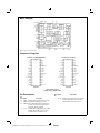
Block Diagram
DS009151-1
Note: Pin names show Microwire mode.
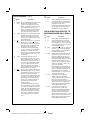
Connection Diagrams
Pin Names for MICROWIRE Mode
Pin Names for GCI Mode
DS009151-2
DS009151-3
Top View
Top View
Order Number TP3410J
See NS Package Number J28A
Pin Descriptions
Pin
Symbol
No.
Pin
Symbol
No.
Description
24
9
23
GNDA Negative power supply pins, which must
GNDD1 be connected together close to the
GNDD2 device. All digital signals are referenced
to these pins, which are normally at the
system 0V (Ground) potential.
5
VCCA
8
VCCD
Description
Positive power supply input for the digital
section, which must be +5V ± 5% and
must be directly connected to VCCA.
Positive power supply input for the analog
sections, which must be +5V ± 5% and
must be directly connected to VCCD.
www.national.com
PrintDate=1997/07/09 PrintTime=13:37:52 1109 ds009151 Rev. No. 1
2
Proof
2
Pin Descriptions
Pin
Symbol
No.
21
20
10
22
25
(Continued)
Pin
Symbol
No.
1
4
Description
MCLK/ The 15.36 MHz Master Clock input, which
XTAL
requires either a parallel resonance
crystal to be tied between this pin and
XTAL2, or a CMOS logic level clock input
from a stable source (a TTL Logic “1”
level is not suitable). This clock does not
need to be synchronized to the system
clock (BCLK and FS), see Section 5.1.
TSFS
LSD
/RSFS
Transmit 2B1Q signal differential outputs
to the line transformer. When used with
an appropriate 1:1.5 step-up transformer
and the line coupling circuit
recommended in the Applications section,
the line signal conforms to the output
specifications in the ANSI standard.
PIN DESCRIPTIONS SPECIFIC TO
MICROWIRE MODE ONLY (MW = 1)
XTAL2 The output of the crystal oscillator, which
should be connected to one end of the
crystal, if used; otherwise this pin must
be left open-circuit. Not recommended to
drive additional logic.
TS r/
SCLK
Lo+
Lo−
Description
Pin
Symbol
No.
This pin has 2 functions: in LT mode it is
an open-drain n-channel TS r output,
which goes low only during the time-slots
assigned to the B1 and B2 channels at
the Br pin in order to enable the
TRI-STATE ® control of the backplane
line-driver. In NT mode it is a full CMOS
15.36 MHz synchronous clock output
which is frequency-locked to the received
line signal (unlike the XTAL pins it is not
free-running).
Description
2
3
Li+
Li−
Receive 2B1Q signal differential inputs
from the line transformer. For normal
full-duplex operation, these pins should
be connected to the Lo ± pins through the
recommended coupling circuit, as shown
in the Applications section.
28
MW
The Microwire/GCI Select pin, which must
be tied to VCCD to enable the Microwire
Interface with any of the data formats at
the Digital System Interface.
12
BCLK
The Bit Clock pin, which determines the
data shift rate for “B” and “D” channel
data on the digital interface side of the
device. When Digital System Interface
(DSI) Slave mode is selected (see Digital
Interfaces section), BCLK is an input
which may be any multiple of 8 kHz from
256 kHz to 4.096 MHz. It need not be
synchronous with MCLK.
The Transmit Superframe Sync pin,
which indicates the start of each 12 ms
transmit superframe at the U Interface. In
NT mode this pin is always an output. In
LT mode it may be selected to be either
an input or CMOS output via Register
CR2; when selected as an output the
signal is a square-wave. Must be tied low
if selected as input yet not driven.
When DSI Master mode is selected, this
pin is a CMOS output clock at 256 kHz,
512 kHz, 1.536 MHz, 2.048 MHz or 2.56
MHz, depending on the selection in
Command Register 1. It is synchronous
with the data on Bx and Br.
This pin is an open-drain n-channel Line
Signal Detector output, which is normally
high-impedance and pulls low only when
the device is powered down and an
incoming wake-up signal is detected from
the far-end. As an option this pin can be
programmed to be an output indicating
the start of the received superframe at
the U interface; an external pull-up
resistor is required.
The RSFS signal indicates the start of
each 12 ms receive superframe from the
U Interface and is available in NT and LT
modes. The Received Superframe Synch
clock output is accessible on pin 25 by
writing X’1C04 and X’100C (or X’100E)
during device initialization. See TP3410
users manual AN-913, Part II Section
4.18).
6
FSa
In DSI Slave mode, this pin is the
Transmit Frame Sync pulse input,
requiring a positive edge to indicate the
start of the active channel time for
transmit B1 channel data into Bx. In DSI
Master mode, this pin is a Frame Sync
CMOS output pulse conforming with the
selected Digital Interface format.
7
FSb
In DSI Slave mode, this pin is the
Receive Frame Sync pulse input,
requiring a positive edge to indicate the
start of the active channel time of the
device for receive B channel data out
from Br (see DSI Format section). In DSI
Master mode this pin is a Frame Sync
CMOS output pulse conforming with the
selected Digital Interface format.
3
PrintDate=1997/07/09 PrintTime=13:37:53 1109 ds009151 Rev. No. 1
www.national.com
Proof
3
Pin Descriptions
(Continued)
Pin
Symbol
No.
PIN DESCRIPTIONS SPECIFIC TO
MICROWIRE MODE ONLY
(MW = 1) (Continued)
Pin
Symbol
No.
Bx
The digital input for B and, if selected, D
channel data to be transmitted to the line;
must be synchronous with BCLK.
11
Br
The TRI-STATE output for B and, if
selected, D channel data received from
the line; it is synchronous with BCLK.
18
CI
The Microwire control channel data input.
19
CO
The Microwire control channel
TRI-STATE output for status information.
When not enabled by CS , this output is
high-impedance.
17
CCLK
The Microwire control channel Clock
input, which may be asynchronous with
BCLK.
27
CS
The Chip Select input, which enables the
Control channel data to be shifted in and
out when pulled low. When high, this pin
inhibits the Control interface.
26
16
15
14
INT
Dx
Dr
DCLK
27
MO
The GCI Master/Slave select input for the
clock direction. Connect this pin low to
select BCLK and FSa as inputs i.e., GCI
Slave; Selection of LT or NT mode must
be made in register CR2. When MO is
connected high, NT Mode is automatically
selected, and BCLK, FSa and FSb are
outputs, i.e., the GCI Master, see Section
8.
12
BCLK
The Bit Clock pin, which controls the
shifting of data on the Bx and Br pins, at
a rate of 2 BCLK cycles per data bit.
When GCI Slave mode is selected (see
Digital Interfaces section), BCLK is an
input which may be any multiple of
16 kHz from 512 kHz to 6.144 MHz. It
need not be synchronous with MCLK.
Description
13
When GCI Master mode is selected, this
pin is a CMOS output clock at 512 kHz or
1.536 MHz, depending on the connection
of the S2/CLS pin. It is synchronous with
the data on Bx and Br.
The Interrupt output, a latched open-drain
output signal which is normally
high-impedance, and goes low to indicate
a change of status of the loop
transmission system. This latch is cleared
when the Status Register is read by the
microprocessor.
When the D-port is enabled this pin is the
digital input for D channel data to be
transmitted to the line clocked by DCLK
or BCLK, see Register CR2. When the
D-port is disabled via CR2, this pin must
be tied to GND.
When the D-port is enabled this pin is the
TRI-STATE output for D channel data to
be received from the line clocked by
DCLK or BCLK, see Register CR2.
13
Bx
The digital input for multiplexed B, D and
control data clocked by BCLK at the rate
of 1 data bit per 2 BCLK cycles, and 32
data bits per 8 kHz frame defined by
FSa.
11
Br
The open-drain n-channel output for
multiplexed B, D and control data clocked
by BCLK at the rate of 1 data bit per 2
BCLK cycles, and 32 data bits per 8 kHz
frame defined by FSa. A pull-up resistor
is required to define the logical 1 state.
6
FSa
17
19
7
When the D-port is enabled, in DSI Slave
or Master mode, this is a 16 kHz clock
CMOS output for D channel data. When
the D-port is disabled or not used, this
pin must be left open-circuit.
In GCI Slave mode (MO connected low),
this pin is the 8 kHz Frame Sync pulse
input, requiring a positive edge to indicate
the start of the GCI slot time for both
transmit and receive data at Bx and Br. In
GCI Master mode, this pin is the 8 kHz
Frame Sync CMOS output pulse.
S2/CLS In GCI Slave mode (MO = 0):
S1
input pins S2, S1 and S0 together
SO/FSb provide a 3-bit binary-coded select port
for the GCI channel number; S2 is the
msb. These pins must be connected
either to VCCD or GND to select the
1-of-8 GCI slots which are available if
BCLK ≥ 4.096 MHz is used.
In GCI Master mode (MO = 1)
PIN DESCRIPTIONS SPECIFIC TO
GCI MODE ONLY (MW = 0)
Pin
Symbol
No.
28
MW
S2/CLS is the GCI Clock Select input.
Connect this pin high to select BCLK =
1.536 MHz; connect CLS low to select
BCLK = 512 kHz. SO/FSb is a Frame
Sync CMOS output pulse which identifies
the B2 channel.
Description
The Microwire/GCI select input, which
must be tied to GND to enable the GCI
mode at the Digital System Interface.
www.national.com
PrintDate=1997/07/09 PrintTime=13:37:55 1109 ds009151 Rev. No. 1
Description
4
Proof
4
Pin Descriptions
grammed register data is retained. Also, if the loop had been
successfully activated and deactivated, the adaptive circuits
are “frozen” and the coefficients in the Digital Signal Processors are stored to enable rapid reactivation (“warm-start”).
(Continued)
PIN DESCRIPTIONS SPECIFIC TO
GCI MODE ONLY (MW = 0) (Continued)
Pin
Symbol
No.
18
16
15
ES1
ES2
LEC
1.3 Reset
Description
A software reset command is provided to enable the clearing
of the Activation sequencer without disconnecting the power
supply to the device, see the Activation section.
While in GCI mode, the ES1, ES2 pins
are local input pins. The status of the
pins can be accessed via the RXM56
register bits 5,6 corresponding to ES1,
ES2.
2.0 TRANSMISSION SECTION
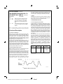
2.1 Line Coding And Frame Format
For both directions of transmission, 2B1Q coding is used, as
illustrated in Figure 1. This coding rule requires that binary
data bits are grouped in pairs, and each pair is transmitted
as a symbol, the magnitude of which may be 1 out of 4
equally spaced voltage levels (a “Quat”). There is no symbol
value at 0V in this code, the relative quat magnitudes being
± 1 (the “inner” levels) and ± 3 (the “outer” levels). No redundacy is included in this code, and in the limit there is no
bound to the RDS, although scrambling controls the RDS in
a practical sense ( RDS is the Running Digital Sum, which is
the algebraic summation of all symbol values in a transmission session).
The frame format used in the TP3410 follows the ANSI standard, shown in Tables 1, 2. Each complete frame consists of
120 quats, with a line bit rate of 80 kq/s, giving a frame duration of 1.5 ms. A 9 quat syncword defines the framing
boundary. Furthermore, a “superframe” consisting of 8
frames is defined in order to provide sub-channels within the
spare bits M1 to M6. Inversion of the syncword defines the
superframe boundary. Prior to transmission, all data, with the
exception of the syncword, is scrambled using a
self-synchronizing scrambler to implement the specified
23rd-order polynomial. Descrambling is included in the receiver.
Latched External Control output, which is
the output of a latched bit in the TXM56
Register.
Note 1: *Crystal specifications: 15.36 MHz ± 50 ppm parallel resonant;
RS ≤ 20Ω. Load with 33 pF to GND each side (+7 pF due to pin capacitance).
Functional Description
1.1 Power-On Initialization
When power is first applied, power-on reset circuitry initializes the TP3410 and puts it into the power-down state, in
which all the internal circuits including the Master oscillator
are inactive and in a low power state except for the
Line-Signal Detect circuit; the line outputs Lo+/Lo− are in a
high impedance state. All programmable registers and the
Activation Sequence Controller are reset.
All states in the Command Registers initialize as shown in
their respective code tables. The desired modes for all programmable functions may be selected by writing to these
registers via the control channel (Microwire or Monitor channel, as appropriate). Microwire is functional regardless of
whether the device is powered up or down, whereas the GCI
channel requires the BCLK to be running.
1.2 Power-Up/Power-Down Control
Before powering up the device, the Configuration Registers
should be programmed with the required modes.
In Microwire mode and GCI Slave mode, the device is powered up and the MCLK started by writing the PUP command,
as described in the Activation section. In GCI Master mode,
there are 2 methods of powering up the device: the Bx data
input can be pulled low (local power-up command) or the
10 kHz wake-up tone may be received from the far-end.
First Bit
Second Bit
(Sign)
(Magnitude)
Quat
Pulse Amplitude
1
0
+3
+2.5V
1
1
+1
+0.83V
0
1
−1
−0.83V
0
0
−3
−2.5V
(Note 2)
Note 2: For isolated pulses into a 135Ω termination with recommended
transformer interface.
The power-down state may be re-entered by writing a
Power-down command. In the power-down state, all pro-
DS009151-25
FIGURE 1. 2B1Q Line-Coding Rule
5
PrintDate=1997/07/09 PrintTime=13:37:59 1109 ds009151 Rev. No. 1
www.national.com
Proof
5
Functional Description
(Continued)
TABLE 1. 2B1Q Superframe Format and Overhead Bit Assignments
(a) Network → NT
Framing
12x(2B+D)
Quat Positions
1–9
10–117
118s
118m
119s
119m
120s
120m
Bit Positions
1–18
19–234
235
236
237
238
239
240
Superframe#
Basic Frame#
Sync Word
2B+D
M1
M2
M3
M4
M5
M6
1
1
ISW
2B+D
eoca1
eoca2
eoca3
act
1
1
2
SW
2B+D
eocdm
eoci1
eoci2
dea
1
febe
3
SW
2B+D
eoci3
eoci4
eoci5
1
crc1
crc2
4
SW
2B+D
eoci6
eoci7
eoci8
1
crc3
crc4
5
SW
2B+D
eoca1
eoca2
eoca3
1
crc5
crc6
6
SW
2B+D
eocdm
eoci1
eoci2
1
crc7
crc8
7
SW
2B+D
eoci3
eoci4
eoci5
uoa
crc9
crc10
8
SW
2B+D
eoci6
eoci7
eoci8
aib
crc11
crc12
1
ISW
2, 3, …
Overhead Bits (M1–M6)
TABLE 2. 2B1Q Superframe Format and Overhead Bit Assignments
(b) NT → Network
Framing
12x(2B+D)
Quat Positions
1–9
10–117
118s
118m
119s
119m
120s
120m
Bit Positions
1–18
19–234
235
236
237
238
239
240
Superframe#
Basic Frame#
Sync Word
2B+D
M1
M2
M3
M4
M5
M6
1
1
ISW
2B+D
eoca1
eoca2
eoca3
act
1
1
2
SW
2B+D
eocdm
eoci1
eoci2
ps1
1
febe
3
SW
2B+D
eoci3
eoci4
eoci5
ps2
crc1
crc2
4
SW
2B+D
eoci6
eoci7
eoci8
ntm
crc3
crc4
5
SW
2B+D
eoca1
eoca2
eoca3
cso
crc5
crc6
6
SW
2B+D
eocdm
eoci1
eoci2
1
crc7
crc8
7
SW
2B+D
eoci3
eoci4
eoci5
1
crc9
crc10
8
SW
2B+D
eoci6
eoci7
eoci8
1
crc11
crc12
1
ISW
2, 3, …
Overhead Bits (M1–M6)
Note 3: 8 x 1.5 ms Basic Frames = 12 ms/Superframe. NT-to-Network superframe is offset from Network-to-NT superframe by 60 ± 2 quats (about 0.75 ms). All bits
other than the Sync Word are scrambled.
Symbols & Abbreviations
act
=
aib
=
crc
=
cso
=
dea
=
eoc
=
start-up bit ( = 1 during start-up)
alarm indication bit ( = 0 to indicate
interruption)
febe
=
ntm
=
ps1, ps2 =
cyclic redundacy check: covers 2B+D + M4
1 = most significant bit
2 = next significant bit etc.
far end block error bit ( = 0 for errored
superframe)
NT in test mode bit ( = 0 to indicate test
mode)
power status bits ( = 0 to indicate power
problems)
Quat
=
cold-start-only bit ( = 1 to indicate
cold-start-only)
turn off bit ( = 0 to announce turn off)
pair of bits forming quaternary symbol
s = sign bit (first in quat)
m = magnitude bit (second in quat)
sai
=
embedded operations channel
a = address bits
uoa
=
S-activation-indication bit ( = 1 for S/T
activity)
U-only-activation bit ( = 1 to activate S/T)
dm =
“1”
=
“1*”
=
reserved bit for future standard ( = 1)
network indicator bit ( = 1, reserved for
network use)
2B+D
=
user data, bits 19–234 in frame
i
=
data/message indicator (0 = data,
1 = message)
information (data or message)
www.national.com
PrintDate=1997/07/09 PrintTime=13:38:03 1109 ds009151 Rev. No. 1
6
Proof
6
Functional Description
M
=
SW/ISW =
the frame and superframe syncwords. Frame lock will be
maintained until errored sync words are detected for 480 ms.
If a loss-of-sync condition persists for 480 ms the device will
cease transmitting and go into a RESET state.
While the receiver is synchronized, data is descrambled using the specified polynomial, and the individual channels demultiplexed and passed to their respective processing circuits.
(Continued)
M-channel, bits 235–240 in frame
synchronization word/inverted
synchronization word, bits 1–18 in frame
2.2 Line Transmit Section
Data to be transmitted to the line consists of the customer’s
2B+D channel data and the data from the maintenance processor, plus other “spare” bits in the overhead channels.
This data is multiplexed and scrambled prior to addition of
the syncword. A pulse waveform synthesizer then drives the
transmit filter, which in turn passes the line signal to the line
driver. The differential line-driver outputs, Lo+ and Lo−, are
designed to drive a transformer through an external termination circuit. A 1:1.5 transformer, designed as shown in the
Applications section, results in a signal amplitude of nominally 2.5V pk on the line for single quats of the outer ( ± 3) levels. Note, however, that because of the RDS accumulation of
the 2B1Q line code, continuous random data will produce
signal swings considerably greater than this on the line.
Short-circuit protection is included in the output stage; overvoltage protection must be provided externally.
Whenever the loop is deactivated, either powered up or powered down, a Line Signal Detect circuit is enabled to detect
the presence of an incoming 10 kHz wake-up tone if the
far-end starts to activate the loop. The LSD circuit generates
an interrupt and, if the device is powered down, pulls the
LSD pin low; either of these indicators may be used to alert
an external controller, which must respond with the appropriate commands to initiate the activation sequence (see the
Activation section).
3.0 ACTIVATION CONTROL: OVERVIEW
The TP3410 contains an automatic sequencer for the complete control of the start-up activation sequence specified in
the ANSI standard. Both the “cold-start” and the fast
“warm-start” are supported. Interaction with an external controller requires only Activate Request and Deactivate Request commands, with the option of inserting breakpoints in
the sequence for additional external control if desired. Automatic control of the “act” and “dea” bits in the M4 bit positions
is provided, along with the specified 40 ms and 480 ms timers used during deactivation. A 15 second default timer is
also included, to prevent system lock-up in the event of a
failed activation attempt. Section 11 gives an overview of the
activation handshake between the TP3410 and the controller. See TP3410 User’s Manual AN-913 for additional information.
2.3 Line Receive Section
The receive input signal should be derived from the transformer by means of a coupling circuit as shown in the Applications section. At the front-end of the receive section is a
continuous filter followed by a switched-capacitor low-pass
filter, which limits the noise bandwidth. A Hybrid Balance Filter provides a degree of analog echo-cancellation in order to
limit the dynamic range of the composite signal. An A/D converter then samples the composite received signal prior to
the cancellation of the “echo” from the local transmitter by
means of an adaptive digital transversal filter (i.e., the
“echo-canceller”). Following this, the attenuation and distortion (inter-symbol interference) of the received signal from
the far-end, caused by the transmission line, are equalized
by a second adaptive digital filter configured as a Decision
Feedback Equalizer (DFE), thereby restoring a “flat” channel
response with maximum received eye opening over a wide
spread of cable attenuation characteristics.
From the received line signal, a Timing Recovery circuit
based on a DPLL (Digital Phase-Locked Loop) recovers a
low-jitter clock for optimum sampling of the received symbols. The MCLK input provides the reference clock for the
DPLL at 15.36 MHz. Received data is then detected, with automatic correction for line signal polarity if necessary, and a
flywheel synchronization circuit searches for and locks onto
4.0 MAINTENANCE FUNCTIONS: OVERVIEW
4.1 M Channel Processing
In each frame of the superframe there are 6 “Overhead” bits
assigned to various control and maintenance functions of the
DSL. Some processing of these bits may be programmed via
the Command Registers, while interaction with an external
controller provides the flexibility to take full advantage of the
maintenance channels. New data written to any of the overhead bit Transmit Registers is resynchronized internally to
the next available complete superframe or half-superframe,
as appropriate. In addition, the SFS pin may be used to indicate the start of each superframe in 1 direction, see Figure 2
and Register CR2.
7
PrintDate=1997/07/09 PrintTime=13:38:06 1109 ds009151 Rev. No. 1
www.national.com
Proof
7
Functional Description
(Continued)
DS009151-26
FIGURE 2. Superframe Sync Pin Timing
4.2 Embedded Operations Channel
The EOC channel consists of 2 complete 12-bit messages
per superframe, distributed through the M1, M2 and M3 bits
of each half-superframe as shown in Tables 1, 2. Each message is composed of 3 fields; a 3-bit address identifying the
message destination, a 1-bit indicator for the data mode, i.e.,
encoded message or raw data, and an 8-bit information byte.
The Microwire port or GCI Monitor Channel provides access
to the complete 12 bits of every message in the TX EOC and
the RXEOC Registers. If one of the defined encoded messages is received, e.g., Send Corrupted CRC, then the appropriate Command Register instruction must be written to
the device to invoke the function.
in the next superframe. If there are no errors in a superframe, febe is set = 1, and if there is one or more errors febe
is set = 0.
The TP3410 also includes a readable 8-bit Block Error
Counter BEC1, which is decremented by 1 each superframe
in which febe = 0 or nebe = 0 is received. Section 10.5 describes the operation of this counter.
On first application of power, and after the software reset
(X’1880, X’1800), both the ECT1 as well as BEC1 are initialized to X’FF. See the Block Error Counter section for more
details.
4.3 M4 Bits
The M4 bit position of every frame is a transparent channel
in which are transmitted data bits loaded from the M4 Transmit Register TXM4, one byte per superframe. On the receive
side the M4 bits from one complete superframe are sent to a
checking circuit which holds each new M4 byte and compares it against the previous M4 byte(s) for validation prior to
sending it to the RXM4 Receive Register; Register OPR provides several options for control of this validation.
5.1 Clocking
In LT applications (network end of the Loop), the Digital System Interface (DSI) normally accepts BCLK and FS signals
from the network, requiring the selection of DSI or GCI Slave
mode in Register CR1. A Digital Phase-Locked Loop (DPLL
#2) on the TP3410 allows the MCLK frequency to be plesiochronous (i.e. free-running) with respect to the network
clocks, (BCLK and the 8 kHz FSa input). With a tolerance on
the MCLK oscillator of 15.36 MHz ± 100 ppm, the lock-in
range of DPLL2 allows the network clock frequency to deviate up to ± 50 ppm from nominal.
In NT applications, when the device is in NT mode and is
slaved to loop timing recovered from the received line signal,
DSI or GCI Master mode should normally be selected. In this
case BCLK, FS and SCLK (15.36 MHz) signals are outputs
which are phase-locked to the recovered clock. A
slave-slave mode is also provided, however, in which the
Digital Interface data buffers on the TP3410 allow BCLK and
FSa/b to be input from an external source, which must be
frequency-locked (but may take an arbitrary phase) to the received line signal; in this case DSI or GCI Slave mode
should be selected.
5.0 DIGITAL INTERFACE: ALL FORMATS
4.4 Spare M5 And M6 Bits
Overhead bits M5 and M6 in frame 1 (M51 and M61) and M5
in frame 2 (M52) are transparently transmitted from the
Transmit M56 Spare Bit Register to the line. In the receive direction, data from these bit positions is sent to a checking circuit which holds the new M5/M6 spare bits and compares
them against the previous M5/M6 bits for validation prior to
sending them to the Receive M56 Spare Bit Register; the
OPR Register provides several options for control of this
validation.
4.5 CRC Circuit
In the transmit direction an on-chip crc calculation circuit automatically generates a checksum of the 2B+D+M4 bits using the polynomial x12+x11+x3+x2+x+1. Once per superframe the crc is transmitted in the specified M5 and M6 bit
positions (see Tables 1, 2). In the receive direction a checksum is again calculated on the same bits as they are received and, at the end of the superframe, compared against
the crc transmitted with the data. The result of this comparison generates a “Far End Block Error” bit (the febe bit),
which is transmitted back towards the other end of the DSL
www.national.com
PrintDate=1997/07/09 PrintTime=13:38:08 1109 ds009151 Rev. No. 1
5.2 Data Buffers
The TP3410 buffers the 2B+D data at the Digital Interface in
elastic FIFOs, which are 3 frames deep in each direction.
When the Digital Interface is a timing slave these FIFOs
compensate for relative jitter and wander between the Digital
Interface clocks (BCLK and FSa/b) and bit and frame timing
at the Line Interface. Each buffer can absorb wander up to
8
Proof
8
Functional Description
(Continued)
18 µs in ≥ 10 secs without “slip”, exceeding CCITT recommendation Q.502. Excessive wander causes a controlled
slip of one complete frame.
6.0 DIGITAL INTERFACE DATA FORMATS IN
MICROWIRE MODE (MW = 1)
When the MW pin is tied high to enable the Microwire Port
for control and status, the Digital System Interface on the
TP3410 provides a choice of four multiplexed formats for the
B and D channel data, as shown in Figures 3, 4, 5, 6, 7.
These apply in both LT and NT modes of the device, and selection is made via Register CR1. Selection of DSI Master or
Slave mode must also be made in CR1. Within each format
there is also an independent selection available to either
multiplex the D channel (Tx and Rx) data on the same pins
as the B channels, or via the separate D-channel access
pins, DCLK, Dx and Dr, see Section 6.3.
Format 1:
Format 2:
In Format 1, the 2B+D data transfer is assigned
to the first 18 bits of the frame on the Bx and Br
pins. Channels are assigned as follows: B1 (8
bits), B2 (8 bits), D (2 bits), with the remaining
bits ignored until the next frame sync pulse.
When the D channel port is enabled (see CR2),
only the 2 B channels use the Bx and Br pins;
the D bits are assigned to the 17th and 18th bits
of the frame on the Dx and Dr pins. Figure 3
shows this format in DSI Slave Mode, and Figure 6 shows DSI Master Mode.
Format 2 is the IDL, in which the 2B+D data
Format 3:
transfer is assigned to the first 19 bits of the
frame on the Bx and Br pins. Channels are assigned as follows: B1 (8 bits), D (1 bit), 1 bit ignored, B2 (8 bits), D (1 bit), with the remaining
bits ignored until the next frame sync pulse. Figure 4 shows this format in DSI Slave Mode, and
Figure 7 shows DSI Master Mode.
This format provides time-slot assignment capability for the B1 and B2 channels, which can be
independently assigned to any 8-bit wide
time-slot from 64 (or less) on the Bx and Br pins;
the Transmit and Receive directions are also independently assignable. Also the D channel can
be assigned to any 2-bit wide time-slot from 256
(or less) on the Bx and Br pins (D port disabled)
or on the Dx and Dr pins (see D-Channel Port
section). Figure 5
Functional Description
(Continued)
DS009151-6
Delayed timing mode must be selected;
Time-slot immediate mode only (no TSA).
FIGURE 4. DSI Format 2 (IDL): Slave Mode
DS009151-7
Transmit slots are numbered relative to FSa, and receive slots relative to FSb.
Shown with examples of offset frames and Time-slot Assignments.
FIGURE 5. DSI Format 3 (Time-Slot Assignment) : Slave Mode
DS009151-8
FSa defines B1 channel for Tx and Rx.
FSb defines B2 channel for Tx and Rx.
FIGURE 6. DSI Format 1: Master Mode
www.national.com
PrintDate=1997/07/09 PrintTime=13:38:10 1109 ds009151 Rev. No. 1
10
Proof
10
Functional Description
(Continued)
DS009151-9
FIGURE 7. DSI Format 2 (IDL): Master Mode
DS009151-10
Transmit and Receive slots are numbered relative to FSa.
FIGURE 8. DSI Format 3: Master Mode
lected. Again, either a delayed or non-delayed relationship
between FSa, FSb and the start of the first time-slot can be
selected.
6.1 FS Relationship To Data (Microwire Mode)
For applications on a line-card, in DSI Slave Mode, the B and
D channel slots can be interfaced to a Time-Division Multiplexed (TDM) bus and assigned to a time-slot. The repetition
rate of the FS input signals must be 8 kHz and must be synchronized to the BCLK input, which may be any frequency
from 256 kHz to 4.096 MHz in 8 kHz increments. Two different relationships may be established between the FS inputs
and the actual time-slots on the PCM busses by setting the
DDM bit in Control Register CR1, see Figures 3, 4, 5, 6, 7,
Figure 18 and Figure 19. Non-delayed data mode is similar
to long frame timing on the TP3050/60 series of devices
(COMBO I): the time-slots are defined by the 8-bit duration
FSa and FSb signals. The alternative is to use Delayed Data
Mode, which is similar to short frame sync timing on COMBO
I, in which each FS input indicates the start of the first
time-slot.
6.2 B Channel Time-slot Assignment; Format 3 Only
(Microwire Mode)
In Format 3 only, the TP3410 provides programmable
time-slot assignment for selecting the Transmit and Receive
B channel time-slots. Following power-on, the device is automatically in Non-delayed Data Mode; if Delayed Data Mode
is required it must first be selected (see CR1) prior to using
Time-slot Assignment, and the FS pulses must conform to
the Delayed Data timing format. The actual transmit and receive time-slots are then determined by the internal
Time-slot Assignment counters, programmed via Control
Registers TXB1, TXB2, RXB1 and RXB2. Normally used in
DSI Slave mode, Format 3 allows a frame to consist of up to
64 time-slots of 8 bits each with BCLK up to 4.096 MHz.
A new assignment becomes active on the second frame following the end of the 16-bit Chip Select.
Serial B channel data is shifted into the Bx input during each
assigned Transmit time-slot on the falling edges of BCLK.
During each assigned Receive time-slot, the Br output shifts
data out on the rising edges of BCLK. Also, with the device in
LT Mode, the TS r pin is an open drain n-channel pull-down
output which goes low during the selected time-slots for the
received B1 and B2 channels at the Br pin to control the
TRI-STATE Enable of a backplane line-driver; it is
high-impedance at all other times.
In NT Mode, when DSI Master mode is selected, FSa and
FSb are outputs indicating the B1 (or TS0) and the B2 (or
TS1) channels respectively. BCLK is also an output at the
serial data shift rate, which is dependent on the format se-
6.3 D Channel Port Selection (Microwire Mode)
In any of the DSI Formats, the 2 D channel bits per frame
may either be multiplexed with the B channels on the Bx and
Br pins, or may be accessed via the separate D channel port
consisting of Dx and Dr. Furthermore, when using the separate D port the data shift clock may either be a continuous,
unframed data stream using the 16 kHz clock output at
DCLK, see Figure 9, or may use the BCLK, see Figures 10,
11, 12. Selection of these options is via Control Register
CR2.
11
PrintDate=1997/07/09 PrintTime=13:38:12 1109 ds009151 Rev. No. 1
www.national.com
Proof
11
Functional Description
(Continued)
Function
Format Number
1
2
3
4
Yes
Yes
Yes
Yes
6.4 D Channel Time-Slot Assignment
Tx and Rx Frames
with
In addition to B channel TSA, Format 3 allows independent
Time Slot Assignment for the Transmit and Receive D channels, which may be programmed via Registers TXD and
RXD. As with the B channels, up to 64 time-slots are available if BCLK = 4.096 MHz, and in addition the 2 D bits may
be assigned, in pairs, to specific bit locations within the
time-slot; that is in bits 1 and 2; 3 and 4; 5 and 6; or 7 and 8.
D channel TSA may be used either with the D channel multiplexed with the B channel data, or with the separate D
Channel port clocked with BCLK; it cannot be used with the
16 kHz clock option at DCLK.
Any Phase?
FSa
FSb
No
No
Yes
No
D Port Available?
Yes
Yes
Yes
Yes
Summary of DSI Master Mode
Options
Function
Summary of DSI Slave Mode
Options
Function
TSA Available?
FSa
FSb
FS Formats
Format Number
Format Number
1
2
3
4
B1
B1
TS0
B1
B2
B2
TS1
B2
Non-
Delayed
Non-
Non-
Only
1
2
3
4
Delayed
Tx
B1
Tx
B1
Tx
TS0
Tx
B1
and
and
Delayed
Delayed
Rx
B1
Rx
B1
Rx
TS0
Rx
B1
Non-Delayed Timing?
Yes
No
Yes
Yes
Delayed Timing?
Yes
Yes
Yes
No
Delayed Delayed
Only
TSA Available?
No
No
Yes
No
D Port Available?
Yes
Yes
Yes
Yes
Note: All Formats: Tx and Rx frames always aligned.
DS009151-11
FIGURE 9. D-Port Interface Timing Using DCLK in 16 kHz Mode
DS009151-12
FIGURE 10. D-Port Interface Timing Using BCLK Format 1
www.national.com
PrintDate=1997/07/09 PrintTime=13:38:14 1109 ds009151 Rev. No. 1
12
Proof
12
Functional Description
(Continued)
DS009151-13
FIGURE 11. D-Port Interface Timing Using BCLK Format 2
DS009151-14
Shown with example of Time-slot Assignment, and FSa = FSb
FIGURE 12. D-Port Interface Timing Using BCLK Format 3
7.0 MICROWIRE CONTROL PORT (MW = 1)
When Format 1, 2, 3 or 4 is used, control information and
maintenance channel data is written into and read back from
the TP3410 via the Microwire port consisting of the control
clock CCLK; the serial data input, CI, and output, CO; the
Chip Select input, CS and the interrupt output INT . The MW
pin must be tied high to enable this port, and the port may be
used regardless of whether the device is powered up or
down. Figure 13 and Figures 21, 22, 23 show the timing,
which is compatible with the Microwire port on the HPC and
COPs families of microcontrollers, and Table 3 and Table 4
list the control functions and status indicators.
All read and write operations require 2 contiguous bytes. As
shown in Table 3 and Table 4, the first byte is the register address and the second byte is the data byte. Status Registers
request service under control of the Interrupt Stack, with the
priority order listed in Table 4.
To shift data to and from the TP3410, CCLK must be pulsed
high 16 times while CS is low. Data on the CI input is shifted
into the serial input register on the rising edge of each CCLK
pulse; simultaneously, data is shifted out from CO on each
falling edge of CCLK. Bit 7 of byte 1 is shifted first. CS must
return high at the end of the 2nd byte, after which the contents of the input shift register are decoded, and the data is
loaded into the appropriate programmable register. Pulling
CS low also clears the INT pin if it was pulled low; if another
interrupt condition is queued on the Interrupt Stack it can
only pull the INT pin low when CS is high. When CS is high
the CO pin is in the high-impedance state, enabling the CO
pins of many devices to be multiplexed together.
TP3410 supports two popular formats used in typical terminal equipment applications.
1. CCLK idling LOW when CS pin is inactive HIGH, pulsing
LOW/HIGH/LOW for 16 clocks, then returning back to
LOW for idle condition. Data is output on CO pin on the
negative edge and data sampled in on the positive edge
of CCLK. This format (shown in Figure 22) is normally
used with NSC’s microcontrollers from the HPC or the
COP8 family.
2. CCLK idling HIGH when CS pin inactive HIGH, pulsing
HIGH/LOW/HIGH for 17 clocks, then returning back to
HIGH for idle condition. Data is output on CO pin on the
negative edge and data sampled in on the positive edge
of CCLK. This format (shown in Figure 23) is normally
used with other alternate microcontrollers in the industry.
The first 16 clock pulses are the normal low-going
pulses to shift and sample the microwire data. The 17th
pulse is generated with software by toggling the
CCLK clock polarity bit on the SCP port of MC6302 or
MC145488. It is necessary to deactivate the CS pin
(bring it high) while the CCLK is low as shown in Figure
23.
8.0 GCI MODE (MW = 0)
Selected by tying the MW pin low, the GCI interface is designed for systems in which PCM and control data are multiplexed together into 4 contiguous bytes per 8 kHz frame.
Furthermore, in Subscriber Line Cards and NT1–2’s (where
the Digital Interface is slaved to external timing) up to 8 GCI
channels may be carried in 1 frame of a GCI multiplex, with
a combined bit rate from 256 kb/s up to 3088 kb/s.
Pin-programmable GCI-channel assignment for 8 GCI channels is provided.
The TP3410 has an enhanced MICROWIRE port such that it
can connect to standard MICROWIRE master devices (such
an NSC’s HPC and COP families) as well as the SCP (serial
control port) interface master from the Motorola
micro-controller family. SCP is supported on devices such as
MC68302 or the MC145488 HDLC.
Note that GCI mode on the TP3410 requires messages in
the Embedded Operations Channel to be processed by a local microcontroller. In Line card and TE applications, GCI
mode can be used with a device such as the TP3451 HDLC
13
PrintDate=1997/07/09 PrintTime=13:38:16 1109 ds009151 Rev. No. 1
www.national.com
Proof
13
Functional Description
are synchronized to the data received from the line, and GCI
channel 0 is always used. As a GCI Slave, BCLK and FSa
must be sourced externally, typically from a system backplane, and pins S0–S2 must be connected high or low to select the required GCI channel. To use the single channel
mode, a 512 kHz BCLK is required, and S2, S1 and S0 must
be connected to GND (GCI Channel 0). To use the multiplex
mode with a GCI Slave device, the 4 pins are commoned between up to 8 devices, forming a “wire-AND” connection with
the Br pins. The BCLK frequency must be at least n x 512
kHz, where n is the number of devices. In fact BCLK may be
operated up to 6144 kHz if required, to leave up to 4 additional GCI channels unoccupied by TP3410’s (and available
for other uses). Clock and channel selection are shown in
the following table:
(Continued)
controller to provide the interface for the microcontroller to
access the EOC Registers. To use the device in an NT-1 or
Regenerator, a microcontroller is required and Microwire
mode should be used on the TP3410.
8.1 GCI Physical Interface
The interface physically consists of four wires:
— Transmit data to line:
Bx
— Receive data from line: Br
— Bit clock at 2 cycles/bit: BCLK
— 8 kHz frame sync:
FSa
Data is synchronized by the BCLK and FSa clock inputs.
FSa insures re-initialization of the time-slot counter at the beginning of each 8 kHz frame, with the rising edge of FSa being the reference time for the first GCI channel bit. Data is
clocked in both directions at half the BCLK input frequency.
Data bits are output from the device on a rising edge of
BCLK and sampled on the second falling edge of BCLK; unused slots are high impedance. Br is an open-drain
n-channel output, with internal detection for contention resolution on the Monitor and C/I channels between devices attempting to use the same GCI channel (typically in a TE application).
A device may be either the Master or Slave of the GCI timing.
As a Master it is the source of BCLK, FSa and FSb, which
Pin Name
LT and NT1–2
MW
0
NT1 and TE
0
MO
0 (GCI Slave)
S2/CLS
S2 (msb)
1 (GCI Master)
CLS = 0: 512 kHz
CLS = 1: 1536 kHz
S1
S1
0
S0/FSb
S0 (lsb)
FSb
DS009151-15
FIGURE 13. Microwire Control Port Timing: MW = 1
8.3 Monitor Channel
The GCI Monitor channel (byte 3) is used to access all the
Command Registers shown in Table 3, with the exception of
the Activation Control Register, and all the Status Registers
shown in Table 4 with the exception of the Activation Indication Register. Each access to or from one of the listed registers requires a 2-byte message transfer. As shown in Table 3
and Table 4, the first byte from the originating device contains the register address, and the second byte is the data
byte. Status Registers originate messages in the Monitor
channel under control of the Interrupt Stack (in the same
manner as when the TP3410 is used in Microwire Mode). In
addition a protocol is used, based on the E and A bits in byte
4, to provide an acknowledgement of each Monitor channel
byte in either direction, see Figure 15.
When no Monitor Channel message is being transferred, the
E bit, and the A bit in the reverse direction, are
high-impedance (and pulled high by the external resistor if
no other device is active in that channel). To initiate a transfer, a device must first verify that it has received the A bit = 1
for at least 2 consecutive GCI frames from the other device
8.2 GCI Frame Structure
Figure 14 shows the frame structure at the GCI interface.
One GCI channel supports one TP3410 using a bandwidth
of 256 kbit/s, consisting of the following channels multiplexed together in an 8 kHz frame:
— B1 channel at 8 bits per frame;
— B2 channel at 8 bits per frame;
— Monitor (M) channel at 8 bits per frame;
— Signalling and Control (SC) channel, which is structured
as follows:
D Channel at 2 bits per frame;
C/I channel at 4 bits per frame;
A bit, for acknowledgement of M channel bytes;
E bit, which indicates byte boundaries when
multiple-byte messages are transferred via the M channel.
www.national.com
PrintDate=1997/07/09 PrintTime=13:38:18 1109 ds009151 Rev. No. 1
14
Proof
14
Functional Description
message originated by the TP3410 is aborted, it will repeat
the complete message until it is successfully acknowledged.
(Continued)
before starting the transfer. It then sends the first byte in the
Monitor channel, with the associated E bit = 0, and repeats
the byte in the next GCI frame. Normally, the receiving device will verify receiving the same byte in 2 consecutive
frames and acknowledge this by setting A = 0 for at least 2
frames. If not, the message is aborted by sending A = 0 for
only 1 frame.
On detecting the acknowledgement, the sending device then
sends the 2nd of the 2 bytes in 2 consecutive GCI frames (or
until it is acknowledged), with E = 1 to indicate this is the last
byte of the transfer. The receiver verifies this byte is the
same for 2 frames and sends an acknowledgement by sending A = 1 in the next frame. If an abort is required, the receiver
will maintain A = 1 for another frame. If a Monitor channel
8.4 C/I Channel
The C/I (Command/Indicate) channel in GCI byte 4 is used
solely to access the Activation Control Register and the Activation Indication Register in the TP3410. A complete description of these registers is found in Section 11, including
the coding of the 4-bit messages. Unlike the Microwire Mode
of the device, however, the contents of these 2 registers are
transferred repeatedly in the C/I channel, once per GCI
frame. A change in transmit message is originated by a
change in the Activation Indication Register, while a change
in received message is verified in 2 consecutive GCI frames
before updating the Activation Control Register and taking
the appropriate action.
DS009151-16
FIGURE 14. GCI Frame Structure is an Example of Multiplex Mode with BCLK = 4.096 MHz
Note 4: As an output (GCI Master) FSa is high for 8-bit intervals (16 BCLK cycles). As an input (GCI Slave) FSa must be high for ≥ 1 BCLK cycle.
Note 5: The FSb output is provided only in GCI Master Mode.
DS009151-27
FIGURE 15. GCI Monitor Channel and E and A Bit Protocol
15
PrintDate=1997/07/09 PrintTime=13:38:19 1109 ds009151 Rev. No. 1
www.national.com
Proof
15
Functional Description
(Continued)
TABLE 3. Command Registers
Function
Byte 1 (Register Address)
Byte 2 (Data)
7
6
5
4
3
2
1
0
7
6
5
4
3
2
1
0
No Operation (NOP)
0
0
0
0
0
0
0
0
0
0
0
0
0
0
0
0
Write OPR
0
0
1
0
0
0
0
0
CIE
EIE
FIE
OB1
Readback OPR
0
0
1
0
0
0
0
1
X
X
X
X
Write CR1
0
0
1
0
0
0
1
0
FF1
Readback CR1
0
0
1
0
0
0
1
1
X
Write CR2
0
0
1
0
0
1
0
0
SSS
Readback CR2
0
0
1
0
0
1
0
1
X
FF0 CK2
X
X
NTS DMO
X
X
X
X
DEN
DD
X
X
0
0
1
0
0
1
1
0
LB1
Readback CR3
0
0
1
0
0
1
1
1
X
Write CR4
0
0
1
0
1
1
0
0
Readback CR4
0
0
1
0
1
1
0
1
X
X
X
X
X
Write TXB1 TSA
0
0
1
1
0
0
0
0
0
0
TS5
TS4
TS3
Readback TXB1
0
0
1
1
0
0
0
1
X
X
X
X
X
Write TXB2 TSA
0
0
1
1
0
0
1
0
0
0
TS5
TS4
TS3
Readback TXB2
0
0
1
1
0
0
1
1
X
X
X
Write RXB1 TSA
0
0
1
1
0
1
0
0
EB1
Readback RXB1
0
0
1
1
0
1
0
1
X
X
X
X
X
Write RXB2 TSA
0
0
1
1
0
1
1
0
EB2
0
TS5
TS4
TS3
Readback RXB2
0
0
1
1
0
1
1
1
X
X
X
Write TXD
0
0
1
1
1
0
0
0
DX5
Readback TXD
0
0
1
1
1
0
0
1
X
Write RXD
0
0
1
1
1
0
1
0
DR5
Readback RXD
0
0
1
1
1
0
1
1
X
Write TXM4
0
1
0
0
0
0
0
0
ACT
Write TXM56
0
1
0
0
0
0
1
0
0
0
Write ACT Register
0
1
0
0
0
1
0
0
0
0
0
Write ECT1
0
1
0
0
0
1
1
0
O7
O6
O5
0
1
1
0
1
0
0
Write TX EOC
Register
0
1
0
1
ea1 ea2 ea3
X
X
SH9 AACT WS
ED TS5
DX4 DX3
X
X
DR4 DR3
X
X
M42 M43
LEC
DB1
X
333 Hz
X
X
0
X
CK0 DDM CMS BEX
X
Write CR3
Read BEC1
LB2 LBD
CK1
OB0 OC1 OC0
X
X
BP1 BP2
X
X
DB2 DBD TLB
X
X
X
X
0
X
0
X
saif TFB0 RFS LFS
X
X
TS4
TS3
X
X
DX2
DX1
X
X
DR2
DR1
X
X
X
TS2 TS1 TS0
X
X
X
TS2 TS1 TS0
X
X
X
TS2 TS1 TS0
X
X
X
TS2 TS1 TS0
X
X
X
DX0 SX1 SX0
X
X
X
DR0 SR1 SR0
X
X
M44
M45
M46 M47 M48
X
X
X
M51
M61
M52 TFB CTC
0
C4
C3
C2
C1
O4
O3
O2
O1
O0
1
X
X
X
X
X
X
X
X
dm
ei1
ei2
ei3
ei4
ei5
ei6
ei7
ei8
Note 6: Bit 7 of byte 1 is always the first bit clocked into the device.
Note 7: In the Tx EOC Register:
ea1 = the msb of the EOC destination address;
ea2 = bit 2 of the EOC destination address;
ea3 = the lsb of the EOC destination address;
dm = the EOC data/message mode indicator.
Note 8: X = don’t care (it is recommended that these bits be set = 0).
www.national.com
PrintDate=1997/07/09 PrintTime=13:38:22 1109 ds009151 Rev. No. 1
16
Proof
16
Functional Description
(Continued)
TABLE 4. Status Registers
Function
Byte 1 (Register Address)
7
6
5
4
3
Byte 2 (Data)
2
1
0
7
6
5
4
3
2
1
0
0
0
0
0
0
0
0
0
READABLE CONFIGURATION REGISTERS
Default (No Change
0
0
0
0
0
0
0
0
OPR Contents
0
0
1
0
0
0
0
1
CIE
EIE
FIE
OB1
OB0
CR1 Contents
0
0
1
0
0
0
1
1
FF1
FF0 CK2
CK1
CK0 DDM CMS BEX
CR2 Contents
0
0
1
0
0
1
0
1
SSS
NTS DMO
DEN
DD
BP1 BP2
0
CR3 Contents
0
0
1
0
0
1
1
1
LB1
LB2 LBD
DB1
DB2
DBD TLB
0
CR4 Contents
0
0
1
0
1
1
0
1
SH9 AACT WS
TXB1 Contents
0
0
1
1
0
0
0
1
0
0
TS5
TS4
TS3
TS2 TS1 TS0
TXB2 Contents
0
0
1
1
0
0
1
1
0
0
TS5
TS4
TS3
TS2 TS1 TS0
RXB1 Contents
0
0
1
1
0
1
0
1
EB1
ED
TS5
TS4
TS3
TS2 TS1 TS0
RXB2 Contents
0
0
1
1
0
1
1
1
EB2
0
TS5
TS4
TS3
TS2 TS1 TS0
TXD Contents
0
0
1
1
1
0
0
1
DX5
DX4 DX3
DX2
DX1
DX0 SX1 SX0
RXD Contents
0
0
1
1
1
0
1
1
DR5
DR4 DR3
DR2
DR1
DR0 SR1 SR0
BEC1 (Note 2)
0
1
0
0
0
1
1
1
ec7
ec6
ec4
ec3
ec2
on a Write Cycle)
ec5
333 Hz
OC1 OC0
0
saif TFB0 RFS LFS
ec1
ec0
REGISTERS WHICH GENERATE A MICROWIRE INTERRUPT OR GCI MONITOR CHANNEL MESSAGE (Note 12)
RXM4
0
1
0
0
0
0
0
0
M41
M42 M43
M44
M45
M46 M47 M48
RXM56 Spare Bits
0
1
0
0
0
0
1
0
0
ES2 ES1
M51
M61
M52 RFB NEB
ACT Indication Reg
0
1
0
0
0
1
0
0
0
0
0
0
C4
C3
C2
C1
BEC1 (Note 10)
0
1
0
0
0
1
1
0
ec7
ec6
ec5
ec4
ec3
ec2
ec1
ec0
RX EOC Register
0
1
0
1
ea1
ea2
ea3
dm
ei1
ei2
ei3
ei4
ei5
ei6
ei7
ei8
(Note 11)
Note 9: Bit 7 of byte 1 is always the first bit clocked into the device.
Note 10: BEC1 may be polled, via the appropriate read command (see Table 3), at any time to read the current error count.
Note 11: In the Rx EOC Register:
ea1 = the msb of the EOC destination address;
ea2 = bit 2 of the EOC destination address;
ea3 = the lsb of the EOC destination address;
dm = the EOC data/message mode indicator.
Note 12: Changes in contents of these registers are queued on a stack which generates interrupts or messages in the following priority order:
1. Register Readback request.
2. ACT Indication Register (Microwire only).
3. RXM4 Register.
4. RX EOC Register.
5. RXM56 Spare Bits Register.
6. BEC1 Register.
17
PrintDate=1997/07/09 PrintTime=13:38:25 1109 ds009151 Rev. No. 1
www.national.com
Proof
17
Functional Description
(Continued)
CK2
CK1
CK0
BCLK Frequency:
9.0 COMMAND REGISTER FUNCTIONS
0
1
0
1536 kHz Master
All addressing and bit-level functions are the same for
both the Microwire and GCI Monitor Channels, except
where noted. Register addresses are listed in Table 3. An
asterisk * indicates the Power-on Reset state of each
function. The device modes and Transmit M bits should be
programmed while the device is powered down.
0
1
1
2048 kHz Master
1
0
0
2560 kHz Master
DDM: Delayed Data Mode Select
For Microwire mode, see Section 6.1: FS Relationship to
Data. In GCI Mode or Format 4 this bit has no effect.
*DDM = 0 for non-delayed data mode (see Figure 18).
DDM = 1 for delayed data mode (see Figure 19).
9.1 Writing to Command Registers
A command may be written to a register to modify its contents by setting byte 1 bit 0 = 0. Registers CR1, 2, 3, OPR
and the Time-Slot Assignment registers may also be readback to verify the contents by addressing each register
with byte 1 bit 0 = 1. In Microwire Mode, if the device has
no data waiting to be read during a command cycle it will
return X'0000 (No Change).
CMS: DSI Clock Master/Slave Select
In Microwire Mode (MW = 1):
CMS = 0 for DSI Slave; may be used in either LT or NT
Modes
CMS = 1 for DSI Master; may be used in either LT or NT
Modes, but when in LT Mode, must also send X'1840. See
the TP3410 User’s Manual AN-913 Section 4.5 for details.
In GCI Mode (MW = 0) this bit has no effect; the MO pin selects GCI Master or Slave.
9.2 Reading Back Command Registers for
Verification
To read back the current state of one of the write-able registers, the appropriate readback command must first be
loaded in via the control channel; this will cause an interrupt to be sent to the interrupt stack. In Microwire mode
the interrupt must be serviced by a read cycle, in which
the command should be a NOP (or a new command). In
this cycle the previously addressed register is read back,
with byte 1 bit 0 = 1. In GCI mode, the interrupt stack generates an autonomous one-way message in the Monitor
Channel. If any other interrupt conditions should occur
during the readback command cycle, the readback result
will be queued at the bottom of the stack, and will not generate its interrupt or message until all other interrupts are
cleared.
BEX: B Channel Exchange
This command enables the two B channels to be exchanged
as the data passes through the device between the Digital
Interface and the Line in both directions. It should not be
used if any loopback is selected in the device.
*BEX = 0 for B channels mapped direct, B1 to B1 and B2 to
B2.
BEX = 1 for B channels exchanged, B1 to B2 and B2 to B1.
9.4 Configuration Register CR2: Device Modes
Byte 2
9.3 Configuration Register CR1: Digital Interface
Byte 2
7
6
5
4
3
2
1
0
SSS
NTS
DMO
DEN
DD
BP1
BP2
0
*CR2 is set to X'00 at Power-On Reset.
7
6
5
4
3
2
1
0
FF1
FF0
CK2
CK1
CK0
DDM
CMS
BEX
SSS: Superframe Synchronization Select
This bit is effective in LT mode only; in NT mode the SFS pin
is an output. When SSS = 0, SFS is an input which synchronizes the transmit superframe counter on the line.
When SSS = 1, SFS is an output superframe marker pulse.
*CR1 is set to X'00 at Power-On Reset.
FF1, FF0: Digital System Interface Frame Format
Selection
These bits are effective in Microwire Mode only (MW = 1).
They select the Digital Interface format as described in Section 6.
Format
FF1
FF0
*1
0
0
2
0
1
3
1
0
4
1
1
NTS: NT or LT Select
*NTS = 0 for LT Mode.
NTS = 1 for NT Mode.
DEN: D Channel Port Select
*When DEN = 0, the D channel port is disabled and the D
bits are transferred on the Br and Bx pins, clocked by BCLK.
The Dx pin must also be tied to GND for correct operation.
When DEN = 1, the D channel port is enabled; D bits are
transferred on the Dr and Dx pins in a mode selected by the
DMO bit, see Section 6.3.
CK0–CK2: Digital Interface Clock Select
In Microwire Mode only, and if DSI Master is selected (CMS
= 1), CK0–CK2 bits select from a choice of 5 frequencies for
the BCLK output. (In GCI Mode, these bits have no effect.)
The frequency of 256 kHz is not valid with Format 4.
CK2
CK1
CK0
BCLK Frequency:
0
0
0
*256 kHz Master
0
0
1
512 kHz Master
www.national.com
PrintDate=1997/07/09 PrintTime=13:38:28 1109 ds009151 Rev. No. 1
DMO: D Channel Transfer Mode Select
This bit is significant only when the D channel port is selected (DEN bit = 1).
When DMO = 1, D channel data is shifted in and out on Dx
and Dr pins in a continuous mode at 16 kbit/s on the falling
and rising edges of DCLK respectively, see Figure 9.
18
Proof
18
Functional Description
9.6 Configuration Register CR4: Device Control
A new configuration register (CR4) has been added to the
Rev. 3 TP3410 device to allow control of new features.
Please also see TP3410 Users Manual AN-913.
Address X'2C.
(Continued)
When DMO = 0, D channel data is shifted in and out on Dx
and Dr pins in a burst mode at the BCLK frequency when the
assigned time-slots are active, see Figures 10, 11, 12.
DD: 2B+D Data Disabling
*When DD = 0, 2B+D channel transfer is enabled as soon
as the line is completely synchronized.
When DD = 1, B and D channel transfer is inhibited. The
data transmitted to line is preset to send scrambled 1’s with
the device in NT mode or scrambled 0’s if the device is in LT
mode, and the 2B+D slots at the receive digital interface
port(s) are in the high impedance state.
Byte 2
Byte 2
4
3
2
1
0
LB1
LB2
LBD
DB1
DB2
DBD
TLB
0
4
3
2
1
0
SH9
AACT
WS
333 Hz
saif
TFB0
RFS
LFS
AACT: Activation Control Bit
*AACT = 0 (default state)
AACT = 1 enables auto-activation in either LT or NT modes.
AACT = 0 disables it (default state) and the device behaves
normally. Auto-activation can be used in applications such as
Linecard, to allow the device to respond to an incoming 10
kHz wake-up tone (LSD) by powering itself up (PUP) and
starting the activation procedure (AR) within the device.
9.5 Configuration Register CR3: Loopbacks
5
5
SH9: Software H9 Control Bit
*SH9 = 0 (default state)
In NT mode, while SH9 = 0, a rev 3.x device in state H6, H7
or H8, H11 will enter the H9 state in response to receiving
“dea = 0” for 3 consecutive superframes and then exit after
60 ms (to prevent a “hang up condition”) to H12. With SH9 =
1, a TP3410 Rev 3.3 device in state H6, H7 or H8, H11 will
generate a DP interrupt when it receives the “dea = 0” bit but
is prevented from transitioning to device state H9. The device will still deactivate in response to loss of signal. Deactivating in this manner will however cause the NT mode device to perform a cold start only on subsequent activation
attempts. The WS bit may be set = 1 for the device to attempt a warm start.
BP2: Activation Breakpoint
This bit is effective only in LT mode. It provides for the
start-up sequence to be either automatically controlled by
the TP3410, or for the external controller to be able to halt
the sequence at J7. The controller can complete start-up by
sending “AC” to the ACT register (X'440C). For more information, see Section 11.0, Activation/Deactivation.
*BP2 = 0 for Breakpoint disabled.
BP2 = 1 for Breakpoint enabled.
6
6
*CR4 is set to X'0F at Power-On Reset.
BP1: Not Used
This bit is not used and should always be set to zero.
*BP1 = 0
7
7
*CR3 is set to X'00 at Power-On Reset.
WS: Warm Start
*WS = 0 (default state)
If this bit is set = 1, a Rev 3.3 device will attempt Warm Start
activation after a deactivation. This function should only be
necessary where Warm Start is preferred but SH9 = 1 is required.
Line Loopbacks Select: LB1, LB2, LBD
LB1, LB2, LBD bits, when set = 1, loopback each individual
B1, B2, or D channel respectively from the line receive input
to the line transmit output. They may be set separately or together. Each loopback is operated near the Bx and Br digital
interface pins (or Dx and Dr if the D port is selected). These
loopbacks may be either transparent, that is data received
from the line is also passed on to the digital interface, or
non-transparent, in which case the selected channel bits on
the digital interface are in the high impedance state; transparency is controlled by the TLB bit.
333 Hz: Maintenance Test Tone
*333 Hz = 0 (default state)
333 Hz = 1 enables 333 Hz tone for Maintenance test modes
(Bellcore requirement).
333 Hz = 0 disables it. This test tone is to be used in power
up (after PUP) state but not activated.
Example of use:
Digital Loopbacks Select: DB1, DB2, DBD
DB1, DB2 and DBD bits, when set = 1, turn each individual
B1, B2, or D channel respectively from the Bx input to the Br
output (or Dx and Dr if the D port is selected). They may be
set separately or together. Each loopback is operated near
the digital interface pins; if Format 3 is selected there is no
restriction on the time-slots selected for each direction.
These loopbacks may be either transparent, that is data received from the Bx or Dx input is also transmitted to the line,
or non-transparent, in which case the selected channel bits
to the scrambler are forced low in LT mode or high in NT
mode; transparency is controlled by the TLB bit.
Write PUP, X'2C1F to enable 333 Hz test tone, X'2C0F to
disable 333 Hz tone.
saif: Select Analog Interface
*saif = 1 (default state)
saif = 1 indicates operation with the standard line interface
that is compatible with Rev. 2.x devices. saif = 0 indicates
use of the alternative line interface circuit with 0Ω on the
line-side of the transformer. This circuit can provide benefit
for linecard applications where line powering of remote NT1s
and repeaters is required.
Example of use:
TLB: Transparent Loop-Back Enabling
*TLB = 0 for non-transparent loopbacks (B1, B2 or D channel).
TLB = 1 for transparent loopbacks.
Write X'2C0F for standard line interface and X'2C07 for alternative line interface.
19
PrintDate=1997/07/09 PrintTime=13:38:31 1109 ds009151 Rev. No. 1
www.national.com
Proof
19
Functional Description
Register RXB1
(Continued)
Byte 2
TFB0
*TFB0 = 1 (default state)
TFB0 = 0 forces transmit febe to 0 continuously for test purposes. TFB0 = 1 allows normal operation controlled by LFS
and RFS. Note that this function was controlled by the TFB
bit in TXM56 register in Rev. 2.x devices. The TFB bit in
TXM56 bit is now (Rev. 3.x) active for one superframe only:
if set to 0 by software, a superframe will transmit febe = 0,
and then the TFB will be reset to 1 by the device. The software does not need to set it to 1.
7
6
5
4
3
2
1
0
EB1
ED
TS5
TS4
TS3
TS2
TS1
TS0
At Power-On Reset this register is initialized to X'00.
Register RXB2
Byte 2
7
6
5
4
3
2
1
0
EB2
0
TS5
TS4
TS3
TS2
TS1
TS0
*At Power-On Reset this register is initialized to X'01.
RFS: Remote Febe Select
*RFS = 1 (default state)
The state of the outgoing bit is computed based on the state
of the TFB (bit 1) in TXM56 register. The TFB blt is set = 0 by
the software to allow a febe blt from an adjacent DSL to be
forwarded to the next section in the next superframe. This bit
is self resetting (to 1) in Rev. 3.x devices. This is a change
from the Rev. 2.x devices. If RFS = 0, then the outgoing febe
does not depend on the state of the TFB blt in TXM56 register.
B Channels Time-Slot Assignment: TS5–TS0
The TS5–TS0 bits define the binary number of the time-slot
when the B channel selected is shifted to or from the Bx and
Br pins; time-slots are numbered from 0 to 63. New time-slot
assignments become effective only at the beginning of a
frame.
B1 and D Channel Enables: EB1; ED
*EB1 = 0 to disable the B1 channel; B1 is high-impedance at
Br.
EB1 = 1 to enable the B1 channel (must also set DD = 0 in
CR2).
*ED = 0 to disable the D channel; D is high-impedance at Br
or Dr.
ED = 1 to enable the D channel (must also set DD = 0 in
CR2).
LFS: Local Febe Select
*LFS = 1 (default state)
The state of the outgoing febe bit is computed using the incoming nebe blt. If LFS = 0, the outgoing febe is not dependent on the incoming nebe.
Example of use:
A flexible control of the outgoing febe bit is provided to support the Segmented and Path Performance Monitoring recommendations in Bellcore TR 397.
For Rev. 2.8 type operation, set RFS = 1, LFS = 1 and TFB0
= 1. This setting will cause the transmit febe to be computed
as OR of the incoming nebe blt and the state of the TFB bit
in TXM56 (representing the adjacent section febe to be forwarded).
B2 Channel Enable: EB2
EB2 = 0 to disable the B2 channel; B2 is high-impedance at
Br.
EB2 = 1 to enable the B2 channel (must also set DD = 0 in
CR2).
9.8 Configuration Register TXD:
Transmit D Channel TSA
This register is effective only when Format 3 is selected. D
channel TSA may be used when the D channel is accessed
either via the Bx/Br or Dx/Dr pins, but the D channel port
must be clocked with BCLK (DMO = 0 in CR2).
9.7 Configuration Registers TXB1, TXB2, RXB1,
RXB2: B Channel TSA
These registers are effective only when Format 3 is selected.
TXB1 assigns the Transmit time slot for the B1 channel.
TXB2 assigns the Transmit time slot for the B2 channel.
RXB1 assigns the Receive time slot for the B1 channel.
RXB2 assigns the Receive time slot for the B2 channel.
Byte 2
7
6
5
4
3
2
1
0
DX5
DX4
DX3
DX2
DX1
DX0
SX1
SX0
*At Power-On Reset this register is initialized to X'08.
Register TXB1
Transmit D Channel Time-Slot Assignment Select:
DX5–DX0, SX1–SX0
DX5–DX0 bits define the binary number of the 8-bit wide
time-slot, where time-slots are numbered from 0 to 63.
Within this selected time-slot, the SX1 and SX0 bits define
the 2-bit wide sub-slot for the 2 D channel bits. Sub-slots are
numbered 0 to 3, as shown in Figures 10, 11, 12, Figure 18
and Figure 19 and the following table. New time-slot and
sub-slot assignments become effective only at the beginning
of a frame.
Byte 2
7
6
5
4
3
2
1
0
0
0
TS5
TS4
TS3
TS2
TS1
TS0
At Power-On Reset this register is initialized to X'00.
Register TXB2
Byte 2
7
6
5
4
3
2
1
0
0
0
TS5
TS4
TS3
TS2
TS1
TS0
At Power-On Reset this register is initialized to X'01.
www.national.com
PrintDate=1997/07/09 PrintTime=13:38:33 1109 ds009151 Rev. No. 1
Sub-Slot
Bit Positions
SX1
SX0
within Time-Slot
*0
0
1, 2
0
1
3, 4
20
Proof
20
Functional Description
Block Error Counter Interrupt Enable: EIE
(Continued)
EIE
Sub-Slot
Bit Positions
SX1
SX0
within Time-Slot
1
0
5, 6
1
1
7, 8
*0
No Interrupt or Monitor channel message from
Block Error Counters.
1
Block Error Counter Interrupts enabled.
febe Bit Interrupt Enable: FIE
9.9 Configuration Register RXD:
Receive D Channel TSA
FIE
This register is effective only when Format 3 is selected. D
channel TSA may be used when the D channel is accessed
either via the Bx/Br or Dx/Dr pins, but the D channel port
must be selected in the burst mode (DMO = 0 in CR2).
*0
No Interrupt if febe = 0 received (BEC1 still
counts).
1
RXM56 Status Register Interrupt is generated,
with RFB = 0, each superframe in which febe = 0
is received.
Byte 2
7
6
5
4
3
2
1
0
DR5
DR4
DR3
DR2
DR1
DR0
SR1
SR0
Receive Overhead Bits Interrupt Enable: 0B1, 0B0
These bits determine how many consecutive superframes
must be received with the same new data in any of the overhead bit positions M41–M48, M51, M52 and/or M61 before
an Interrupt(s) is generated for the RXM4 and/or RXM56
Register, as appropriate. Note that validation checking of the
“act” and “dea” bits during activation/deactivation is not affected by OB1/OB0.
*At Power-On Reset this register is initialized to X'08.
Receive D Channel Time-Slot Assignment Select:
DR5–DR0, SR1–SR0
DR5–DR0 bits define the binary number of the 8-bit wide
time-slot, where the time-slots are numbered from 0 to 63.
Within this selected time-slot, the SR1 and SR0 bits define
the binary number of the 2 D channel bits. Sub-slots are
numbered 0 to 3, as shown in Figure 19 and the following
table. New time-slot and sub-slot assignments become effective only at the beginning of a frame.
Sub-Slot
Bit Positions
SR1
SR0
within Time-Slot
*0
0
1, 2
0
1
3, 4
1
0
5, 6
1
1
7, 8
Byte 2
6
5
4
3
2
1
0
CIE
EIE
FIE
OB1
OB0
OC1
OC0
0
*At Power-On Reset this register is initialized to X'00.
Near-End CRC Interrupt Enable: CIE
No Interrupt if near-end crc error (Block Error
Counters still count).
1
RXM56 Status Register Interrupt is generated,
with NEB = 0, each superframe in which the
locally-generated crc result does not match the
crc in the received superframe.
0
Interrupt every superframe (no checking).
0
1
Interrupt if any bit changed from previous
superframe.
1
0
2 consecutive times for same new bit(s)
before Interrupt.
1
1
3 consecutive times for same new bit(s)
before Interrupt.
OC1
OC0
*0
0
Interrupt every received eoc message (no
checking).
0
1
Interrupt every received eoc message
which differs from previous message.
1
0
2 consecutive times for same new
message before Interrupt.
1
1
3 consecutive times for same new
message before Interrupt.
9.11 Transmit M4 Channel Register TXM4
(Write Only)
When the line is superframe synchronized, the device transmits the contents of this register to the line in the M4 overhead bit field once per superframe.
CIE
*0
OB0
*0
Receive Embedded Operations Channel Interrupt
Enable: OC1, OC0
These
bits
determine
how
many
consecutive
half-superframes must be received with the same new address or data in the Embedded Operations Channel before
an Interrupt is generated for the RX EOC Register.
9.10 Configuration Register OPR:
Overhead Bit Processing
This register controls the enabling/disabling of conditions
which are sent to the Interrupt Stack (see 10.1) as a result of
new data in the RXM4 and RXM56 Overhead Bits Registers,
and the number of consecutive times a new bit or message
is received before being validated. Flexibility is therefore provided to use hardware, external firmware routines or a combination of both for validation.
7
OB1
Byte 2
7
6
5
4
3
2
1
0
ACT
M42
M43
M44
M45
M46
M47
M48
At Power-On Reset, and each time the device is Deactivated
(or an Activation attempt fails), this register is initialized to
X'7F.
21
PrintDate=1997/07/09 PrintTime=13:38:35 1109 ds009151 Rev. No. 1
www.national.com
Proof
21
Functional Description
At Power-On Reset, and each time the device is Deactivated
(or an Activation attempt fails), this register is initialized to
X'FF.
(Continued)
ACT Bit
The ACT bit in the TXM4 register does not normally control
the “act” bit in the M4 word transmitted to the line (see Tables
1, 2). That “act ” bit is generated automatically within the device and can be controlled through the Activation Control
Register (see Tables 1, 2 and Section 11.0, Activation/
Deactivation). In normal operation the ACT bit in the TXM4
register is ignored.
The Tx EOC Register contains 12 bits which correspond to
the 12 bits of a message in the Embedded Operations Channel, see Tables 1, 2:
ea1, ea2 and ea3 correspond to the 3 EOC destination address bits, eoca1, eoca2, eoca3;
the dm bit indicates if the information is in message mode or
data mode (data if dm = 0, message if dm = 1);
ei1–ei8 correspond to the 8 eoc data bits, eoci1–eoci8.
M42–M48 Bits
As shown in the Frame Formats in Tables 1, 2, the functions
of these bits depend on the mode of the device. They should
be programmed as appropriate prior to an Activation Request, with the exception of the M42 bit in LT Mode. This is
the dea bit, which is automatically controlled by the device in
response to AR and DR commands; the M42 bit in this register is normally ignored in LT mode.
Only bits 7–4 of byte 1 are used to address this register, as
shown in Table 3.
9.14 Error Counter Threshold Register: ECT1
Byte 2
Byte 2
6
5
4
3
2
1
0
0
0
LEC
M51
M61
M52
TFB
CTC
At Power-On Reset, and each time the device is Deactivated
(or an Activation attempt fails), this register is initialized to
X'1E.
ea1
ea2
ea3 dm
6
5
4
3
2
1
0
ei1
ei2
ei3
ei4
ei5
ei6
ei7
ei8
www.national.com
PrintDate=1997/07/09 PrintTime=13:38:37 1109 ds009151 Rev. No. 1
0
O4
O3
O2
O1
O0
3
2
ea1
ea2
1
Byte 2
0
ea3 dm
7
6
5
4
3
2
1
0
ei1
ei2
ei3
ei4
ei5
ei6
ei7
ei8
ei1–ei8 correspond to the 8 eoc data bits, eoci1–eoci8.
Only bits 7–4 of byte 1 are used to address this register, as
shown in Table 3.
When the line is fully superframe synchronized, the device
extracts these 12 bits from the channel every half superframe. Each EOC message is validated according to the
mode selected in Register OPR, and if a message contains
a new address or new data, the Rx EOC Register is sent to
the Control Interface, through an interrupt cycle request. If
Byte 2
7
1
O5
The RX EOC Register contains 12 bits which correspond to
the 12 bits of a message in the Embedded Operations Channel, see Tables 1, 2: ea1, ea2 and ea3 correspond to the 3
EOC destination address bits, eoca1, eoca2, eoca3;
the dm bit indicates if the information is in message mode or
data mode;
9.13 Transmit EOC Register
(Write Only)
When the line is fully superframe synchronized, the device
continuously sends the contents of this register to the line
twice per superframe in the EOC channel field. The register
contents are loaded into the line transmit register every half
superframe.
0
2
O6
Byte 1
Latched External Control: LEC
This bit directly controls the LEC output pin, in GCI mode.
1
3
O7
10.2 Receive EOC Register
This register is significant only when the EOC channel processing is enabled (see register OPR).
Corrupt Transmit crc: CTC
To allow the normal calculation of the crc for the transmitted
data to the line, set CTC = 0. In order to send a corrupted crc
for test purposes, set CTC = 1, which causes the crc result
to be continuously inverted prior to transmission.
2
4
10.1 Reading Status Registers In Response To An
Interrupt
Conditions occurring in the device which generate Microwire
interrupts or GCI Monitor Channel messages are queued in
a stack, with a pre-defined priority, see Table 4. In Microwire
mode the INT pin is pulled low and a NOP command should
be loaded into the Microwire during the read cycle (or a valid
command may be used to modify a register if required). In
GCI mode, the interrupt stack generates an autonomous
one-way message in the Monitor Channel.
Transmit febe Bit Control: TFB
This bit should normally be set = 1. The febe bit transmitted in
the M62 bit position is then automatically controlled by the
device; febe is the far-end block error bit which is normally
high, and set low when a crc (cyclic redundancy check) error
has been detected in the previously received superframe.
For test purposes, however, febe may be forced continuously low by setting TFB = 0.
Byte 1
5
10.0 STATUS REGISTERS
All Status Register addressing and bit-level functions are the
same for both the Microwire and GCI Monitor Channels, except where noted. Register addresses are listed in Table 4.
M51, M61, M52
The M51, M61, and M52 bits in this register control the appropriate overhead bits transmitted to the line. They should
be set = 1 but may be subject to future standardization.
3
6
At Power-On Reset this register is initialized to X'FF.
This register may be loaded with any value, which is then
used to preset the Block Error Counter BEC1. BEC1 decrements 1 count for each block error. When the counter value
reaches X’00 the BEC1 interrupt is sent to the stack (if enabled by EIE = 1 in the OPR reg.).
9.12 Transmit M5/M6 Spare Bits Register TXM56
(Write Only)
7
7
22
Proof
22
Functional Description
11.0 ACTIVATION/DEACTIVATION
(Continued)
A common coding table is used for the commands in the Activation Control Register and the status indicators in the Activation Indication Register. They control the Power-Up/
Down, Activation and Deactivation states of the device.
When the device is in GCI Mode, the 4 significant bits in
these registers (3–0) continuously report their current contents in the C/I channel. In Microwire Mode the registers are
addressed with a normal 16-bit cycle as shown in Table 3.
one of the defined coded commands is received, e.g., Send
Corrupted CRC, then the appropriate Command Register instruction must be written to the device to select that function.
10.3 RXM4: Receive M4 Overhead Bits Register
This register is significant only when the Spare Bit processing is enabled (see register OPR).
Byte 2
7
6
5
4
3
2
1
0
M41
M42
M43
M44
M45
M46
M47
M48
11.1 Activation Control Register
Byte 2
The RXM4 Register consists of 8 bits, which correspond to
the M4 overhead bit position in each of the 8 Basic Frames
of a superframe. When the line is fully superframe synchronized, the device extracts from the M channel these 8 bits
every superframe. At the end of each superframe, the register content is sent to the Interrupt stack, in accordance with
the validation mode selected in Register OPR. M41, and
M42 in NT mode, are only provided via this register while the
line is fully activated (after AI). During the activation and deactivation sequences the “act” and “dea” bits are processed
automatically, see the Activation Control section.
7
6
5
4
3
2
1
0
0
0
0
0
C4
C3
C2
C1
At Power-On Reset, and each time the device is Deactivated
(or an Activation attempt fails), this register is initialized to
X'0F.
Activation commands and status indicators are coded as follows:
CODE
10.4 RXM56: Receive M5/M6 Spare Bits Status Register
This register is significant only when the Spare Bit processing is enabled (see register OPR).
Byte 2
LT MODE
NT MODE
C4
C3
C2
C1
IND
COM
IND
0
0
0
0
TIM*
PUP/DR
DP/LSD
COM
PUP
0
0
0
1
X
RES
X
RES
0
1
0
0
EI
FA0
EI
SEI
0
1
0
1
X
PDN
X
PDN
0
1
1
0
SYNC
X
X
X
1
0
0
0
AP
AR
AP
AR
7
6
5
4
3
2
1
0
1
1
0
0
AI
AC
AI
AC
0
ES2
ES1
M51
M61
M52
RFB
NEB
1
1
1
1
DI
DC*
DI
DC*
Data in this register consists of 7 bits: M51, M52, M61 and
RFB (RFB = receive febe, the far-end block-error indicator
from the M62 bit position), all of which correspond to the
overhead bits received once per superframe, plus NEB,
which is an internally generated bit indicating a near-end
block-error. Bits ES1 and ES2 are available in GCI mode
only. When the line is fully superframe synchronized, the device loads the register with the received bits M51, M52, M61
and febe every superframe; in GCI mode the ES1 and ES2
input pins are also sampled. The 12-bit crc received from the
far-end is also compared at the end of the superframe with
the crc previously calculated by the device. If an error is detected, the febe bit in the transmit direction is automatically
forced low in the next superframe and the NEB bit in this register is set low also. The register content is sent to the Interrupt stack at the end of each superframe.
Note 13: X indicates reserved codes which should not be used.
11.2 Activation Commands
PUP
This command powers up the device and starts
the oscillator.
PUP/DR When the TP3410 is in the power-down state, this
command powers up the device and starts the oscillator. In LT mode only, when the device is activated, this code is a Deactivation Request, which
forces the device through the specified deactivation sequence by setting “dea” = 0 in 4 consecutive
superframes before ceasing transmission.
PDN
This power-down command immediately forces
the device to a low power state, without sequencing through any of the de-activation states. It
should normally only be used after the TP3410
has been put in a known state, e.g., after a DI status indication has been reported.
AR
Activation Request, which is used after first powering up the device to initiate the specified Activation sequence.
AC
Activation Complete, which may be used to set
“act” = 1 in each direction at the completion of activation. In LT mode this is only necessary if Breakpoint 2 is enabled (in Register CR2); in NT mode
this is normally required when synchronization on
the S/T Interface is confirmed by detection of
INFO3.
RES
RES is the reset command which resets the activation sequencer to the Receive Reset state and
resets the DSP coefficients in preparation for a
cold-start. This command should be used only in
the event of a failed activation attempt (expiry of
10.5 Block Error Counter: BEC1
Byte 2
7
6
5
4
3
2
1
0
ec7
ec6
ec5
ec4
ec3
ec2
ec1
ec0
At Power-On Reset this counter is preset = X'FF.
BEC1
This 8-bit counter is decremented by 1, starting from the
value in the ECT1 register, if either febe = 0 or nebe = 0 in the
same superframe. When the counter reaches X’00 (and if
the Interrupt is enabled by means of the EIE bit in Register
OPR), an interrupt is queued in the interrupt stack. The
counter may also be read at any time; the count will be the
ECT1 value minus the number of errors since the last read of
this register. Reading the counter, or when the counter decrements to X'00, causes the count to be reset to the ECT1
value.
23
PrintDate=1997/07/09 PrintTime=13:38:40 1109 ds009151 Rev. No. 1
www.national.com
Proof
23
Functional Description
FA0
SEI
DC*
the loop has been deactivated by means of a Deactivate Request at the LT, and has entered the
RESET state. DI* is effective in GCI mode only.
(Continued)
T4 or T5); it does not affect the Command Registers.
This command may be used on a fully activated
line to force the transmit “act” bit = 0, to indicate
loss or denial of 2B + D transparency to the NT
(LT state J7). To revert back to sending “act” = 1
use the AC command (with BP2 = 1).
S-Interface Error Indication, which should only be
used in an NT-1 when loss of received signal is
detected (i.e., INFO 0). This command forces the
upstream “act” bit (M41) = 0.
TIM
11.5 Cold Start and Warm Start
When power is first applied to the device, the first AR command will always initiate a cold-start sequence, which may
take up to 15 seconds for complete activation. If the device is
subsequently deactivated using the correct procedure, and
provided power is maintained uninterrupted in either the
power-up or power-down state, the next AR instruction automatically sequences through the warm-start procedure,
which normally achieves complete loop activation within 300
ms.
Deactivation Confirmation. This command may be
used as an alternative to PDN, to power-down the
device in response to a DI indication. It should not
be used prior to the DI indication.
The device includes the specified timers of 15s, 480 ms and
40 ms at the appropriate phases of the activation and deactivation sequences. For applications requiring a default
time-out other than 15s the internal timer can be disabled to
allow an external timer to be used.
11.3 Activation Indication Register: (READ ONLY)
Byte 2
7
6
5
4
3
2
1
0
0
0
0
0
C4
C3
C2
C1
Activation Indicators are coded the same as for the Activation Control Register. In Microwire mode only, at each activation status change the four significant bits in this register are
sent to the Interrupt stack. If multiple interrupt conditions
should arise simultaneously, this register has the highest priority and will be read first.
11.6 LT Mode Activation/Deactivation
If activation is initiated by the downstream (NT mode) end
with the device either powered up or down, an AP Interrupt
condition will be generated on detection of the 10 kHz
“wake-up” tone. The Activation Indication Register will show
this condition and, if the device is powered down, the LSD
pin will be pulled low.
Prior to initiating activation all registers must be programmed
appropriately and the device must then be powered up. The
use of the commands and status indicators is the same
whether activation is initiated locally or from the remote end.
An AR command is required to enable the device to proceed
with the activation sequence. An internal 15s default timer is
also started (in North America the timer value should be 15
seconds if a single loop section is being activated). Please
see TP3410 User’s Manual for additional information on activation and deactivation.
The sequence continues automatically until superframe synchronization is acquired on the SN3 signal received from the
NT. At this point the “act” bit is set = 1 in the downstream direction, and the AI Interrupt is generated in the Activation Indication Register. The loop is then fully activated, with all
channels in the data stream available for use.
If activation is not successfully completed before expiry of
the 15s timer, the device generates an EI followed by a DI
fault indication and ensures that the Activation Sequencer
returns to the Full Reset state (J10 to J1) prior to any reattempt to activate.
For additional control over the activation sequence, a breakpoint state may be enabled at the LT. BP2 will halt the sequence when the loop is fully synchronized, receiving SN3,
but the “act” bit is held = 0; this state prevents the S/T Interface from becoming fully activated (the NT1 will maintain
INFO2 towards the TEs). An AC command will release this
state, allowing activation to be completed. The BP2 bit in
Register CR2 controls the enabling of this breakpoint.
11.4 Activation Status Indicators
DP/LSD When the TP3410 is deactivated, either powered
up or powered down, the Line Signal Detector sets
this indicator if it detects an incoming 10 kHz
wake-up tone. If the device is powered down the
LSD pin is also pulled low. In NT mode only, this
code also functions as a Deactivation Pending indicator when “dea” = 0 is validated.
SYNC
In LT mode only this indicates when superframe
sync is detected, and should be used to stop the
external default timer.
AP
Activation Pending, which is used in NT mode to
indicate when superframe sync has been acquired
and the BCLK and FS outputs are synchronized to
the received line signal. In LT mode, the Line Signal Detector sets this indicator if it detects an incoming 10 kHz wake-up tone.
AI
This Activation Indication code indicates that the
loop is fully activated, (“act” = 1 has been received), and the 2B+D channels are enabled for
data transfer. In LT mode, however, if Breakpoint
#2 is enabled via CR2, it is necessary to respond
to AI with an AC command. This will cause the device to set “act” = 1 in the transmit frame and open
the 2B+D channels for data transfer.
EI
Loss of frame synchronization will set this Error Indicator and inhibit the 2B+D channel data. If a received line signal can still be detected the device
will attempt to recover synchronization for up to
480 ms; if this fails it will enter the RESET state
and generate a DI. The EI indication is also generated on an activated line if the received “act” bit
changes from 1 to 0, indicating loss of tranparency
at the far-end.
DI
The Deactivated Indication, which confirms that
www.national.com
PrintDate=1997/07/09 PrintTime=13:38:42 1109 ds009151 Rev. No. 1
In GCI mode only, TIM is an acknowledgment
when the device is in the power-down state and
receives a PUP command.
Deactivation is initiated by writing the DR command in the
Activation Control Register, causing “dea” = 0 to be transmitted towards the NT. When the NT ceases to transmit, confirmation of deactivation is provided by a DI Status indicator.
24
Proof
24
Functional Description
The standare LIC (Figure 16) has the advantage of backwards compatibility with Rev. 2.x devices together with a
generally lower component sensitivity. The TP3410 must be
configured to select the chosen LIC. For the standard LIC,
set saif = 1 in register CR4. This is the default configuration.
The alternative LIC (Figure 17) does not use lineside surge
limiting resistors and so has advantages where line powering is required. To configure the TP3410 for the alternative
LIC, set saif = 0.
Transformer parameters form a major part of the LIC. Two of
the most important are:
Turns Ratio:
(Continued)
11.7 NT Mode Activation/Deactivation
If activation is initiated by the upstream (LT mode) end with
the NT either powered up or down, a Line Signal Detect Interrupt will be generated on detection of the 10 kHz
“wake-up” tone. The Activation Indication Register will show
this condition and, if the device is powered down, the LSD
pin will be pulled low. To proceed with the activation sequence, all registers must be programmed appropriately
(see Note 1) and the device must then be powered up. The
use of the commands and status indicators is the same
whether activation is initiated locally or in response to the
Line Signal Detect Interrupt. An AR command will enable the
device to automatically proceed with the activation sequence. An internal 15s default timer is also started (in North
America the timer value should be 15 seconds if a single
DSL section is being activated). See TP3410 User’s Manual
for additional information on activation and deactivation.
The sequence continues until the NT acquires superframe
synchronization on the SL2 signal received from the LT. At
this point an AP Interrupt is generated and the device starts
transmitting SN3 with “act” = 0. To complete activation, normally when the NT has detected INFO3 signals from a TE,
the “act” bit must be set = 1 by writing the AC command to
the Activation Control Register. An AI Status indication will finally be generated by the device when the loop is fully synchronized and receiving SL3 frames with “act” = 1; this is automatically validated 3 times regardless of the options
selected in Register OPR. The loop is then fully activated,
with all channels in the data stream available for use.
If activation is not successfully completed before expiry of
the 15s timer, the device generates an EI followed by a DI
fault indication and ensures that the Activation Sequencer
returns to the Full Reset state prior to any re-attempt to activate.
Chip side (primary): Line side (secondary)
= 1:1.5
Secondary inductance:
LS = 27 mH ± 5% at 1 kHz
For more details on transformer specification and for a list of
qualified vendors, see the TP3410 User’s Manual, AN-913.
BOARD LAYOUT
While the pins of the TP3410 are well protected against electrical misuse, it is recommended that the standard CMOS
practice of applying GND to the device before any other connections are made should always be followed. In applications where the printed circuit card may be plugged into a hot
socket with power and clocks already present, an extra long
ground pin on the connector should be used.
Great care must be taken in the layout of the printed circuit
board in order to preserve the high transmission performance of the TP3410. To maximize performance do not use
the philosophy of separating analog and digital grounds on
the board. The 3 GND pins should be connected together as
close as possible to the pins, and the 2 VCC pins should be
strapped together. All ground connections to each device
should meet at a common point as close as possible to the 3
GND pins in order to prevent the interaction of ground return
currents flowing through a common bus impedance. A decoupling capacitor of 0.1 µF should be connected from this
common point to the VCC pins. Taking care with the pcb layout in the following ways will also help prevent noise injection
into the receiver front-end and maximize the transmission
performance:
1. Keep the crystal oscillator components away from the
receiver inputs and use a ground plane for shielding
around these components.
2. Keep the connections between the device and the components on the Li ± inputs short.
Deactivation is normally initiated by the LT, which sets
“dea” = 0 towards the NT. The TP3410 in NT mode will detect
and validate this bit 3 times prior to setting the DP interrupt
(regardless of the options selected in OPR). Transmission
will cease when it is detected that the far-end signal has
ceased, after which the device enters the Reset state and
generates a DI Interrupt to indicate that deactivation is complete.
Note: The M45 bit conveys an indication of whether the NT can support a
warm-start procedure (the “cso” bit). Since the TP3410 automatically
supports both cold and warm start, set “cso” = 0.
Applications Information
3.
LINE INTERFACE CIRCUIT
The transmission performance obtainable from a TP3410
U-interface is strongly dependent on the line interface circuit
(LIC) design. Two designs, shown in Figure 16 and Figure
17, are recommended. They should be adhered to strictly.
The channel response and insertion losses of these circuits
have been carefully designed as an integral part of the overall signal processing system to ensure the performance requirements are met under all specified loop conditions. Deviations from these designs may result in sub-optimal
performance or even total failure of the system to operate on
some types of loops.
Keep the connections between the device and transformer short.
ADDITIONAL INFORMATION
For more in-depth information on a variety of applications,
the TP3410 Users Manual, AN-913, is a comprehensive
guide to the hardware and software required to meet the
ANSI interface specification.
25
PrintDate=1997/07/09 PrintTime=13:38:45 1109 ds009151 Rev. No. 1
www.national.com
Proof
25
Applications Information
(Continued)
DS009151-19
FIGURE 16. Typical Application in Microwire Mode
Note 14: 0.1% matching may be required to meet the longitudinal balance specification, depending on the Longitudinal impedance to ground of the line interface.
The 15Ω and 1k resistors in the line interface circuit should be 1% tolerance, and the capacitors should be 10%.
Note 15: An alternative circuit which removes the 24Ω surge-limiting resistors is shown in Figure 17.
Note 16: Only necessary in GCI Mode.
Note 17: See AN-913 for further information about the line circuit.
DS009151-20
FIGURE 17. Alternative Interface Circuit
Note 18: All resistors 1% tolerance, and capacitors 10%.
Note 19: This circuit provides no surge current limiting for the transformer.
Note 20: See AN-913 for further information about the line circuit.
www.national.com
PrintDate=1997/07/09 PrintTime=13:38:46 1109 ds009151 Rev. No. 1
26
Proof
26
Absolute Maximum Ratings
Storage Temperature Range
Current at Lo
Current at Any Digital Output
Lead Temperature
(Soldering, 10 seconds)
ESD (Human Body Model) J
θJA (Package Number J28A)
(Note *NO
TGT: FNXref NS3261*)
If Military/Aerospace specified devices are required,
please contact the National Semiconductor Sales Office/
Distributors for availability and specifications.
VCC to GND
Voltage at Li, Lo
Voltage at Any Digital Input
VCC
VCC
7V
+ 1V to GND − 1V
+ 1V to GND − 1V
−65˚C to +150˚C
± 200 µA
± 50 mA
300˚C
TBD
40˚C/W
Electrical Characteristics
Unless otherwise noted, limits printed in bold characters are electrical testing limits at VCC = 5.0V and TA = 25˚C. All other
limits are design goals for VCC = 5.0V ± 5% and TJ = 0˚C to 90˚C (refer to Application Note AN-336). This data sheet is still
preliminary and parameter limits are not indicative of characterization data with respect to power supply or temperature variations. Please contact your National Semiconductor Sales Office for the most current product information.
Symbol
Parameter
Conditions
Limits
Min
Typ
Units
Max
DIGITAL INTERFACES
VIL
Input Low Voltage
All Digital Inputs
VIH
Input High Voltage
All Digital Inputs
VILX
Input Low Voltage
MCLK/XTAL Input
VIHX
Input High Voltage
VOL
Output Low Voltage
MCLK/XTAL Input
Br, IO = 3.2 mA
Output High Voltage
All Other Digital Outputs, IO = 1 mA
Br, IO = 3.2 mA
VOH
II
V
V
0.5
VCC − 0.5
V
V
0.4
V
2.4
V
2.4
V
All Other Digital Outputs, IO = −1 mA
All Outputs, IO = −100 µA
VCC − 0.5
Any Digital Input, GND < VIN < VCC
−10
10
µA
Output Current in High
Br, INT , LSD , CO, Dr
−10
10
µA
Impedance State (TRI-STATE)
GND < VOUT < VCC
Input Current
IOZ
0.7
2.2
V
LINE INTERFACES
RLi
Differential Input Resistance
GND < Li+, Li− < VCC
CLLo
Load Capacitance
Between Lo+ and Lo− Connected Externally
VOS
Differential Output Offset
30
kΩ
−100
200
pF
+100
mV
Voltage at Lo+, Lo−
POWER DISSIPATION
ICC0
Power Down Current
All Outputs Open-Circuit
4
mA
ICC1
Power Up Current
Device Activated
65
mA
± 3.5
Vpk
TRANSMISSION PERFORMANCE
Transmit Pulse Amplitude
RL = 115Ω between Lo+ and Lo− (Note 21)
Transmit Pulse Linearity
Input Pulse Amplitude
36
Differential between Li+ and Li−
±4
60
dB
± 800
mVpk
Note 21: GND refers to GNDA, GNDD1 and GNDD2 commoned together; VCC refers to VCCA and VCCD commoned together.
Note 22: In the circuits shown in Figure 16 and Figure 17, terminated in 135Ω, this is equivalent to ± 2.5V for isolated pulses of the outer levels. Selection of this test
mode is described in the TP3410 Users Manual AN-913.
27
PrintDate=1997/07/09 PrintTime=13:38:49 1109 ds009151 Rev. No. 1
www.national.com
Proof
27
Timing Characteristics
Symbol
FMCK
Parameter
Master Clock Frequency
Conditions
Master Clock Tolerance
MCLK/XTAL Input Clock Jitter
Min
Including Temperature, Aging, Etc.
−100
tMH,
Clock Pulse Width
External Clock Source
VIH = VCC − 0.5V
tML
Hi & Low for MCLK
VIL = 0.5V
tMR,
Rise and Fall Time
Used as a Logic Input
tMF
of MCLK
Typ
Max
15.36
Units
MHz
+100
ppm
50
ns pk-pk
20
ns
10
ns
DIGITAL INTERFACE (Figures 18, 19 and Figure 20)
FBCLK
Frequency of BCLK
Formats 1, 2 and 3
256
4096
kHz
GCI and Format 4
512
6144
kHz
tWBH
Period of BCLK High
Measured from VIH to VIH (Input)
25
tWBL
Period of BCLK Low
Measured from VIL to VIL (Input)
25
tRB
Rise Time of BCLK
Measured from VIL to VIH (Input)
tFB
Fall Time of BCLK
Measured from VIH to VIL (Input)
tSFB
Setup Time, FS High
DSI or GCI Slave Only
50
ns
DSI or GCI Slave Only
25
ns
ns
ns
15
ns
15
ns
to BCLK Low
tHBF
Hold Time, BCLK Low
to FS, High or Low
tDBF
Delay Time, BCLK High
DSI or GCI Master Only
50
ns
All Modes
Load = 150 pF Plus 2 LSTTL Loads
80
ns
to Data Valid
Delay Time, BCLK High
All Modes
55
ns
55
ns
55
ns
80
ns
to FSa and FSb Transitions
tDBD
tDBZ
Delay Time, BCLK High
to Br, Dr Disabled
tDBT
Delay Time, BCLK High to
Load = 100 pF Plus 2 LSTTL Loads
TS r Low if FS High, or
FS High to TS r Low if
BCLK High
tZBT
TRI-STATE Time, BCLK
Low to TS r High
tDFD
Delay Time, FS
High to Data Valid
Load = 150 pF Plus 2 LSTTL Loads,
Applies if FS Rises Later than
BCLK Rising Edge in Non-Delayed
Data Mode Only
tSDB
Setup Time, Data
All Modes
0
ns
All Modes
25
ns
Valid to BCLK Low
tHBD
Hold Time, BCLK
Low to Data Invalid
MICROWIRE CONTROL INTERFACE (see Figures 21, 22, 23)
tCH
CCLK High Duration
50
ns
tCL
CCLK Low Duration
50
ns
Timing Characteristics
Symbol
Parameter
(Continued)
Conditions
Min
MICROWIRE CONTROL INTERFACE (see Figures 21, 22, 23)
tDCO
Delay Time from CCLK
Load = 50 pF Plus 2 LSTTL Inputs
Typ
Max
Units
50
ns
50
ns
Low to CO Data Valid
tDCZ
Delay Time from CS High
to CO TRI-STATE
tSCSC1
Setup Time, CS Low to
50
ns
50
ns
12
ns
12
ns
CCLK Edge High
tHCSC1
Hold Time, CS High to
CCLK Edge Low
tHCSC2
Hold Time, CS High to
CCLK Edge High
tHCSC3
Hold Time, CCLK Low to
CS Transition
tCSH
Duration of CS High
tDCI
Delay Time CCLK High to
200
ns
50
ns
INT High-Impedance
D PORT IN 16 kHz MODE (Figure 9)
tSDXC
Setup Time, Dx to DCLK
65
ns
tHCDX
Hold Time, DCLK to Dx
0
ns
tDCDR
Delay Time, DCLK to Dr
Load = 50 pF Plus 2 LSTTL Inputs
80
ns
Timing Diagrams
DS009151-28
DS009151-21
FIGURE 18. Non-Delayed Data Timing Mode (Formats 1 and 3)
29
PrintDate=1997/07/09 PrintTime=13:38:54 1109 ds009151 Rev. No. 1
www.national.com
Proof
29
Timing Diagrams
(Continued)
DS009151-22
FIGURE 19. Delayed Data Timing Mode (Formats 1, 2 and 3)
(Shown with TS0 Selected)
DS009151-23
FIGURE 20. GCI and Format 4 Timing
Note 23: As an output (GCI Master) FSa is high for 8 bit intervals (16 BCLK cycles). As an input (GCI Slave) FSa must be high for ≥1 BCLK cycle.
www.national.com
PrintDate=1997/07/09 PrintTime=13:38:54 1109 ds009151 Rev. No. 1
30
Proof
30
Timing Diagrams
(Continued)
DS009151-24
FIGURE 21. TP3410 Enhanced MICROWIRE Control Port Timing
DS009151-29
FIGURE 22. TP3410 Normal MICROWIRE CLOCK Format
Book
Extract
End
DS009151-30
FIGURE 23. TP3410 Alternate MICROWIRE CLOCK Format
31
PrintDate=1997/07/09 PrintTime=13:38:55 1109 ds009151 Rev. No. 1
www.national.com
Proof
31
TP3410 ISDN Basic Access Echo-Cancelling U Transceiver
Physical Dimensions
inches (millimeters) unless otherwise noted
Ceramic Dual-In-Line Package (J)
Order Number TP3410J
NS Package Number J28A
LIFE SUPPORT POLICY
NATIONAL’S PRODUCTS ARE NOT AUTHORIZED FOR USE AS CRITICAL COMPONENTS IN LIFE SUPPORT DEVICES OR SYSTEMS WITHOUT THE EXPRESS WRITTEN APPROVAL OF THE PRESIDENT OF NATIONAL SEMICONDUCTOR CORPORATION. As used herein:
2. A critical component in any component of a life support
1. Life support devices or systems are devices or sysdevice or system whose failure to perform can be reatems which, (a) are intended for surgical implant into
sonably expected to cause the failure of the life support
the body, or (b) support or sustain life, and whose faildevice or system, or to affect its safety or effectiveness.
ure to perform when properly used in accordance
with instructions for use provided in the labeling, can
be reasonably expected to result in a significant injury
to the user.
National Semiconductor
Corporation
Americas
Tel: 1-800-272-9959
Fax: 1-800-737-7018
Email: [email protected]
www.national.com
32
National Semiconductor
Europe
Fax: +49 (0) 1 80-530 85 86
Email: [email protected]
Deutsch Tel: +49 (0) 1 80-530 85 85
English Tel: +49 (0) 1 80-532 78 32
Français Tel: +49 (0) 1 80-532 93 58
Italiano Tel: +49 (0) 1 80-534 16 80
National Semiconductor
Hong Kong Ltd.
13th Floor, Straight Block,
Ocean Centre, 5 Canton Rd.
Tsimshatsui, Kowloon
Hong Kong
Tel: (852) 2737-1600
Fax: (852) 2736-9960
National Semiconductor
Japan Ltd.
Tel: 81-3-5620-6175
Fax: 81-3-5620-6179
National does not assume any responsibility for use of any circuitry described, no circuit patent licenses are implied and National reserves the right at any time without notice to change said circuitry and specifications.
PrintDate=1997/07/09 PrintTime=13:38:55 1109 ds009151 Rev. No. 1
Proof
32