1
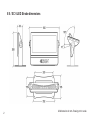
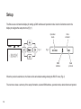
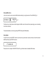
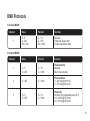
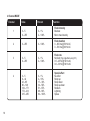
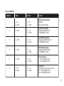
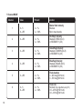
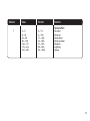
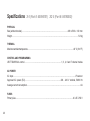
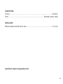
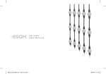
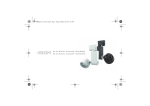
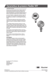
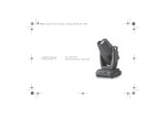
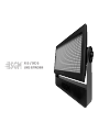
X·5 / XC·5
LED STROBE
X·5 / XC·5 LED Strobe dimensions
2
All dimensions in mm. Drawing not to scale.
X·5 / XC·5 LED STROBE
USER MANUAL REV. 1
© 2010-2012 SGMTM. Information subject to change without notice. SGM and all affiliated
companies disclaim liability for any injury, damage, direct or indirect loss, consequential
or economic loss or any other loss occasioned by the use of, inability to use or reliance
on the information contained in this manual. The SGM logo, the SGM name and all other
trademarks in this document pertaining to services or products by SGM or its affiliates and
subsidiaries are trademarks owned or licensed by SGM or its affiliates or subsidiaries.
X·5 / XC·5 LED Strobe uk
3
Contents
Safety Information....................................................................................................5
Preparation for Use...................................................................................................7
Controller Operation.................................................................................................9
Setup..............................................................................................................10
DMX Control Summary...........................................................................................12
Service......................................................................................................14
DMX Protocols........................................................................................................15
Specifications.........................................................................................20
Users notes.......................................................................................................................22
4
Safety Information
WARNING!
This product is for professional use only! It is not for household use.
Strobe lights are known to trigger epileptic seizures in persons who are photosensitive.
To guard against electric shock.
• Do not open: there are no user-serviceable parts inside.
• Always ground (earth ) the fixture electrically.
• Use only a source of AC power that compiles with local building and electrical codes and has both overload and
earth leakage protection.
• Do not expose the fixture to rain or moisture.

5
To guard against UV radiation, burn, and fire.
• Do not stare directly into the light.
• Never attempt to bypass the fuse. Always replace defective fuses with ones of the specified type and rating.
• Verify that the power feed cable is rated for the current draw of all connected fixtures.
• Keep all combustible materials (for example fabric, wood, paper) at least 0.5 meters (20 inches) away from the
fixture. Keep flammable materials well away from the fixture.
• Provide a minimum clearance of 0.1 meters (4 inches) around air vents.
• Do not modify the fixture or install other than genuine SGM parts.
• Do not operate the fixture if the ambient air temperature (Ta) exceeds 40˚ C (104˚ F).
To guard against epileptic seizure..
• Do not operate the fixture near stairways.
• Provide advance notice that strobe lighting is in use.
• Avoid extended periods of continuous flashing, particularly at frequencies of 10 to 20 flashes per second.
6
Preparation for Use
Unpacking
• Strobe Light Fixture
• User manual
• Mains power cable
• Foot − black aluminium plate
The packing material protects the fixture during shipment, please retain for future transportation of the fixture.
AC Power Connection
The auto-ranging power supply automatically adjusts to AC power from 200-240 volts nominal at 50/60 Hz.
The current required by the X-5/XC-5 is 4 amps. To avoid overload, allow one 4 amp branch circuit per fixture to
operate the X-5/XC-5 model at full power.
Use 2.5 mm2 (13 AWG) or larger power feed cables and keep runs as short as possible.
7
To rig the fixture
Always use a secure means of secondary fixing such as a safety wire
Before installing, verify that;
• the attachment hardware is in good condition and designed to carry at least 10 times the fixture’s weight,
• the structure can support at least 10 times the weight of all installed fixtures, clamps, cables, auxiliary equipment, etc.;
• the clearance around the air vents is at least 0.1 meters (4 in.).
• Loosen the mounting bracket and adjust the fixture to the desired angle.
• Connect and arrange the power and data cables.
8
Controller Operation
This section describes how to operate the X-5/XC-5 with a DMX controller.
Data Connection
The X-5/XC-5 provided 5-pin XLR sockets for data connection. The pin-out on all sockets is pin 1 to shield, pin
2 to cold (-), and pin 3 to hot (+). There is no connection to pins 4 and 5. The sockets are wired in parallel: both
inputs connect to both outputs. For reliable data transmission use one input and one output!
To connect the data link
1. Connect the DMX data input from the controller to the fixture 5-pin input (male) socket.
2. Connect up to 31 additional fixtures output-to-input.
3. Insert a termination plug in the output of the last fixture on the link.
Data Connection Tips
• Use shielded twisted-pair cable designed for DMX devices: standard microphone cable cannot transmit control
data reliably over long distance. 24 AWG cable is suitable for distances up to 300 meters (1000 ft.). Use heavier
gauge cable and/or a DMX splitter/amp for longer distances.
• Do not overload the link. Up to 32 devices may be connected on a serial link.
• Terminate the link by installing a termination plug in the output socket of the last fixture. The termination plug,
which is a male XLR plug with a 120 ohm, 0.25 watt resistor soldered between pins 2 and 3, absorb the control
signal so it does not reflect and cause interference.
9
Setup
The fixture uses an interactive display for setting up DMX address and operation mode. Use the five buttons next to the
display to navigate the setup structure (Fig. 1).
Operation
mode
Fig. 1
Data
indicator
Fig. 2
DMX
Address
Data
protocol
When the product is switched on, the fixture will be at its default setting showing the ROOT menu (Fig. 2).
The root menu show a summary of the setup information, selected DMX address, operation mode, data indicator and protocol.
10
Setting DMX address
In the root menu the user can set the DMX address directly by using the arrow UP and DOWN (Fig. 3).
Fig. 3
The fixture has a handy feature which displays the DMX value for the next fixture (assuming you are connecting
more than one fixture)
The selected address is stored by pushing ENTER storing the DMX address.
Setting Mode
To enter the menu press ENTER, and then use the arrow up and down to select sub menus. Select the desired
MODE and then press ENTER to store it.
Please refer to the chapter “DMX PROTOCOLS” to get further details of available DMX modes.
11
DMX Control Summary
For specific command values, see “DMX protocols” on page 15.
Intensity
Flash intensity can be set from minimum (blackout) to maximum on channel 1 in the 3- and 4-channel DMX
modes. Intensity is maximum in 1-channel DMX mode.
Duration
Flash duration can be set from 0 to 650 ms on 50 Hz power supplies, or 0 to 530 ms on 60 Hz power supplies, on
channel 2 in the 3- and 4-channel DMX modes. Flash duration is fixed in 1-channel DMX mode.
Rate
Flash rate can be set from 0 flashes per second to 25 flashes per second on 50 Hz power supplies or from 0 to 30
flashes per second on 60 Hz power supplies, on channel 3 in the 3- and 4-channel DMX modes. Flash rate is also
controllable in 1-channel DMX mode.
Programmed Effects
Six programmed effects are available on channel 4 in the 4-channel DMX mode only. The effects may be altered
using the intensity, duration, and rate controls.
12
• Ramp up: Light gradually increases in intensity, then blacks out.
• Ramp down: Light flashes to full intensity, then gradually fades.
• Ramp up-down: Light gradually increases and decreases.
• Random flash: Light flashes randomly with variable rate and intensity. Multiple units flash independently of each other.
• Lightning: The flashes simulate lightning. Duration is not adjustable.
Blinder Effect
The blinder effect, in which the light remains on for an extended period, is available in all DMX modes. In the 3and 4-channel modes, the effect is achieved
The combination of flash duration and rate prevents pauses between flashes. For example, the blinder effect can
be achieved with a flash duration of 0.25 seconds (250 ms) and a flash rate of 4 flashes per second, or a flash
duration of 0.05 seconds (50 ms) and a flash rate of 20 flashes per second.
In 3- and 4-channel DMX mode, the intensity of the blinder effect is controllable on channel 1. Lamp power is
electronically regulated to prevent the lamp from overheating. The intensity falls as power is reduced.
Single Flash
To trigger single flashes, start with the intensity and flash rate at 0 and then set intensity on channel 1. When the
value of channel 1 changes, the light will flash once with the programmed intensity, duration, and effect.
13
Service
Disconnect the product from the main power for at least a minute before servicing.
Fuse Replacement
The X-5/XC-5 uses a time-delay fuse for protection against current overload. The fuse is located inside the base
on the main PCB of the fixture – next to the low voltage power supply. Fuses must be replaced by a certified
professional.
Never bypass the fuse or replace it with one of another size or rating.
Firmware Updates
If you suspect that the firmware installed on your X-5/XC-5 becomes corrupted, please go to SGM website for
further information on how to update firmware or contact your nearest dealer for assistance.
14
DMX Protocols
1 Channel MODE
Value
Percent
Function
0-5
6 - 249
250 - 255
0 – 1%
2 – 97%
98 – 100%
Blackout
Flash rate, slow to fast
Continuous blinder effect
Value
Percent
Function
1
0–5
6 – 255
0 – 1%
2 – 100%
Flash intensity
Blackout
Min to max intensity
2
0 – 255
0 – 100%
Flash duration
0 – 650 ms @ 50 Hz AC
0 – 530 ms @ 60 Hz AC
3
0–5
6 – 255
0 – 1%
2 – 100%
Flash rate
No flash (Trig single flash using Ch1)
0.5 – 25 Hz @ 50 Hz AC
0.6 – 30 Hz @ 60 Hz AC
Channel
1
3 Channel MODE
Channel
15
4 Channel MODE
Channel
16
Value
Percent
Function
Flash intensity
Blackout
Min to max intensity
1
0–5
6 – 255
0 – 1%
2 – 100%
2
0 – 255
0 – 100%
Flash duration
0 – 650 ms @ 50 Hz AC
0 – 530 ms @ 60 Hz AC
3
0–5
6 – 255
0 – 1%
2 – 100%
Flash rate
No flash (Trig single flash using Ch1)
0.5 – 25 Hz @ 50 Hz AC
0.6 – 30 Hz @ 60 Hz AC
4
0–5
6 – 42
43 – 85
86 – 128
129 – 171
172 – 214
215 – 255
0 – 1%
2 – 16%
17 – 33%
34 – 50%
51 – 67%
68 – 83%
84 – 100%
Special effect
No effect
Ramp up
Ramp down
Ramp up-down
Random
Lightning
Spikes
6 Channel MODE
Value
Percent
1
0–5
6 – 255
0 – 1%
2 – 100%
Master flash intensity
Blackout
Min to max intensity
2
0 – 255
0 – 1%
2 – 100%
Red/Seg1 intensity
Intensity of RED (XC-5)
or SEGMENT 1 (X-5)
3
0 – 255
0 – 1%
2 – 100%
Green/Seg2 intensity
Intensity of GREEN (XC-5)
or SEGMENT 2 (X-5)
4
0 – 255
0 – 1%
2 – 100%
Blue/Seg3 intensity
Intensity of BLUE (XC-5)
or SEGMENT 3 (X-5)
5
0 – 255
0 – 1%
2 – 100%
Flash duration
0 – 650 ms @ 50 Hz AC
0 – 530 ms @ 60 Hz AC
6
0–5
6 – 255
0 – 1%
2 – 100%
Channel
Function
Flash rate
No flash (Trig single flash using Ch1)
0.5 – 25 Hz @ 50 Hz AC
0.6 – 30 Hz @ 60 Hz AC
17
7 Channel MODE
Value
Percent
1
0–5
6 – 255
0 – 1%
2 – 100%
Master flash intensity
Blackout
Min to max intensity
2
0 – 255
0 – 1%
2 – 100%
Red/Seg1 intensity
Intensity of RED (XC-5)
or SEGMENT 1 (X-5)
3
0 – 255
0 – 1%
2 – 100%
Green/Seg2 intensity
Intensity of GREEN (XC-5)
or SEGMENT 2 (X-5)
4
0 – 255
0 – 1%
2 – 100%
Blue/Seg3 intensity
Intensity of BLUE (XC-5)
or SEGMENT 3 (X-5)
5
0 – 255
0 – 1%
2 – 100%
Flash duration
0 – 650 ms @ 50 Hz AC
0 – 530 ms @ 60 Hz AC
6
0–5
6 – 255
0 – 1%
2 – 100%
Channel
18
Function
Flash rate
No flash (Trig single flash using Ch1)
0.5 – 25 Hz @ 50 Hz AC
0.6 – 30 Hz @ 60 Hz AC
Channel
7
Value
Percent
Function
0–5
6 – 42
43 – 85
86 – 128
129 – 171
172 – 214
215 – 255
0 – 1%
2 – 16%
17 – 33%
34 – 50%
51 – 67%
68 – 83%
84 – 100%
Special effect
No effect
Ramp up
Ramp down
Ramp up-down
Random
Lightning
Spikes
19
Specifications
X·5 (Part #: 80090001) XC·5 (Part #: 80090002)
PHYSICAL
Size (without bracket)………................................................................…………………………268 x 500 x 120 mm
Weight………………………………………………………….........................................................……..........……5.8 kg
THERMAL
Maximum ambient temperature…………………………….......................................................................40° C (104° F)
CONTROL AND PROGRAMMING
USITT DMX512-A control………………....................................................................1, 3, 4, 6 and 7 channel modes
AC POWER
AC input……………………………………………………………....................................................................Powercon
Approved AC power (EU)………………….............................................................200 - 240 V nominal, 50/60 Hz
Average current consumption……………………………………………....................................................................4 A
FUSES
Primary fuse……………………………………………………...................................................................6.3 AT / 250 V
20
CONSTRUCTION
Housing…………………………………………………………….................................................Aluminium
Finish…………………………………………...................................................................Electrostatic powder coating
INSTALLATION
Minimum clearance around fan and air vents………………….................................................................0.1 m (4 in)
Specifications subject to change without notice
21
Users notes
22
23
SGM A/S · Soeren Frichs Vej 51-53 · DK 8230 Aabyhoej · Denmark
Tel +45 70 20 74 00 · [email protected] · www.sgmlight.com