1
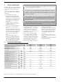
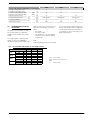
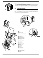
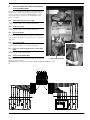
Italiano ANLI R410A MANUALE NSTALLAZIONE - MANUTENZIONE AXIAL UCONTRO OD L M Refrigeratori e pompe di calore aria acqua con compressori scroll SCROLL CHILLERS AND HEAT PUMPS INVERTER - Installation Maintenance Manual REFROIDISSEURS ET POMPES À CHALEUR INVERTER - Manuel d'installation et de maintenance KALTWASSERSÄTZE UND WÄRMEPUMPEN INVERTER - Installations- und Wartungsanleitung ENFRIADORAS Y BOMBAS DE CALOR INVERTER - Manual de instalación y mantenimiento ANLI H IANLIXI. 6755580_02 11/04. replace 6755580_01 09/06 Dear Customer, Thank you for choosing an AERMEC product. This product is the result of many years of experience and in-depth engineering research, and it is built using top quality materials and advanced technologies. Moreover, the CE mark guarantees that our appliances fully comply with the requirements of the European Machinery Directive in terms of safety. We constantly monitor the quality level of our products, and as a result AERMEC products are synonymous with Safety, Quality, and Reliability. Product data may be subject to modifications deemed necessary for improving the product without the obligation to give prior notice. Thank you again. AERMEC S.p.A AERMEC S.p.A. reserves the right at any moment to make any modifications considered necessary to improve our products and is not obliged to add these modifications to machines that have already been fabricated, delivered or are under construction. 2 1.1. 1.2. General warnings .....................................................6 Preservation of the documentation ...........................6 Warnings regarding safety and installation standards ..........................................6 2. Selection and place of installation ......................7 3. Positioning..................................................................7 4. Internal hydraulic circuit ........................................8 5. External hydraulic circuit ANLI (not provided) .8 6. Loading the system .................................................8 7. Emptying the system ...............................................8 8. Dimension tables ands hydraulic fitting positions.........................................................9 1. 9. 9.1. 9.2. 9.3. 9.4. 9.5. Electric connections................................................12 Electric data in cooling mode ...................................12 Recommended electric cable section ......................13 Electric control board ................................................14 Electric power connection ........................................14 Auxiliary connections under the responsibility of the user/installer ......................15 10. 10.1. 10.2. 10.3. Control and commissioning .................................16 Preparation for commissioning ................................16 Machine commissioning ...........................................16 Season changeover ....................................................16 11. 11.1. 11.2. 11.3. 11.4. 11.5. 11.6. 11.7. Functioning features ..............................................17 Set point in cooling mode ........................................17 Set point in heating mode ........................................17 Compressor start-up delay........................................17 Circulation pump .......................................................17 Fan speed control (DCPX accessory) ........................17 Anti-freeze alarm .......................................................17 Water flow rate alarm ...............................................17 12. Maintenance ............................................................17 12.1. Extraordinary maintenance .......................................18 13. List of controls for the guided procedure ........19 14. Anomalies .................................................................21 3 AERMEC S.p.A. I-37040 Bevilacqua (VR) Italy – Via Roma, 996 Tel. (+39) 0442 633111 Telefax 0442 93730 – (+39) 0442 93566 www . aermec . com - info @ aermec . com ANLI SERIAL NUMBER CE DECLARATION OF CONFORMITY We, the undersigned, hereby declare under our own responsibility that the assembly in question, defined as follows: NAME ANLI 020H - 025H - 070H TYPE WATER/AIR chiller, heat pump MODEL To which this declaration refers, complies with the following harmonised standards: CEI EN 60335-2-40 Safety standard regarding electrical heat pumps, air conditioners and dehumidifiers CEI EN 61000-6-1 CEI EN 61000-6-3 Immunity and electromagnetic emission for class B residential environment for ANLI 020H, class A for ANLI 070H CEI EN 61000-6-2 CEI EN 61000-6-4 Immunity and electromagnetic emissions for industrial environments CEI EN 61000-3-2 (ANLI 020H) Limits for the emission of harmonic currents CEI EN 61000-3-11 Limitation of voltage variations, the voltage fluctuations and the flicker in public low voltage power supply systems CEI EN 61000-3-12 (ANLI 070H) Limits for the emission of harmonic currents Therefore complying with the essential requirements of the following directives: - LVD Directive: 2006/95/CE - Directive for electromagnetic compatibility 2004/108/CE The person authorized to construct the technical file: Massimiliano Sfragara 37040 Bevilacqua (VR) Italy - Via Roma, 996 Bevilacqua 28/12/2009 Sales Director Signature 4 AERMEC S.p.A. I-37040 Bevilacqua (VR) Italy – Via Roma, 996 Tel. (+39) 0442 633111 Telefax 0442 93730 – (+39) 0442 93566 www . aermec . com - info @ aermec . com ANLI SERIAL NUMBER CE DECLARATION OF CONFORMITY We, the undersigned, hereby declare under our own responsibility that the assembly in question, defined as follows: NAME ANLI 100H TYPE WATER/AIR chiller, heat pump MODEL To which this declaration refers, complies with the following harmonised standards: CEI EN 60335-2-40 Safety standard regarding electrical heat pumps, air conditioners and dehumidifiers CEI EN 61000-6-1 CEI EN 61000-6-3 Immunity and electromagnetic emissions for residential environments CEI EN 61000-6-2 CEI EN 61000-6-4 Immunity and electromagnetic emissions for industrial environments CEI EN 61000-3-11 Limitation of voltage variations, the voltage fluctuations and the flicker in public low voltage power supply systems CEI EN 61000-3-12 Limits for the emission of harmonic currents EN378 Refrigerating systems and heat pumps - Safety and environmental requirements EN12735 Copper and copper alloys - Seamless, round copper tubes for air conditioning and refrigeration UNI 12735 Seamless, round copper tubes for air conditioning and refrigeration UNI 14276 Pressure equipment for cooling systems and heat pumps Therefore complying with the essential requirements of the following directives: - LVD Directive: 2006/95/CE - Directive for electromagnetic compatibility 2004/108/CE - Machinery Directive 2006/42CE - PED Directive regarding pressurised devices 97/23/CE The product, in agreement with Directive 97/23/CE, satisfies the Total quality Guarantee procedure (form H) with certificate n.06/270-QT3664 Rev.5 issued by the notified body n.1131 CEC via Pisacane 46 Legnano (MI) - Italy The person authorized to construct the technical file: Massimiliano Sfragara 37040 Bevilacqua (VR) Italy - Via Roma, 996 Bevilacqua 28/12/2009 Sales Director Signature 5 1. GENERAL WARNINGS Standards and Directives respected on designing and constructing the unit: Safety: Machinery Directive 98/37/CE Low Voltage Directive LVD 2006/95/CE Electromagnetic compatibility Directive EMC 2004/108/CE Pressure Equipment Directive PED 97/23/CE EN 378, UNI EN 14276 Electric part: EN 60204-1 Protection rating IP24 Acoustic part: ISO DIS 9614/2 (intensimetric method) Certifications: Eurovent x ANLI 020H Performance data: UNI EN 14511 Refrigerant GAS: This unit contains fluoride gases with greenhouse effect covered by the Kyoto Protocol. Maintenance and disposal must only be performed by qualified staff. R410A GWP=1900 AERMEC ANLs are constructed according to the recognised technical standards and safety regulations. They have been designed for air conditioning and the production of domestic hot water (DHW) and must be destined to this use compatibly with their performance features. Any contractual or extracontractual liability of the Company is excluded for injury/damage to persons, animals or objects owing to installation, regulation and maintenance errors or improper use. All uses not expressly indicated in this manual are prohibited. 1.1. or other elevation systems that may become necessary for carrying out servicing under warranty. Do not modify or tamper with the chiller as dangerous situations can be created and the manufacturer will not be liable for any damage caused. The validity of the warranty shall be void in the event of failure to comply with the above-mentioned indications. 1.2. −The chiller must be installed by a qualified and suitably trained technician, in compliance with the national legislation in force in the country of destination (Ministerial Decree 329/2004). AERMEC will not assume any responsibility for damage due to failure to follow these instructions. PRESERVATION OF THE DOCUMENTATION The instructions along with all the related documentation must be given to the user of the system, who assumes the responsibility to conserve the instructions so that they are always at hand in case of need. Read this sheet carefully; the execution of all works must be performed by qualified staff, according to Standards in force ion this subject in different countries. (Ministerial Decree 329/2004). The appliance must be installed in such a way as to enable maintenance and/or repairs to be carried out. The appliance warranty does not cover the costs for ladder trucks, scaffolding, WARNINGS REGARDING SAFETY AND INSTALLATION STANDARDS − Before beginning any operation, READ THESE INSTRUCTIONS CAREFULLY AND CARRY OUT THE SAFETY CHECKS TO REDUCE ALL RISK OF DANGER TO A MINIMUM. All the staff involved must have thorough knowledge of the operations and any dangers that may arise at the moment in which the installation operations are carried out. Danger! The refrigerant circuit is under pressure. Moreover, very high temperatures can be reached. The appliance may only be opened by an SAT service technician or by a qualified technician. Work on the cooling circuit may only be carried out by a qualified refrigeration technician. R410A REFRIGERANT GAS The cooler comes supplied with a sufficient quantity of R410A refrigerant gas. This refrigerant is chlorine-free and does not damage the ozone layer. R410A is not flammable. However, all maintenance operations must be carried out exclusively by a specialised technician using suitable protective equipment. Danger of electrical discharge! Before opening the heat pump, completely disconnect the appliance from the power mains. 6 FOR THE INSTALLER 2. Before beginning installation consent with client and pay attention to the following recommendations: − − − 3. 150 SELECTION AND PLACE OF INSTALLATION The support surface must be capable of supporting the unit weight. The safety differences between the unit and other appliances or structures must be scrupulously respected so that the inlet and outlet air from the fans is free to circulate. The unit must be installed by an enabled technician in compliance with the national legislation in force in the country of destination, respecting the minimum technical spaces in order to allow maintenance. POSITIONING Before handling the unit, verify the lifting capacity of the machines used, respecting the indications given on the packaging. To handle the machine (ANLI 020H -070H) on horizontal surfaces, se fork lift trucks or similar in the most appropriate manner, paying attention to the distribution of the unit weight. 200 In the case of lifting (ANLI 100H), insert pipes into the holes supplied on the base (NOT SUPPLIED).The length of the pipes must be such to allow positioning of the lifting belts and relative safety pins. Position the unit in the place indicated by the customer, placing a rubber covering between the base and the support (min. thickness 10 mm.) or alternatively anti-vibrating feet (ACCESSORIES). For further information, refer to the dimensional tables Free 500 field ANLI 020H 200 300 Fix the unit checking that it is level. Make sure that the hydraulic and electric part can be easily reached. In case of installation in places where gusts of wind are frequent, fix the unit suitably using tie-rods. Envision the installation of the condensate drain tray in the versions where envisioned (as ACCESSORY). 500 Free field ANLI 070H 800 800 800 ANLI 100H 1100 7 HYDRAULIC CIRCUIT EXAMPLE Te diagram shown IS ONLY AN EXAMPLE 4. INTERNAL HYDRAULIC CIRCUIT The internal hydraulic circuit of the ANLI is made up according to the version: 4 6 2 Standard version − Fitted water filter − Differential pressure switch − Plate heat exchanger − Water inlet/outlet probes (SIW-SUW) Versions P/X with pump − Fitted water filter − Discharge tube − Safety valve − Circulator/Pump − Differential pressure switch − Plate heat exchanger − Water inlet/outlet probes (SIW-SUW) − Expansion vessel 1 5. 3 5 version P - X KEY 1 Circulator/pump 2 Differential pressure switch 3 Safety valve 4 Expansion vessel 5 Water filter 6 Plate heat exchanger PH Electric conductivity Chloride ions Sulphuric acid ions Total iron Alkalinity M Total hardness Sulphur ions ammonia ions Silicone ions 8 6-8 less than 200 mV/cm (25°C) less than 50 ppm less than 50 ppm less than 0,3 ppm less than 50 ppm less than 50 ppm none none less than 30 ppm EXTERNAL HYDRAULIC CIRCUIT ANLI (NOT PROVIDED) The choice and the installation of components external to the ANLI is up to the installer, who must operate according to the rules of good technical design and in compliance with the regulations in force in the country of destination (Ministerial Decree 329/2004). Before connecting the pipes make sure that they do not contain stones, sand, rust, sludge or foreign bodies that could damage the system. It is good practice to realise a unit by-pass to be able to wash the pipes without having to disconnect the appliance. The connection piping must be adequately supported so that its weight is not borne by the appliance. It is recommended to install the following tools on the evaporator water circuit, whenever not envisioned in the version in your possession: 1. two manometers with suitable scale (in inlet and outlet). 2. Two anti-vibration joints (in inlet and in outlet). 3. Two cut-off valves (in normal input, in calibration valve output). 4. two thermometers (in inlet and in outlet). 5. Pump (if not supplied with the machine) 6. Expansion vessel (if not supplied with the machine) 7. Safety valve (if not supplied with the machine It is necessary that the cooling unit water flow rate is in compliance with the values given in the performance tables. For correct unit functioning in the applications with variable water flow rate, a minimum flow rate must be assured that is equal to 35% of the catalogue nominal flow rate The systems loaded with anti-freeze or particular legal dispositions, make the use of water disconnectors mandatory. Supply/reintegration water details must be conditioned with appropriate treatment systems. 6. − − − − − LOADING THE SYSTEM Before starting loading, check that the system drain cock is closed. Open all system vent valves and relative terminals. Open the system cut-off devices. Start filling by slowly opening the system water loading cock outside the appliance. When water starts to escape from the terminal vent valves, close them and continue loading until the value of 1.5 bar is read on the manometer. The system must be loaded at a pressure between 1 and 2 bar. It is recommended to repeat this operation after the appliance has functioned for a few hours and to periodically check the system pressure, reintegrating it if it falls below 1 bar. Check the hydraulic sealing of the joints. 7. − EMPTYING THE SYSTEM Before beginning emptying, place the master switch at "OFF" − Check that loading/water system reintegration cock is closed − Open the drain cock outside the appliance and all system vent valves and relative terminals. If anti-freeze is used by the unit, it must not be dumped as it is harmful to the environment. It should be collected and if possible reused. If discharge takes place after functioning in heat pump mode, pay attention to the temperature of the water (also about 55°C). 8. DIMENSION TABLES ANDS HYDRAULIC FITTING POSITIONS 8.2.1. ANLI 020H - HP - HX 310 900 868 OUT 1”¼ 194 97 OUT 1”¼ IN1”¼ IN 1”¼ 69 354 113 895 122,50 122,50 650 330 Ø9 B C D Mod. A B C D VT9 40 30 23 M8 ANLI MOD. VERS. WEIGHT 020 020 H H ° P/X 70 72 KIT VT 9 9 A 9 8.2.2. ANLI 070 H - HP - HX 384 1124 1252 OUT 1”¼ 190 100 IN1”¼ OUT 1”¼ 428 IN1”¼ 67 1118 229 229 660 403 Ø 11 B C D A 10 Mod. A B C D VT9 40 30 23 M8 ANLI MOD. VERS. WEIGHT 070 070 H H ° P/X 134 141 KIT VT 9 9 8.2.3. ANLI 100 H - HP 1800 1750 1345 750 IN1”¼ 515 1590 80 20 D B 750 C 40 80 102 OUT 1”¼ Ø9 A Mod. VT15 ANLI MOD. VERS. WEIGHT 100 100 H H ° P/X 293 308 A 50 B 30 C 28,5 D 10 KIT VT 15 15 11 9. ELECTRIC CONNECTIONS All the electrical operations must be carried out by STAFF IN POSSESSION OF THE NECESSARY QUALIFICATIONS BY LAW suitably trained and informed on the risks related to these operations. The ANL chillers are completely wired at the factory and only require connection to the electrical mains, downstream from a to that envisioned by the Standards in force on this subject in the country of installation. It s also advised to check that: − − − − − 9.1. The characteristics of the electrical lines and of the related components must be determined by STAFF QUALIFIED TO DESIGN ELECTRICAL SYSTEMS, in compliance with the international and national regulations of the place of installation of the unit and in compliance with the regulations in force at the moment of installation the electrical mains features are suitable for the absorption values indicated in the electrical data table, also taking into consideration any other machines operating at the same time. The unit is only powered when installation has been completed (hydraulic and electric). Respect the connection indications of the phase, neutral and earth wires. The power supply line must have a relevant protection mounted upstream, which isolates the system with respect to other utilities, against short circuits and dispersions to earth. The voltage must be within a tolerance of ±10% of the nominal power supply voltage of the machine (for unbalanced three-phase unit max 3% between the phases). Whenever these parameters are For the installation requirements refer only to the electrical diagram supplied with the appliance. The electrical diagram along with the manuals must be kept in good condition and ALWAYS AVAILABLE FOR ANY FUTURE SERVICING ON THE UNIT. IT IS mandatory to verify that the machine is watertight before making the electrical connections and it must only be powered up after the hydraulic and electrical works have been completed. − not respected, contact the electric energy public body. For electric connections, use the cables with double isolation according to the Standards in force on this subject in the different countries. The use of an omnipolar magnet circuit breaker switch is mandatory, in compliance with the IEC-EN Standards (contact opening at least 3 mm), with suitable cut-off power and differential protection on the basis of the electric data table shown below, installed as near as − possible to the appliance. It is mandatory to make an effective earth connection. The manufacturer cannot be considered responsible for any damage caused by the lack of or ineffective appliance earth connection. For units with three-phase power supply, check the correct connection of the phases. It is prohibited to use the water pipes to earth the appliance. ELECTRIC DATA IN COOLING MODE Total input power when hot fancoil system Total input power when hot floor system H HP/HX H HP/HX H HP/HX Total input current when cold H Total input power when cold Total input current when hot fan coil system Total input current when hot fan coil system Total input current when hot floor system Total input current when hot floor system H HP/HX H HP/HX Maximum current (FLA) H Maximum current (FLA) HP/HX Peak current (LRA) H Peak current (LRA) HP/HX kW kW kW kW kW kW 400V 230V 400V 230V 400V 230V 400V 230V 400V 230V 400V 230V 400V 230V 400V 230V 400V 230V A A A 020H 2,12 2,14 2,08 2,10 1,72 1,74 10,3 - A A A A A A 10,8 14,0 14,5 20,0 21 NOTE: The ANLI 100 H size is not AVAILABLE with the pump with INVERTER "VERSION X" 12 − 070H 4,4 4,67/4,53 4,4 4,67/4,53 3,7 3,97/3,83 18,9 19,1 21,8/20,4 16,0 18,7/17,3 24,5 27,2/25,8 25,0 27,7/26,3 100H 11,5 12,25 11,1 11,85 9,5 10,25 16,3 15,7 17,1 13,4 14,8 21,0 22,4 30,0 31,4 - SAFETY AND CONTROL COMPONENTS ELECTRIC DATA Fan magnet circuit breakers MTV1 A Fan magnet circuit breakers MTV2 A Compressors magnet circuit breakers MTC1 230V A Compressors magnet circuit breakers MTC1 400V A High pressure pressure switch bar Low pressure pressure switch cold bar cold bar Low pressure transducer PdC bar High pressure transducer bar 9.2. RECOMMENDED ELECTRIC CABLE SECTION The cable sections stated in the table are recommended for a maximum length of 50 m and placed in a cable trough. For longer lengths or different cable laying, it is up to the PLANNER to calculate the appropriate length of the 020H 070H 100H 2 16 42 NOT PRESENT 4 2 40,5 2 2 21 42 NOT PRESENT 4 2 40,5 42 NOT PRESENT 4 2 40,5 cables as well as the connection to the earth wire and linking to connected cables: − the length − the type of cable − the absorption of the unit and the physical location, and the ambient temperature. ps on commissioning and after 30 days from start-up. Subsequently, check the tightening of all the power clamps every six months. Loose terminals can cause overheating of the cables and components. NOTE: Check the tightening of all power wire clam- 9.2.1. Recommended cable lengths for max. length of 50 mt SEC A SEC B Earth IL 230V 400V 230V 400V 230V 400V 230V 400V mm2 mm2 mm2 mm2 mm2 mm2 A A 020 4 0,5 4 25 - 070 4 0,5 4 16 - 100 - SEC A Power supply SEC B Remote control if present Earth IL Master switch 13 9.3. ELECTRIC CONTROL BOARD The electric control board is situated inside the machine. To access the electric control board and make the electric connections, in the sizes from 020 to 070 the upper and front panel must be removed, in size 100 act on the screw with ¼ of a turn and open the front panels. 9.4. ELECTRIC POWER CONNECTION For the functional connection of the unit take the power supply cable at the electric control board inside the unit fig.1 and connect to the isolator clamps respecting the phase, the neutral and the earth both in the case of single-phase (230V~50Hz), and three-phase power supply (400V-3N~50Hz). fig.2 Fig. 01 KEY 201 Bipolar switch 202 Door-lock isolating switch 203 Contactor 204 Unipolar automatic switch 205 Inverter kit protection 206 Transformer 207 Pressure transducer 209 Moducontrol Board 210 Door-lock handle 211 Condenser 212 Inverter filter board 213 NTC probe 216 Electric box 218 DCPX (accessory) 219 Network filter 220 Relay 221 Screw feet 226 Inverter 227 Controller EC3 228 Connectors kit 229 Electric fans 230 Filter board 231 Module board UNIT 232 Reactor 14 Fig. 02 9.5. AUXILIARY CONNECTIONS UNDER THE RESPONSIBILITY OF THE USER/INSTALLER All clamps to which reference is made in the following explanations are part of the 11 POLE terminal board situated inside the electric control board and connected to the MODUCONTROL, see figure. There are two types of connections, see wiring diagram at the bottom of the page: 9.5.1. Summer/Winter Remote Control (C/F) To prepare a summer/winter switch-over device, connect the device contact to clamps 3 and 5 of the 11 POLE terminal board, 9.5.2. On/Off Control (IA) To prepare a remote ON/OFF switch-over device, connect the device contact to clamps 4 and 5 of the 11 POLE terminal board, 9.5.3. Remote Alarm (AE) If it should be necessary to view the machine block, in a remote point, due to functioning anomaly, it is possible via clamps 6 and 7 of the 11 POLE terminal board. Connect an acoustic or visual alarm signal device. 9.5.4. Remote Panel (TRA) To prepare a summer/winter switch-over device, connect the device contact to clamps 8 and 9 of the 11 POLE terminal board, 9.5.5. Contact for thermostating domestic hot water DHW (TWS) To prepare a stand-alone thermostating device, connect to clamps 10 and 11 of the 11 POLE terminal board. 9.5.6. Connection PR3 (ACCESSORY) If you should have the PR3 accessory, always connect it to the 11 11 pole terminal board POLE terminal board as shown below. Remember that the maximum distance accepted is 150 mt. REMEMBER THAT THE PR3 AS WELL AS BEING CONNECTED MUST BE ENABLED see page 20 ATTENZIONE! 3.4 I morsetti 6 e 7 forniscono un'isolamento principale rispetto all'alimentazione della macchina, tutti gli altri forniscono un'isolamento rinforzato . 3.2 3.3 2.5 3.3 3.2 2.8 3.2 3.3 3.2 7 AE C/F TRA IA T T TWS 230V MAX 1A 15V 0V C/F SEZ. MIN. 0.5 mm² max 150m 6 5 4 3 2 1 TRA 0 1 T ALARM SEZ. MIN. 0.5 mm² max 150m AE-L COM IA AE-N M5S1-1 M5S1-2 M7S-7 M7S-5 M7S-8 M1S-8 M1-8 M7-5 M7-6 M7S-3 M7S-4 3.4 T TWS PR3 15 WARNING Commissioning must be performed with standard settings. Only when the inspection has been completed can the functioning Set Point values by changed. Before start-up, power the unit for at least 12-24 hours positioning the protection magnet circuit breaker switch and the door lock isolating switch at ON fig. 3 and then switch the control panel fig. 04 off in order to allow heating of the compressor sump oil. OFF ON Fig. 03 LED ( I ) off 10. CONTROL AND COMMISSIONING 10.1. PREPARATION FOR COMMISSIONING Please note that, on request by the Aermec customer or the legitimate owner of the machine, the units in this series can be started up by the AERMEC After-Sales Service in your area (valid only on Italian territory). The start of operation must be scheduled in advance based on the timeframe for the completion of works for the system. Prior to the work to be carried out by the AERMEC After-Sales Service, all other works (electrical and hydraulic connections, loading N and bleeding of air from the system) must have been completed. Before starting the unit make sure that: − All safety conditions have been respected − The unit is correctly fixed to the support surface − The minimum technical spaces have been respected; − The hydraulic connections have been made respecting the inlet and outlet − The hydraulic plant has been loaded and bled. − The hydraulic circuit cocks are open − The electric connections have been made correctly − The voltage is within the tolerance of 10% of the unit nominal value − The earth connection has been made correctly − All electric and hydraulic connections have been tightened well. 10.2. 0 MACHINE COMMISSIONING Before starting the unit: − Close the electric control board hatch. − Position the appliance master switch at ON. (fig.3) − Make sure that the auxiliary switch contact (IA) (see wiring diagram) is open (if used) and the LED (I) A display must be off fig 4. − Press the ON key for 3 sec to switch the machine on. ON/OFF Fig. 04 10.3. − − − 16 SEASON CHANGEOVER For every season change, check that the functioning limits lie within the limits. Check that the compressor input current is lower than the maximum indicated in the technical data table. Check, that in models with three-phase − power supply, that the compressor noise level is not abnormal. If this is the case, invert a phase. Make sure that the voltage value lies within the pre-fixed limits and that unbalance between the three phases (three-phase power supply) is not above 3%. 10.3.1. Season changeover from panel on machine Access the USER SET list by touching the key, insert the password 000 (already displayed; just confirm by re-pressing the key. The parameter affected is the 0 For further information refer to the USER manual CODE Sta NAME Season Min 0 Default 0 Max Meaning 1 0 functioning in cooling mode 1 functioning in heating mode 10.3.2. Season changeover from PR3 − Just act directly on the switch The machine switches off automatically and switches back-on with the selected functioning mode 11. FUNCTIONING FEATURES 11.1. SET POINT IN COOLING MODE (factory set) = 7°C, t = 5°C. 11.2. SET POINT IN HEATING MODE (factory set) = 45°C, t = 5°C. If the unit power supply is restored after a temporary interruption, the set mode will be kept in the memory. 11.3. COMPRESSOR START-UP DELAY Two functions have been prepared to prevent compressor start-ups that are too close. − − Minimum time from last switch-off 180 seconds. Minimum time from last switch-on 300 seconds. 11.4. CIRCULATION PUMP The circuit board envisions an output for pump management, which starts on commissioning and remains on for at least 150 seconds and controls the state of the probes. After the first 40 seconds that the pump functions, when the water flow rate is in normal working conditions, the water flow rate alarm functions are activated (differential pressure switch or flow meter). When the machine enters stand-by mode, the pump remains on for 30 sec and controls the flow meter or the pressure switch 12. MAINTENANCE All cleaning is prohibited until the unit has been disconnected from the electric power supply mains. Make sure there is no voltage present before operating. Periodic maintenance is fundamental to keep the unit perfectly efficient under a functional and energetic point of view. It is therefore essential to carry out periodic yearly controls for the: 12.7.1. Hydraulic circuit − Refilling of water circuit − Clean the water filter. − Control of flow switch/pressure switch − Bleed the air from the circuit. − Verify that the water flow rate to the evaporator is constant. − Verify the thermal insulation of the hydraulic piping. − Check the percentage of glycol where necessary 11.5. FAN SPEED CONTROL (DCPX ACCESSORY) To allow correct functioning of the unit at different external temperatures, the MODUCONTROL by reading the pressure via the pressure probe, controls the rotation speed of the fans, thus allowing to increase and/or decrease heat exchange, keeping the condensation or evaporation pressures more or less constant. The fan functions independently with respect to the compressor. Remember that for the production of DHW, the DCPX is mandatory ONLY FOR ANLI 020H. For ANLI 070 and 100 H the production of DHW must be performed without the DCPX in order to prevent unit blocks causing overheating of the INVERTER compressor. 11.6. ANTI-FREEZE ALARM compressor block and not pump block, which remains active along with the switchon of the resistance if installed. To restore normal functions the temperature of the outlet water must rise above +4°C. Rearm is manual. WHENEVER THIS ALARM INTERVENES, WE ADVISE YOU CALL THE NEAREST AFTER-SALES SERVICE IMMEDIATELY. 11.7. WATER FLOW RATE ALARM The MODUCONTROL manages a water flow rate alarm controlled by the differential pressure switch installed in series on the machine. This type of safety device intervenes after the first 40 seconds of pump functioning, if the water flow rate is not sufficient. The intervention of this alarm determines compressor and pump block. The anti-freeze alarm is never active if the machine is off or in stand-by mode. In order to prevent breakage of the plate heat exchanger due to freezing of the water it contains, the MODUCONTROL blocks the compressor and ignition of the resistance (ACCESSORY) if the temperature detected by the probe positioned at the outlet of the heat exchanger and in inlet to the chiller is below +4°C. THIS ANTI-FREEZE SET TEMPERATURE CAN ONLY BE VARIED BY AN AUTHORISED AFTER-SALES CENTRE AND ONLY AFTER HAVING CHECKED THAT THERE IS ANTI-FREEZE SOLUTION IN THE WATER SYSTEM. The intervention of this alarm determines 12.7.2. Electric circuit checks − Safety efficiency − Electric supply pressure − Electrical Input − Connection tightness − Verify the operation of the carter compressor resistance 12.7.3. Cooling circuit checks − State of compressor − Efficiency of the plate heat exchanger resistance if envisioned − Work pressure − Leak test for watertightness control of the cooling circuit − Functioning of high and low pressure pressure switches − Carry out the appropriate checks on the filter dryer to check efficiency WARNING Inspection, maintenance and eventual repair work must be carried out only by a legally qualified technician. Lack of control/maintenance can cause damage to persons or things. For appliances installed near to the sea, the maintenance intervals must be halved. 12.7.4. Mechanical checks Check the tightening of the screws the compressors and the electrical box, as well as the exterior panelling of the unit. Insufficient fastening can lead to − 17 We recommend to envision a machine book (not supplied, but the user's responsibility), which allows to keep track of the interventions performed on the unit. In this way it will be easy to suitably organise the interventions making research and the prevention of any machine breakdowns easier. Use the date to record date, type of intervention made (routine maintenance, inspection or repairs), description of the intervention, measures actuated… IT IS forbidden to RELOAD the circuit with a refrigerant gas different to the one indicated. Using a different refrigerant gas can cause serious damage to the compressor. DISPOSAL Envisions that disposal of the unit is carried out in conformity with the Standards in force in the different countries 18 − undesired noise and vibrations. Check the condition of the structure. If there are any oxidised parts, treat with paint suitable to eliminate or reduce oxidation. 12.1. EXTRAORDINARY MAINTENANCE the ANLIs are filled with R410A gas and are inspected at the factory. Under normal conditions they do not require Technical Assistance related to control of refrigerant gas. Through time gas leakage may be generated from the joints, causing refrigerant to escape and discharge the circuit, causing appliance malfunctioning. In these cases the leakage points are to be discovered, repaired and the Gas circuit is to be replenished, respecting the December 28 1993 n°549 law. 12.1.1. Load procedure The load procedure is the following: − Empty and dry the entire cooling circuit using a vacuum pump connected to the low and high pressure socket until 10 − − − − − − Pa is read on the vacuum meter. Wait a few minutes and check that this value does not rise above 50 Pa. Connect the refrigerant gas cylinder or a load cylinder to the socket on the low pressure line. Load the amount of refrigerant gas indicated on the appliance features plate. The R410A refrigerant must only be loaded in the liquid state. Functioning conditions that are different to the nominal conditions can give rise to values that are greatly different. The sealing test or the search for leaks must only be performed using R410A refrigerant gas, checking using a suitable leak detector. In the cooling circuit it is prohibited to use oxygen or acetylene or other inflammable or poisonous gases because they are a cause of explosions or intoxication. 13. LIST OF CONTROLS FOR THE GUIDED PROCEDURE Some parameters in the moducontrol board must be set appropriately on the basis of the type of system in which the unit is installed. These modifications, performed by the installer, are summarised and organised in the following guided procedures, with which to correctly set the unit circuit board parameters. How to modify a parameter in the user menu: To enter the USER menu press the key shown in (Fig.A). Once the key has been pressed the password must be inserted for access to the various menus. To access the user menu the password is 000 (which is the default displayed); to modify the value of the password use the arrow keys. Once the correct password has been inserted, press the key shown in (Fig.A). The display shows the index of the USER parameter and a string of three characters that identify it. The string re- mains displayed for one second, after which it is replaced by the value relative to the parameter itself. To pass to the next parameter, use the arrow keys (Fig.B). To modify a parameter, just select it, press the key shown in (Fig.A), modify the value using the arrow keys shown in (Fig.B). To confirm the modification press the key shown in (Fig.A) again. R PASSWORD = 000 Fig.A R Fig.B How to modify a parameter in the installer menu: To enter the INSTALLER menu, press the key shown in (Fig.A). Once the key has been pressed the password must be inserted for access to the various menus. To access the user menu the password is 030. To modify the value of the password use the arrow keys. Once the correct password has been inserted, press the key shown in (Fig.A). The display shows the index of the INSTALLER parameter and a string of three characters that identify it. The string remains displayed for one second, after which it is replaced by the value relative to the parameter itself. To pass to the next parameter, use the arrow keys (Fig.B). To modify a parameter, just select it, press the key shown in (Fig.A), modify the value using the arrow keys shown in (Fig.B). To confirm the modification press the key shown in (Fig.A) again. R PASSWORD = 030 Fig.A R Fig.B 19 (1) What type of system terminals are used in the heating circuit? Reply Is the unit a cooling only model Radiant panels (floor, etc....) Fan coils or low temperature radiators Other applications Operations to be performed Go to question 2 Set the parameter StC (index 3 USER menu) with the value of 35 °C Set the parameter StC (index 3 USER menu) with the value of 45 °C (default value) Set the parameter StC (index 3 USER menu) with the value of 55 °C (2) Is the remote panel accessory installed (PR3)? Reply Not installed Operations to be performed Go to question 3 Set the parameter PAN (index 9 INSTALLER menu) with the appropriate value selecting from: Value (1): • Season control piloted from the circuit board • ON/OFF control enabled from PR3 Installed Value (2): • Season control enabled from PR3 • ON/OFF control from panel on machine Value (3): • Season control enabled from PR3 • ON/OFF control enabled from PR3 (3) Is the production of DHW envisioned? Reply Not envisioned Envisioned Operations to be performed Go to question 5 Set the parameter ASA (index A INSTALLER MENU) with the value (1) (4) Is a 3-way diverter valve envisioned in the DHW production circuit? Reply Not envisioned Operations to be performed Go to question 5 Set the parameter AAS (index C INSTALLER menu) with the appropriate value (in seconds). This parameter indicates the stand-by time for inversion of the 3-way diverter valve on the DHW production system Envisioned (5) Is a room thermostat installed? Reply Not installed Installed Operations to be performed No operation This parameter enables a digital clamp ID (indicated on the circuit board with the code TRA) to which a room thermostat must be connected, used to disable the compressors and the integrative resistances. Set the parameter trA (index D INSTALLER menu) with the appropriate value, selecting from: Value (1 or 2): Clamp ENABLED Value (0 or 3): Clamp DISABLED Remember that the OPEN state on the clamp represents: • the compressors and resistances block function if the parameter is set at 1 • the compressors, pumps and resistances block function if the parameter is set at 2 • represents the pump alarm (as in the previous software version), if the parameter is set at the value 3 For further information regarding operations that can be performed on the user and installer parameters, refer to the unit user manual. 20 14. ANOMALIES ANOMALY The chiller does not start-up Insufficient yield Noisy compressor Noise and vibrations The compressor stops due to intervention of the protections High discharge pressure Low discharge pressure High intake pressure CAUSE • No electric voltage • • • • • • • • • • • • • • • • • • • • • • • • • Master switch at OFF Remote switch at OFF (if present) Control panel at OFF Main switch at OFF Compressor magnet circuit breaker at OFF Power supply voltage too low Remote control switch coil broken Circuit board broken Peak condenser broken Compressor broken No refrigerant Appliance dimensioning Functioning outside of operational limits Liquid return to the compressor Inadequate fixing Phase inverted (in three-phase versions only) Contacts between metal bodies Weak rest Loose screws Excessive flow pressure Low intake pressure Power supply voltage low Electric connections fastened badly Functioning outside of operational limits Pressure switch functions badly • Circuit breaker protection intervention • • • • • • • • • • • High external air temperature High water input temperature Insufficient air flow Insufficient water flow Fan regulation anomalous functioning Air in the hydraulic system Excessive gas load Low external air temperature Low water input temperature Humidity in the cooling circuit Anomalous functioning of fan regulation (if envisioned) Air in the hydraulic system Insufficient gas load High external air temperature High water input temperature Thermostatic expansion valve too open or damaged Low external air temperature Low water input temperature Thermostatic expansion valve damaged or blocked Water filter blocked Plate heat exchanger blocked Insufficient air flow Insufficient water flow • • • • • • • • Low intake pressure • • • • REMEDY • Check the presence of voltage • Check the safety systems upstream from the appliance • Position at ON • Check power supply line • Replace the component • Check • Check • • • • Invert a phase Check Restore Tighten the screws • Check • • • Replace the component Check power supply voltage Check electric isolation of the windings • Check • • • • • Check fan functioning Check pump functioning Check Bleed Check • Check • Empty and restore the gas load • Check • • Bleed Check • Check • Check • • Check fan functioning Check pump functioning 21