1
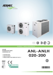
M
L
AXIAL
UCONTRO
OD
SCROLL
HEAT PUMPS - Technical - Installation manual
HEAT PUMP
ANL 100-150HA
• EXTERNAL UNIT
• HIGH EFFICENCY
• HOT WATER PRODUCING UP TO 122°F / 50°c
• POWER SUPPLY 60Hz
60Hz
en
IANL60HzPY. 1205. 6755517_02
Dear Customer,
Thank you for choosing an AERMEC product. This product is the result of many years of experience and indepth engineering research, and it is built using top quality materials and advanced technologies.
In addition, the CE mark guarantees that our appliances fully comply with the requirements of the European
Machinery Directive in terms of safety. We constantly monitor the quality level of our products, and as a result
they are synonymous with Safety, Quality, and Reliability.
Product data may be subject to modifications deemed necessary for improving the product without the obligation to give prior notice.
Thank you again.
AERMEC S.p.A
AERMEC S.p.A. reserves the right at any moment to make any modifications considered necessary to improve our products and is not obliged to add these modifications to
machines that have already been fabricated, delivered or are under construction.
INDEX
1.
Description and choce of unit........................................................6
2.
Product identification....................................................................6
3.
21.
21.1.
Dimensions..................................................................................29
Anl 100 - 150 h|hp|ha version.................................................... 29
Ceck list.........................................................................................6
22.
Antivibration positioning and distribution of percentage
on supporting points....................................................................29
4.
Configurator..................................................................................7
23.
Hydraulic connections..................................................................30
5.
Main cooling layout.......................................................................8
6.
6.1.
6.2.
6.3.
6.4.
6.5.
6.6.
Description of components............................................................9
Chiller circuit...................................................................................... 9
Frame and fans.................................................................................. 9
Hydraulic circuit standard components............................................. 9
Hydraulic components for configurable versions............................... 9
Safety and control components....................................................... 10
Electric components........................................................................ 10
24.
24.1.
24.2.
24.3.
Electrical data..............................................................................31
Compressor thermomagnetic.......................................................... 31
Pump thermomagnetic.................................................................... 31
Auxiliary thermomagnetic............................................................... 31
25.
25.1.
25.2.
25.3.
Strat-up.......................................................................................32
Preliminary operations to be made without tension....................... 32
The following operations are performed when the unit is powered..32
Machine commissioning.................................................................. 32
7.
Accessories compatibilty table.....................................................11
8.
Technical data .............................................................................12
9.
9.1.
9.2.
9.3.
Operating limits...........................................................................14
Cooling mode................................................................................... 14
Heating mode (for heating pump)................................................... 14
Project data...................................................................................... 14
26.
26.1.
26.2.
26.3.
26.4.
26.5.
26.6.
Functioning features....................................................................33
Set point in cooling mode................................................................ 33
Set point in riscaldamento............................................................... 33
Compressor start-up delay............................................................... 33
Circulation pump.............................................................................. 33
Anti-freeze alarm............................................................................. 33
Water flow rate alarm...................................................................... 33
10.
Performance in cooling mode......................................................15
10.1. Anl 100.......................................................................................... 15
10.2. Anl 150.......................................................................................... 15
10.3. Anl 100 hp-ha.............................................................................. 16
10.4. Anl 150 hp-ha.............................................................................. 16
11.
11.1.
11.2.
11.3.
11.4.
Performance in heating mode......................................................17
Anl 100 h....................................................................................... 17
Anl 150 h....................................................................................... 17
Anl 100 hp-ha.............................................................................. 18
Anl 150 hp-ha.............................................................................. 18
12.
11.5.
Ethylene glycol solutions..............................................................19
How to interpret glycol curves......................................................... 19
13.
13.1.
13.2.
Pressure drop..............................................................................20
System side - pressure drop only cooling version............................ 20
Water filter - pressure drop............................................................. 20
14.
Useful heads................................................................................21
15.
15.1.
15.2.
Storage tank..............................................................................22
Minimum/maximum content of system water ............................... 22
Expansion vessel calibration ........................................................... 22
16.
Sound data..................................................................................23
17.
Parameter calibration of safety and control.................................23
18.
18.1.
18.2.
General warnings for the installer................................................24
Preservation of the documentation................................................. 24
Warnings regarding safety and installation standards .................... 24
19.
Selection and place of installation................................................25
20.
20.1.
20.2.
20.3.
Hydraulic circuits of principle.......................................................26
Hydraulic circuit for internal and external anl "h" (standard)......... 26
Circuito idraulico interno ed esterno ad anl “hp"............................ 27
Hydraulic circuit for internal and external anl "ha"........................ 28
27.Maintenance...............................................................................34
27.2. Hydraulic circuit............................................................................... 34
27.3. Emptying the system........................................................................ 34
27.4. Electrical circuit................................................................................ 34
27.5. Cooling circuit.................................................................................. 34
27.6.Mechanical....................................................................................... 34
27.1. Extraordinary maintenance............................................................. 34
28.
Disposal.......................................................................................34
29.
29.1.
29.2.
List of controls for the guided procedure......................................35
How to modify a parameter in the user menu................................ 35
How to modify a parameter in the installer menu........................... 35
EN
1.
DESCRIPTION AND CHOCE OF UNIT
Standards and Directives respected on designing and constructing the unit:
Protection rating
1. IP 24
Acoustic part:
1. ISO DIS 9614/2
(intensimetric method))
2. SOUND POWER (EN ISO 9614-2)
3. SOUND PRESSURE (EN ISO 3744)
Refrigerant GAS:
This unit contains fluoride gases with greenhouse effect covered by the Kyoto Protocol.
Maintenance and disposal must only be
performed by qualified staff.
Chillers and heat pumps for outdoor condensed in
the air with R410A Series ANL have been designed
and manufactured to satisfy heating and cooling
needs and the production of domestic hot water
(DHW) in medium to small commercial or residential
buildings.
These units, have extremely silent functioning and
are highly efficient and reliable, thanks to the use of
exchangers with a large exchange surface and lownoise high-efficiency scroll compressors.
The versions can be in different set-ups at the same
time in order to satisfy a wide range of plant engineering solutions:
"°" Standard
"P" Pumps
"A" Pump |Storage tank
They are available in the following versions:
2.
Standard:
UL 1995
Heating and cooling equipment.
ANL "°" Standard
ANL "H" Heat pumps
Product identification
ANL are identified by the following:
ANSI/NFPA
Standard 70 National Electrical code (N.E.C.).
− PACKAGING LABEL: that includes the product identification data.
−
CSA C.22.1.- C.22.2
Safety Standard Electrical Installation.
TECHNICAL PLATE: placed on the right strut
side. (see TAV.1)
NOTE:
If the identification plate, or any other means
to identify the product, is tampered with, removed or missing, installation and maintenance operations are hampered.
TAV.1
3.
ceck list
Chiller circuit
Scroll compressor
Water side heat exchanger
Source side heat exchanger
Dehydrator filter
Thermostatic valve
Solenoid valve
By-pass valve of hot gas injecton
Indicator for liquid passage
4-way cycle reverse valve
One way valves
Liquid storage tank
High pressure switch
Low pressure switch
High pressure transducer
Low pressure transducer
Desuperheater
Tap the liquid and discharge
6
TECHNICAL
PLATE
Standard
Standard
Standard
Standard
Standard
Standard
No
Standard
Standard
Standard
Standard
Standard
No
Standard
Standard
No
No
Hydraulic circuit
Version "°" ANL100
Water filter
Standard
Differential pressure switch
Standard
Flow switch
No
Safety valve
No
Air vent
Standard
Expansion tank
No
ANL150
Standard
Standard
No
No
Standard
No
Hydraulic circuit
Version "P"
Water filter
Differential pressure switch
Flow switch
Safety valve
Air vent
Pump
Expansion tank
100
Standard
Standard
No
Standard
Standard
Standard
Standard
150
Standard
Standard
No
Standard
Standard
Standard
Standard
Hydraulic circuit
Version "A"
Water filter
Differential pressure switch
Flow switch
Safety valve
Air vent
Pump
Expansion tank
Storge tank
100
Standard
Standard
No
Standard
Standard
Standard
Standard
Standard
150
Standard
Standard
No
Standard
Standard
Standard
Standard
Standard
1205. 6755517_02
EN
4.
configurator
FIELD
1, 2 ,3
CODE
ANL
4, 5, 6
SIZE
100 -150
7
Model
H
heat pump
Version
°
P
A
standard
with pump
with storage tank and pump
8
9
10
Heat recovery
without heat recovery units
°
Coils
°
11
Field of use
°
12
13
in aluminium
temperature of water produced up to 39.2°F / +4°C
Evaporator
°
standard, PED normative
Supply
6
7
3~220-60Hz
3~460-60Hz
1205. 6755517_02
7
EN
5.
MAIN COOLING LAYOUT
CV
VIC
F
HPT
AL
HPS
CP
LS
LPT
TEV
BHE
FS
IN
EV
pompa
CV
OUT
KEY
CP
HPT
HPS
LPT
VIC
CN
CV
F
AL
TEV
BHE
V
8
Compressor
High pressure transducer
High pressure switch
Low pressure transducer
Cycle reversing valve
Finned coil
One-way valve
Dehydrator filter
Liquid storage tank
Thermostatic valve
Plate exchanger
Fan/s
1205. 6755517_02
MF
EN
6.
DESCRIPTION OF COMPONENTS
6.1.
chiller circuit
scroll Compressors
High efficiency scroll-type hermetic compressors, assembled on elastic antivibration
supports, driven by a 2-pole electric motor
with internal thermal protection. of the
electric heater casing included as standard.
The heater is automatically powered when
the unit stops, provided that the unit is kept
under tension.
Water side heat exchanger
Of the plate-type (AISI 316), externally insulated with closed cell material to reduce
thermal dispersion. Fitted, as standard, with
antifreeze heater.
6.1.1.
water features
PH
Electric
conductivity
Chloride ions
Sulphuric acid ions
Total iron
Alkalinity M
Total hardness
Sulphur ions
ammonia ions
Silicone ions
6-8
less than 200 mV/cm
(77°F / 25°C)
less than 50 ppm
less than 50 ppm
less than 0.3 ppm
less than 50 ppm
less than 50 ppm
none
none
less than 30 ppm
Source side heat exchanger
Made with copper pipes and aluminium louvered fins blocked by mechanical expansion of
the pipes. Provided with protective grid.
dehydrator filter
Hermetic-mechanical with cartridges made
of ceramic and hygroscopic material, able to
withhold impurities and any traces of humidity
present in the cooling circuit.
6.2. FRAME AND FANS
SUPPORT FRAME
Load-bearing structure Made of hot-galvanised
steel sheet of a suitable thickness, varnished
with polyester
powders able to resist atmospheric agents over
time.
Ventilation Unit
Axial fan, balanced statically and dynamically.
The electric fans are protected electrically by
magnet-circuit breakers and mechanically by
anti-intrusion metal grids, according to the IEC
EN 60335-2-40 Standard.
6.3. HYDRAULIC CIRCUIT Standard
components
Water filter
Equipped with steel filtering mesh; prevents
the heat exchangers from clogging.
It is indispensable in order to prevent serious
damage to the plate exchanger.
Differential pressure switch
It checks that here is water circulation inside
the heat exchangers. Adversary, it blocks the
unit.
Safety valve
Equipped with a piped discharger and intervenes by discharges the over pressure in case of
anomalous pressures.
Air Vent
Assembled on the upper part of the hydraulic
system; it releases any air bubbles that may be
present in the system.
ONE WAY VALVES
Allow one-way flow of the fluid.
6.4.
thermostatic valve
The mechanical valve, with external equaliser
positioned at the evaporator inlet, modulates
the flow of gas to the evaporator, according
to the heat load, in order to ensure a correct
heating level of the intake gas.
Circulation pump
Depending on the characteristics of the pump
chosen, it offers a useful head to overcome the
pressure drops in the system.
Solenoid valve
The valve closes when the compressor turns off,
preventing the flow of refrigerant gas towards
the evaporator.
Indicator for liquid passage with
humidity presence signal
Used to check the refrigerant gas load and the
eventual presence of humidity in the cooling
circuit.
4-WAY CYCLE REVERSE VALVE
Inverts the flow of refrigerant gas.
1205. 6755517_02
One-way valves
Allows the passage of the refrigerant in just
one direction.
liquid storage tank
Compensates the difference in volume between louveres coil and plate exchanger, withholding excess liquid.
HYDRAULIC components FOR
CONFIGURABLE VERSIONS
Expansion tank
With nitrogen pre-load membrane.
Safety valve
Equipped with a piped discharger and intervenes by discharges the over pressure in case of
anomalous pressures.
STORAGE TANK
In order to reduce the thermal dispersion and
eliminate the phenomenon of the formation of
condensation, it is insulated with polyurethane
material of a suitable thickness.
It is required to reduce the number of peaks of
the compressor and to even the temperature
9
EN
of water to be sent to the utilities.
6.5.
Electric Regolation
modu control
SAFETY AND CONTROL COMPONENTS
Temperature control of the output water with proportional-integral
algorithm: maintains average output temperature at value set
- Self-adapting differential switch: guarantees minimum functioning
times of the compressor in systems with low water content.
- Intelligent defrosting for pressure reduction: allows to determine
when the coil is effectively defrosted, avoiding useless defrosting
- Set-point compensation with external temperature: reduces energy
consumption
- Pre-alarms with automatic reset: in the case of alarm, a certain
number of re-starts are allowed before the definitive block
alarm on the ∆T: to identify wiring errors (reverse rotation) or
blocked cycle reversing valve
- Compressor functioning hours count.
- Compressor peak count.
- Historical alarms
- Autostart after voltage drop.
- Local or remote control
High pressure switch
With fixed calibration, placed on high pressure
side of cooling circuit, inhibits functioning of
compressor if abnormal work pressure occurs.
High pressure transducer
Placed on high pressure side of cooling circuit,
signals the work pressure to control board,
generating a pre-warning in case abnormal
pressure occurs.
Low pressure transducer
Allows displaying, on the microprocessor board
display, the value of the compressor's suction
pressure (one per circuit) on the low-pressure
side of the cooling circuit.
Display of the start of the unit:
1. Voltage presence
2. compressor ON/OFF
3. functioning mode (hot/cold)
4. alarm active
6.6. ELECTRIC COMPONENTS
Electric Control Board
Contains the power section and the management of controls and safety devices.
It is in compliance with the IEC 60204-1
Standard and the Directives regarding
electromagnetic compatibility EMC 89/336/
EEC and 92/31/EEC.
Probes, transducers and parameters display
1. Water outlet
2. water inlet
3. Coil temperature (heat pumps)
4. Pressing gas temperature
5. External air temperature (heat pumps)
6. Pressure delivery (heat pumps)
7. Intake pressure (heat pumps)
8. Temperature error (sum of the proportional and integral error)
9. Stand-by times for start-up/switch-off of the compressor
10. Alarms management:
11. Low pressure
12. High pressure (primary alarm: switch directly blocks supply to
compressor)
13. High discharge temperature
14. Anti-freeze
15. Water differential flow switch. Alarm on the ∆T
Door-lock isolating switch
The electric control board can be accessed by removing the voltage. Act on
the opening lever of the control board itself.
This lever can be locked using one or more
padlocks during maintenance interventions
to prevent the machine being powered up
accidentally.
Control board
Allows complete control of the appliance.
For a more in-depth description please refer to
the user manual.
− compressors magnet circuit-breaker protection.
− fans magnet-circuit breakers protection;
− auxiliary magnet circuit-breaker protection
− Heat exchanger inlet/outlet water temperature probes
− Gas temperature probe one on the for
pressing line and coil
− External air temperature probe
−
Alarms with automatic reset with limited number of re-starts before blocking.
− ON/OFF external contact
− Change season from external contact
For further information please refer to user manual.
► For further information please refer to user
manual
moducontrol
CONTROL PANEL
10
1205. 6755517_02
EN
7.
accessories compatibilty table
VT
Group of anti-vibration, to be installed
under the base.
ANL
MODELs
100
150
MECHANICAL ACCESSORY
VT
P
A
1205. 6755517_02
15
15
11
EN
8.
technical data
TECHNICAL DATA
Models
Power supply
M.U.
ANL100
ANL150
Alls
Alls
Tons
6,57
8,16
H
Alls
kW
8,24
9,48
COOLING MODE
Cooling capacity
Total input power
Water flow rate
HP-HA
Alls
kW
8,99
10,98
Alls
Alls
gpm
16
20
Evaporator pressure drops
H
-
psi
3,80
3,52
Filter pressure drop
H
-
psi
0,55
0,84
Total pressure drop
H
-
psi
4,35
4,36
Useful head
HP-HA
-
psi
14,65
19,14
Alls
Alls
BTU/h
94755
111850
HEATING MODE
Heating capacity
Total input power
H
Alls
kW
8,29
9,57
HP-HA
Alls
kW
9,04
11,07
Water flow rate
Alls
Alls
gpm
21
25
Evaporator pressure drops
H
-
psi
6,38
5,15
Filter pressure drop
H
-
psi
0,96
1,31
Total pressure drop
H
-
psi
7,34
6,45
Useful head
HP-HA
-
psi
10,44
14,94
H
Alls
W/W
9,58
10,34
HP-HA
Alls
W/W
8,78
8,92
H
Alls
W/W
3,35
3,43
HP-HA
Alls
W/W
3,07
2,96
Alls
Alls
BTU/W
16,39
17,73
H
220-3-60
A
31,40
36,70
H
460-3-60
A
17,10
19,64
ENERGY INDEX
EER
COP
IPLV
HEATING (AHRI CONDITIONS)
Inlet water temperature
Outlet water temperature
External air temperature
COOLING (AHRI CONDITIONS)
Outlet water temperature
Flow rate
External temperature
ELECTRICAL DATA
40°C / 104°F
45°C / 113°F
7°C / 44.6°F b.s
6°C / 42.8°F b.u.
6,7°C / 44,6°F
0,043l/s per kW
35°C / 95°F
AHRI conditions: leaving water 6,7°C / 44,6°F
flow rate 0,043 l/s per kW (full load)
Load 100% air 35°C / 95°F
Load 75% air 26,7°C / 80,06°F
Load 50% air 18,3°C / 64,94°F
Load 25% air 12,8°C / 55,04°F
Sound power
Aermec determines sound power values in agreement with the 9614-2 Standard.
Sound Pressure
Sound pressure measured in free field conditions
with reflective surface (directivity factor Q=2) at
394 in/10mt distance from external surface of unit,
in compliance with ISO 3744 regulations.
12
Imput current on
COOLING
Imput current on
HEATING
Peak current (LRA)
MCA
MOP
HP-HA
220-3-60
A
34,26
42,51
HP-HA
460-3-60
A
18,66
22,75
H
220-3-60
A
31,59
37,05
H
460-3-60
A
17,21
19,83
HP-HA
220-3-60
A
34,45
42,86
HP-HA
460-3-60
A
18,76
22,93
H
220-3-60
A
167,40
192,20
H
460-3-60
A
81,40
94,30
HP-HA
220-3-60
A
171,00
198,40
HP-HA
460-3-60
A
83,40
97,50
H
220-3-60
A
51,30
60,60
H
460-3-60
A
25,50
31,80
HP-HA
220-3-60
A
54,90
66,80
HP-HA
460-3-60
A
27,50
35,00
H
220-3-60
A
70,00
80,00
H
460-3-60
A
35,00
45,00
HP-HA
220-3-60
A
75,00
90,00
HP-HA
460-3-60
A
35,00
45,00
1205. 6755517_02
EN
TECHNICAL DATA
Models
Power supply
M.U.
ANL100
ANL150
24
24
IP PROTECTION
IP
Alls
-
-
SCROLL COMPRESSORS
Number / Circuit
Alls
-
n°/n°
2/1
2/1
Resistance sump compressor
Alls
-
n° x W
2 x 35
2 x 35
Capacity controls
Alls
-
%
0 - 50 - 100
0 - 50 - 100
R410A refrigerant
Alls
-
lib
28,0
35,3
Oil compressor
Alls
-
lib
3,5
3,5
Quantity
Alls
-
n°
1,00
1,00
Water content
Alls
-
dm3
1,90
2,50
Hydraulic connection
Alls
-
Ø
1"¼
1"¼
HA
-
n°/gl
1/26,42
1/26,42
Expansion vassel
HP-HA
-
n°/gl
1/2,11
1/2,11
Expansion vassel calibration
HP-HA
-
bar
1,50
1,50
CHARGE
SYSTEM SIDE EXCHANGER
HYDRONIC KIT SYSTEM SIDE
Storage tank
EXPANSION VASSEL
PUMP
Imput power
Imput current
-
-
kW
0,75
1,50
-
220-3-60
A
3,6
6,2
-
460-3-60
A
2,0
3,2
-
-
n°/bar
1/6
1/6
SAFETY VALVE
Safety valve
HEATING (AHRI CONDITIONS)
Inlet water temperature
Outlet water temperature
External air temperature
6°C / 42.8°F b.u.
FAN
40°C / 104°F
45°C / 113°F
7°C / 44.6°F b.s
COOLING (AHRI CONDITIONS)
Outlet water temperature
6,7°C / 44,6°F
Flow rate
0,043l/s per kW
External temperature
35°C / 95°F
AHRI conditions: leaving water 6,7°C / 44,6°F
flow rate 0,043 l/s per kW (full load)
Load 100% air 35°C / 95°F
Load 75% air 26,7°C / 80,06°F
Load 50% air 18,3°C / 64,94°F
Load 25% air 12,8°C / 55,04°F
Sound power
Aermec determines sound power values in agreement with the 9614-2 Standard.
Quantity
-
-
n°
2
2
Air flow
-
-
cfm
7775
7068
Input current
-
2
2
Input power
-
-
kW
0,6
0,6
Sound pressure
-
-
db(A)
76
77
Sound power
-
-
db(A)
44
45
A
SOUND DATA
DIMENSION
Height
-
-
in
57
57
Width
-
-
in
30
30
Depth
H
Weight
-
in
69
69
-
lib
650
710
HP
-
lib
690
756
HA
-
lib
800
866
Sound Pressure
Sound pressure measured in free field conditions
with reflective surface (directivity factor Q=2) at
394 in/10mt distance from external surface of unit,
in compliance with ISO 3744 regulations.
1205. 6755517_02
13
EN
9.
OPERATING LIMITS
The devices in their standard configuration, are not
suitable for installation in a saline environment. To the
limits of operation, please refer to the diagram, valid for
AHRI standard conditions.
External air temperature
9.1.
Wind breaks should be implemented if the unit is
installed in particularly windy areas, to prevent a
malfunction of the unit.
cooling mode
°F
°C
114.8
104
95
46
40
35
86
77
68
59
30
25
20
15
4 5 6 7 8 9 10 11 12 13 14 15 16 17 18 °C
64.4
62.6
60.8
59.0
57.2
55.4
53.6
51.8
50.0
48.2
46.4
44.6
42.8
41.0
39.2
°F
Temperature of water produced
Temperature of the water
produced CONDENSER
9.2.
hEATING MODE (FOR HEATING PUMP)
°F
°C
140
131
60
55
122
113
104
50
45
40
95
86
77
68
59
35
30
25
20
15
-10
-5
0
5
10
15
20
25
°C
14
23
32
41
50
59
68
77
°F
External air temperature b.s.
9.3.
pROJECT DATA
Acceptable maximum pressure
Acceptable maximum temperature
Acceptable minimum temperature
14
ATTENTION
When the unit is installed in particularly
windy areas, we recommend installing
wind barriers if wind speed exceeds 2.5 m/s”
bar
°C
°C
High
pressure side
42
120
-10
Low
pressure side
25
52
-16
ATTENTION
Contact our technical sales department if the unit
needs to operated outside the operating limits.
1205. 6755517_02
EN
10.
PERFORMANCE IN COOLING MODE
10.1. ANL 100
External air temeperature
Temp. of Temp. of
water
water
produced produced
(C°)
(F°)
20°C
25°C
30°C
35°C
40°C
46°C
68°F
77°F
86°F
95°F
104°F
114.8°F
Pc
Pe
EER
Pc
Pe
EER
Pc
Pe
EER
Pc
Pe
EER
Pc
Pe
EER
Pc
Pe
EER
Tons
kW
BTU/h/W
Tons
kW
BTU/h/W
Tons
kW
BTU/h/W
Tons
kW
BTU/h/W
Tons
kW
BTU/h/W
Tons
kW
BTU/h/W
4
39.2
7,49
5,69
15,82
7,07
6,49
13,07
6,63
7,35
10,84
6,20
8,10
9,20
5,76
8,78
7,88
5,25
9,35
6,74
6
42.8
7,79
5,69
16,45
7,35
6,54
13,50
6,90
7,39
11,23
6,46
8,15
9,51
6,01
8,87
8,13
5,48
9,43
6,98
7
44.6
7,94
5,78
16,51
7,49
6,58
13,67
7,04
7,44
11,38
6,57
8,24
9,58
6,13
8,87
8,31
5,60
9,48
7,09
8
46.4
8,09
5,82
16,71
7,64
6,63
13,84
7,18
7,47
11,54
6,71
8,24
9,78
6,25
8,91
8,42
5,71
9,49
7,23
10
50
8,39
5,87
17,18
7,92
6,72
14,16
7,45
7,52
11,89
6,96
8,33
10,04
6,49
8,96
8,70
-
-
-
12
53.6
8,68
5,92
17,63
8,20
6,76
14,57
7,70
7,61
12,15
7,22
8,38
10,35
6,73
9,01
8,98
-
-
-
14
57.2
8,97
6,00
17,95
8,46
6,81
14,93
7,97
7,66
12,49
7,46
8,42
10,64
6,96
9,04
9,25
-
-
-
16
60.8
9,25
6,04
18,38
8,74
6,85
15,33
8,22
7,70
12,82
7,70
8,47
10,93
7,19
9,09
9,50
-
-
-
18
64.4
9,52
6,09
18,78
9,00
6,95
15,57
8,47
7,79
13,07
7,94
8,50
11,22
7,44
9,18
9,73
-
-
-
10.2. ANL 150
External air temeperature
Temp. of Temp. of
water
water
produced produced
(C°)
(F°)
20
25
30
35
40
46
68°F
77°F
86°F
95°F
104°F
114.8°F
Pc
Pe
EER
Pc
Pe
EER
Pc
Pe
EER
Pc
Pe
EER
Pc
Pe
EER
Pc
Pe
EER
Tons
kW
BTU/h/W
Tons
kW
BTU/h/W
Tons
kW
BTU/h/W
Tons
kW
BTU/h/W
Tons
kW
BTU/h/W
Tons
kW
BTU/h/W
4
39.2
9,30
6,55
17,07
8,77
7,47
14,11
8,23
8,45
11,69
7,70
9,32
9,92
7,15
10,10
8,51
6,52
10,76
7,28
6
42.8
9,68
6,55
17,75
9,13
7,53
14,57
8,57
8,50
12,12
8,01
9,38
10,26
7,46
10,20
8,78
6,80
10,85
7,53
7
44.6
9,86
6,65
17,82
9,30
7,57
14,75
8,74
8,55
12,28
8,16
9,48
10,34
7,62
10,20
8,97
6,95
10,91
7,65
8
46.4
10,05
6,69
18,03
9,49
7,63
14,94
8,92
8,60
12,45
8,33
9,48
10,55
7,76
10,25
9,09
7,09
10,92
7,80
10
50
10,42
6,75
18,54
9,83
7,73
15,28
9,25
8,66
12,83
8,65
9,58
10,84
8,06
10,30
9,39
-
-
-
12
53.6
10,78
6,81
19,02
10,18
7,78
15,72
9,56
8,76
13,11
8,96
9,64
11,16
8,36
10,36
9,69
-
-
-
14
57.2
11,14
6,91
19,37
10,50
7,83
16,11
9,89
8,81
13,48
9,26
9,68
11,48
8,65
10,41
9,98
-
-
-
16
60.8
11,48
6,95
19,83
10,85
7,88
16,54
10,20
8,86
13,83
9,56
9,74
11,79
8,93
10,46
10,25
-
-
-
18
64.4
11,82
7,01
20,26
11,18
7,99
16,80
10,52
8,96
14,10
9,86
9,78
12,10
9,23
10,56
10,50
-
-
-
KEY
Pc: Cooling capacity
Pe: Input power
in cooling mode
- Inlet water temperature
- Outlet water temeprature
- External air temperature
- ∆t
1205. 6755517_02
12°C / 53.6°F
7°C / 44.6°F
35°C / 95°F
5°C / 41°F
15
EN
10.3. ANL 100 HP-HA
External air temeperature
Temp. of Temp. of
water
water
produced produced
(C°)
(F°)
20°C
25°C
30°C
35°C
40°C
46°C
68°F
77°F
86°F
95°F
104°F
114.8°F
Pc
Pe
EER
Pc
Pe
EER
Pc
Pe
EER
Pc
Pe
EER
Pc
Pe
EER
Pc
Pe
EER
Tons
kW
BTU/h/W
Tons
kW
BTU/h/W
Tons
kW
BTU/h/W
Tons
kW
BTU/h/W
Tons
kW
BTU/h/W
Tons
kW
BTU/h/W
4
39.2
7,49
6,21
14,50
7,07
7,08
11,98
6,63
8,02
9,93
6,20
8,84
8,43
5,76
9,58
7,23
5,25
10,20
6,18
6
42.8
7,79
6,21
15,08
7,35
7,14
12,37
6,90
8,06
10,29
6,46
8,89
8,72
6,01
9,67
7,46
5,48
10,29
6,40
7
44.6
7,94
6,30
15,13
7,49
7,18
12,53
7,04
8,11
10,43
6,57
8,99
8,78
6,13
9,67
7,62
5,60
10,34
6,50
8
46.4
8,09
6,35
15,32
7,64
7,23
12,69
7,18
8,16
10,58
6,71
8,99
8,96
6,25
9,72
7,72
5,71
10,35
6,62
10
50
8,39
6,40
15,75
7,92
7,33
12,98
7,45
8,21
10,90
6,96
9,09
9,21
6,49
9,77
7,98
-
-
-
12
53.6
8,68
6,45
16,16
8,20
7,37
13,35
7,70
8,31
11,14
7,22
9,14
9,48
6,73
9,82
8,23
-
-
-
14
57.2
8,97
6,55
16,45
8,46
7,43
13,68
7,97
8,36
11,45
7,46
9,18
9,76
6,96
9,87
8,48
-
-
-
16
60.8
9,25
6,59
16,85
8,74
7,47
14,05
8,22
8,40
11,75
7,70
9,24
10,01
7,19
9,92
8,71
-
-
-
18
64.4
9,52
6,65
17,21
9,00
7,58
14,27
8,47
8,50
11,98
7,94
9,28
10,28
7,44
10,02
8,92
-
-
-
10.4. ANL 150 HP-HA
External air temeperature
Temp. of Temp. of
water
water
produced produced
(C°)
(F°)
20°C
25°C
30°C
35°C
40°C
46°C
68°F
77°F
86°F
95°F
104°F
114.8°F
Pc
Pe
EER
Pc
Pe
EER
Pc
Pe
EER
Pc
Pe
EER
Pc
Pe
EER
Pc
Pe
EER
Tons
kW
BTU/h/W
Tons
kW
BTU/h/W
Tons
kW
BTU/h/W
Tons
kW
BTU/h/W
Tons
kW
BTU/h/W
Tons
kW
BTU/h/W
4
39.2
9,30
7,58
14,74
8,77
8,65
12,18
8,23
9,79
10,09
7,70
10,80
8,57
7,15
11,70
7,35
6,52
12,46
6,28
6
42.8
9,68
7,58
15,33
9,13
8,72
12,58
8,57
9,84
10,46
8,01
10,86
8,86
7,46
11,82
7,58
6,80
12,57
6,50
7
44.6
9,86
7,70
15,38
9,30
8,77
12,74
8,74
9,91
10,60
8,16
10,98
8,92
7,62
11,82
7,74
6,95
12,63
6,61
8
46.4
10,05
7,75
15,57
9,49
8,84
12,90
8,92
9,96
10,75
8,33
10,98
9,11
7,76
11,87
7,85
7,09
12,65
6,73
10
50
10,42
7,82
16,01
9,83
8,95
13,19
9,25
10,03
11,08
8,65
11,10
9,36
8,06
11,93
8,11
-
-
-
12
53.6
10,78
7,88
16,42
10,18
9,01
13,57
9,56
10,14
11,32
8,96
11,16
9,64
8,36
12,00
8,37
-
-
-
14
57.2
11,14
8,00
16,72
10,50
9,07
13,91
9,89
10,21
11,64
9,26
11,22
9,92
8,65
12,05
8,62
-
-
-
16
60.8
11,48
8,05
17,12
10,85
9,12
14,28
10,20
10,26
11,94
9,56
11,28
10,18
8,93
12,12
8,85
-
-
-
18
64.4
11,82
8,12
17,49
11,18
9,25
14,51
10,52
10,38
12,17
9,86
11,33
10,45
9,23
12,23
9,06
-
-
-
KEY
Pc: Cooling capacity
Pe: Input power
in cooling mode
- Inlet water temperature
- Outlet water temeprature
- External air temperature
- ∆t
16
12°C / 53.6°F
7°C / 44.6°F
35°C / 95°F
5°C / 41°F
1205. 6755517_02
EN
11.
Performance in heating mode
11.1. ANL 100 H
External External
air teme- air temeperature perature
°C
°F
Water temperature produced
20°C
25°C
30°C
35°C
40°C
45°C
50°C
68°F
77°F
86°F
95°F
104°F
113°F
122°F
Ph
Pe
COP
BTU/h
Kw
W/W BTU/h
Ph
Pe
COP
Kw
W/W BTU/h
Ph
Pe
COP
Kw
W/W BTU/h
Ph
Pe
COP
Kw
W/W BTU/h
Ph
Pe
COP
Kw
W/W BTU/h
Ph
Pe
COP
Kw
W/W BTU/h
Ph
Pe
COP
Kw
W/W
-10
14
61624
0,63
28,82 60676
4,27
4,16
59696
6,32
2,77
58585
7,33
2,34
-
-
-
-
-
-
-
-
-
-8
17.6
65937
0,62
31,32 64466
4,27
4,42
63094
6,32
2,92
61689
7,32
2,47
60121
7,78
2,26
-
-
-
-
-
-
-6
21.2
70184
0,62
33,34 68191
4,27
4,68
66427
6,32
3,08
64760
7,32
2,59
63029
7,78
2,37
61166
8,24
2,18
-
-
-
-4
24.8
74399
0,62
35,34 71883
4,27
4,93
69694
6,32
3,23
67766
7,32
2,71
65904
7,79
2,48
64009
8,25
2,27
61983
9,24
1,97
-2
28.4
78516
0,63
36,73 75510
4,27
5,18
72961
6,33
3,38
70740
7,33
2,83
68747
7,79
2,59
66819
8,25
2,37
64891
9,24
2,06
0
32
82633
0,64
38,07 79104
4,28
5,42
76164
6,33
3,52
73680
7,33
2,95
71524
7,80
2,69
69629
8,26
2,47
67799
9,25
2,15
2
35.6
77928
0,64
35,90 78614
4,29
5,37
78124
6,34
3,61
76784
7,34
3,07
74922
7,80
2,82
72929
8,27
2,58
71099
9,26
2,25
0,65
44,08 94821
4
39.2
97140
4,30
6,46
92893
6,35
4,29
91194
7,35
3,64
89560
7,81
3,36
87861
8,28
3,11
85900
9,27
2,71
6
42.8
103381 0,66
46,22 100702 4,31
6,85
98447
6,36
4,53
96422
7,35
3,84
94526
7,82
3,54
92533
8,29
3,27
90311
9,28
2,85
7
44.6
106355 0,67
46,86 103479 4,31
7,04 101029 6,37
4,65
98872
7,45
3,89
96814
7,83
3,62
94755
8,29
3,35
92337
9,28
2,92
8
46.4
109197 0,67
48,11 106158 4,32
7,20 103545 6,37
4,76 101225 7,36
4,03
99003
7,83
3,71
96716
8,30
3,42
94232
9,29
2,97
97761
10
50
114752 0,67
49,84 111321 4,33
7,54 108315 6,38
4,97 105636 7,37
4,20 103087 7,84
3,86 100506 8,30
3,55
9,30
3,08
12
53.6
120143 0,68
51,45 116287 4,34
7,86 112922 6,39
5,18 109883 7,38
4,36 106975 7,85
4,00 104067 8,31
3,67 100996 9,31
3,18
3,28
14
57.2
125534 0,69
53,01 121254 4,34
8,19 117464 6,40
5,38 114033 7,39
4,52 110798 7,86
4,13 107531 8,32
3,79 104133 9,31
16
60.8
131024 0,70
54,57 126318 4,35
8,52 122136 6,40
5,59 118281 7,39
4,69 114654 7,87
4,27 111027 8,33
3,91 107302 9,32
3,37
18
64.4
136807 0,70
56,98 131644 4,35
8,87 127005 6,41
5,81 122724 7,40
4,86 118705 7,87
4,42 114719 8,33
4,04 110602 9,32
3,48
20
68
143015 0,70
59,56 137330 4,35
9,26 132232 6,41
6,05 127560 7,40
5,05 123084 7,87
4,59 118705 8,33
4,18 114229 9,32
3,59
20°C
25°C
30°C
35°C
40°C
45°C
50°C
68°F
77°F
86°F
95°F
104°F
113°F
122°F
11.2. ANL 150 H
External External
air teme- air temeperature perature
°C
°F
Water temperature produced
Ph
Pe
COP
BTU/h
Kw
W/W BTU/h
Ph
Pe
COP
Kw
W/W BTU/h
Ph
Pe
COP
Kw
W/W BTU/h
Ph
Pe
COP
Kw
W/W BTU/h
Ph
Pe
COP
Kw
W/W BTU/h
Ph
Pe
COP
Kw
W/W BTU/h
Ph
Pe
COP
Kw
W/W
-10
14
72741
0,72
29,47 71623
4,93
4,26
70466
7,30
2,83
69154
8,46
2,40
-
-
-
-
-
-
-
-
-
-8
17.6
77832
0,71
32,03 76097
4,93
4,52
74477
7,30
2,99
72818
8,45
2,53
70967
8,98
2,32
-
-
-
-
-
-
-
-
-6
21.2
82846
0,71
34,09 80493
4,93
4,79
78411
7,30
3,15
76444
8,45
2,65
74400
8,98
2,43
72201
9,51
2,22
-4
24.8
87822
0,71
36,14 84852
4,93
5,04
82268
7,30
3,30
79992
8,45
2,78
77794
8,99
2,54
75557
9,53
2,32
73165 10,67
2,01
-2
28.4
92681
0,72
37,55 89133
4,93
5,30
86125
7,31
3,45
83502
8,46
2,89
81149
8,99
2,65
78874
9,53
2,43
76598 10,67
2,10
0
32
97541
0,73
38,92 93375
4,94
5,54
89904
7,31
3,60
86973
8,46
3,01
84427
9,00
2,75
82190
9,54
2,53
80031 10,68
2,20
2
35.6
91987
0,73
36,71 92797
4,95
5,49
92218
7,32
3,69
90637
8,47
3,14
88439
9,00
2,88
86086
9,55
2,64
83926 10,69
2,30
-
4
39.2
114666 0,75
45,07 111927 4,96
6,61 109652 7,33
4,38 107646 8,48
3,72 105718 9,01
3,44 103712 9,56
3,18 101398 10,71
2,78
6
42.8
122032 0,76
47,26 118870 4,97
7,00 116208 7,34
4,64 113817 8,49
3,93 111580 9,02
3,62 109227 9,57
3,34 106605 10,72
2,92
7
44.6
125542 0,77
47,92 122148 4,97
7,20 119255 7,36
4,75 116710 8,60
3,98 114280 9,04
3,71 111850 9,57
3,43 108996 10,72
2,98
8
46.4
128897 0,77
49,20 125311 4,99
7,37 122225 7,36
4,87 119487 8,50
4,12 116864 9,04
3,79 114164 9,58
3,49 111233 10,73
3,04
10
50
135454 0,78
50,96 131404 5,00
7,71 127856 7,37
5,09 124693 8,51
4,29 121685 9,05
3,94 118638 9,58
3,63 115398 10,74
3,15
12
53.6
141818 0,79
52,61 137267 5,01
8,03 133294 7,38
5,29 129707 8,52
4,46 126275 9,06
4,09 122842 9,59
3,75 119217 10,75
3,25
3,35
14
57.2
148182 0,80
54,20 143129 5,01
8,38 138655 7,39
5,50 134606 8,54
4,62 130787 9,07
4,23 126930 9,60
3,87 122919 10,75
16
60.8
154662 0,81
55,80 149108 5,02
8,71 144171 7,39
5,72 139620 8,54
4,79 135339 9,08
4,37 131057 9,61
3,99 126660 10,76
3,45
18
64.4
161488 0,81
58,26 155394 5,02
9,07 149918 7,40
5,94 144865 8,55
4,97 140121 9,08
4,52 135416 9,61
4,13 130556 10,76
3,56
20
68
168816 0,81
60,90 162105 5,02
9,47 156089 7,40
6,18 150573 8,55
5,16 145289 9,08
4,69 140121 9,61
4,27 134837 10,76
3,67
KEY
Ph: Heathing capacity
Pe: Input power
IN heating mode
- Inlet water temperature
- Outlet water temperature
- External air temperature
- ∆t
1205. 6755517_02
40°C / 104°F
45°C / 113°F
b.s. 7°C / 44.6°F
5°C / 41°F
17
EN
11.3. ANL 100 HP-HA
External External
air teme- air temeperature perature
°C
°F
Water temperature produced
20°C
25°C
30°C
35°C
40°C
45°C
50°C
68°F
77°F
86°F
95°F
104°F
113°F
122°F
Ph
Pe
COP
Pe
COP
Pe
COP
Pe
COP
BTU/h
Kw
W/W BTU/h
Ph
Kw
W/W BTU/h
Ph
Kw
W/W BTU/h
Ph
Kw
W/W BTU/h
Ph
Pe
COP
Kw
W/W BTU/h
Ph
Pe
COP
Kw
W/W BTU/h
Ph
Pe
COP
Kw
W/W
-10
14
61624
0,68
26,43 60676
4,66
3,82
59696
6,90
2,54
58585
7,99
2,15
-
-
-
-
-
-
-
-
-
-8
17.6
65937
0,67
28,72 64466
4,66
4,06
63094
6,90
2,68
61689
7,98
2,27
60121
8,48
2,08
-
-
-
-
-
-
-6
21.2
70184
0,67
30,57 68191
4,66
4,29
66427
6,90
2,82
64760
7,98
2,38
63029
8,48
2,18
61166
8,99
1,99
-
-
-4
24.8
74399
0,67
32,41 71883
4,66
4,52
69694
6,90
2,96
67766
7,98
2,49
65904
8,49
2,27
64009
9,00
2,08
61983 10,08
1,80
-2
28.4
78516
0,68
33,68 75510
4,66
4,75
72961
6,91
3,10
70740
7,99
2,60
68747
8,49
2,37
66819
9,00
2,18
64891 10,08
1,89
0
32
82633
0,69
34,91 79104
4,67
4,97
76164
6,91
3,23
73680
7,99
2,70
71524
8,50
2,46
69629
9,01
2,27
67799 10,09
1,97
2
35.6
77928
0,69
32,92 78614
4,68
4,93
78124
6,92
3,31
76784
8,00
2,81
74922
8,50
2,58
72929
9,02
2,37
71099 10,10
2,06
4
39.2
97140
0,70
40,42 94821
4,69
5,93
92893
6,93
3,93
91194
8,01
3,34
89560
8,51
3,08
87861
9,03
2,85
85900 10,11
2,49
6
42.8
103381 0,71
42,39 100702 4,70
6,28
98447
6,94
4,16
96422
8,02
3,52
94526
8,52
3,25
92533
9,04
3,00
90311 10,12
2,61
7
44.6
106355 0,73
42,97 103479 4,70
6,45 101029 6,95
4,26
98872
8,13
3,57
96814
8,54
3,32
94755
9,04
3,07
92337 10,12
2,67
8
46.4
109197 0,73
44,12 106158 4,71
6,61 103545 6,95
4,37 101225 8,03
3,69
99003
8,54
3,40
96716
9,05
3,13
94232 10,13
2,73
10
50
114752 0,74
45,71 111321 4,72
6,91 108315 6,96
4,56 105636 8,04
3,85 103087 8,55
3,54 100506 9,05
3,25
97761 10,14
2,82
12
53.6
120143 0,75
47,18 116287 4,73
7,20 112922 6,97
4,75 109883 8,05
4,00 106975 8,56
3,66 104067 9,06
3,37 100996 10,15
2,91
14
57.2
125534 0,76
48,61 121254 4,73
7,51 117464 6,98
4,93 114033 8,06
4,15 110798 8,57
3,79 107531 9,07
3,47 104133 10,15
3,01
16
60.8
131024 0,77
50,04 126318 4,74
7,81 122136 6,98
5,13 118281 8,06
4,30 114654 8,58
3,92 111027 9,08
3,58 107302 10,16
3,09
18
64.4
136807 0,77
52,25 131644 4,74
8,14 127005 6,99
5,32 122724 8,07
4,46 118705 8,58
4,06 114719 9,08
3,70 110602 10,16
3,19
20
68
143015 0,77
54,62 137330 4,74
8,49 132232 6,99
5,54 127560 8,07
4,63 123084 8,58
4,21 118705 9,08
3,83 114229 10,16
3,29
20°C
25°C
30°C
35°C
40°C
45°C
50°C
68°F
77°F
86°F
95°F
104°F
113°F
122°F
-
11.4. ANL 150 HP-HA
External External
air teme- air temeperature perature
°C
°F
Water temperature produced
Ph
Pe
COP
Pe
COP
Pe
COP
Pe
COP
BTU/h
Kw
W/W BTU/h
Ph
Kw
W/W BTU/h
Ph
Kw
W/W BTU/h
Ph
Kw
W/W BTU/h
Ph
Pe
COP
Kw
W/W BTU/h
Ph
Pe
COP
Kw
W/W BTU/h
Ph
Pe
COP
Kw
W/W
-10
14
72741
0,84
25,48 71623
5,70
3,68
70466
8,44
2,45
69154
9,78
2,07
-
-
-
-
-
-
-
-8
17.6
77832
0,82
27,69 76097
5,70
3,91
74477
8,44
2,58
72818
9,77
2,18
70967 10,39
2,00
-
-
-
-
-
-
-6
21.2
82846
0,82
29,47 80493
5,70
4,14
78411
8,44
2,72
76444
9,77
2,29
74400 10,39
2,10
72201 11,01
1,92
-
-
-4
24.8
87822
0,82
31,24 84852
5,70
4,36
82268
8,44
2,86
79992
9,77
2,40
77794 10,40
2,19
75557 11,02
2,01
73165 12,34
1,74
-2
28.4
92681
0,84
32,46 89133
5,70
4,58
86125
8,46
2,98
83502
9,78
2,50
81149 10,40
2,29
78874 11,02
2,10
76598 12,34
1,82
0
32
97541
0,85
33,65 93375
5,72
4,79
89904
8,46
3,12
86973
9,78
2,61
84427 10,41
2,38
82190 11,03
2,18
80031 12,36
1,90
2
35.6
91987
0,85
31,73 92797
5,73
4,75
92218
8,47
3,19
90637
9,80
2,71
88439 10,41
2,49
86086 11,04
2,28
83926 12,37
1,99
4
39.2
114666 0,86
38,97 111927 5,74
5,71 109652 8,48
3,79 107646 9,81
3,22 105718 10,43
2,97 103712 11,06
2,75 101398 12,38
2,40
6
42.8
122032 0,88
40,86 118870 5,75
6,05 116208 8,50
4,01 113817 9,82
3,40 111580 10,44
3,13 109227 11,07
2,89 106605 12,40
2,52
7
44.6
125542 0,89
41,43 122148 5,75
6,22 119255 8,51
4,11 116710 9,95
3,44 114280 10,45
3,20 111850 11,07
2,96 108996 12,40
2,58
8
46.4
128897 0,89
42,53 125311 5,77
6,37 122225 8,51
4,21 119487 9,83
3,56 116864 10,45
3,28 114164 11,08
3,02 111233 12,41
2,63
10
50
135454 0,90
44,06 131404 5,78
6,66 127856 8,52
4,40 124693 9,85
3,71 121685 10,47
3,41 118638 11,08
3,14 115398 12,42
2,72
12
53.6
141818 0,91
45,48 137267 5,79
6,95 133294 8,53
4,58 129707 9,86
3,86 126275 10,48
3,53 122842 11,10
3,24 119217 12,43
2,81
14
57.2
148182 0,93
46,86 143129 5,79
7,24 138655 8,55
4,75 134606 9,87
4,00 130787 10,49
3,65 126930 11,11
3,35 122919 12,43
2,90
16
60.8
154662 0,94
48,24 149108 5,81
7,53 144171 8,55
4,94 139620 9,87
4,14 135339 10,50
3,78 131057 11,12
3,45 126660 12,45
2,98
18
64.4
161488 0,94
50,37 155394 5,81
7,84 149918 8,56
5,13 144865 9,89
4,29 140121 10,50
3,91 135416 11,12
3,57 130556 12,45
3,07
20
68
168816 0,94
52,65 162105 5,81
8,18 156089 8,56
5,34 150573 9,89
4,46 145289 10,50
4,05 140121 11,12
3,69 134837 12,45
3,17
-
-
-
KEY
Ph: Heathing capacity
Pe: Input power
IN heating mode
- Inlet water temperature
- Outlet water temperature
- External air temperature
- ∆t
18
40°C / 104°F
45°C / 113°F
b.s. 7°C / 44.6°F
5°C / 41°F
1205. 6755517_02
EN
12. ETHYLENE GLYCOL SOLUTIONS
NOTE
On the following page an example is given to help
graph reading. Using the diagram below it is possible to
determine the percentage of glycol required; this percentage can be calculated by taking of the following
factors into consideration one:
Depending on which fluid is considered (water or air),
the graph is interpreted by the right or left side at the
crossing point on the curves with the external temperature line or the water produced line. A point from
which the vertical line will pass is obtained and this will
distinguish both glycol percentage and relative correction coefficients.
11.5. HOW TO INTERPRET GLYCOL CURVES
The curves shown in the diagram summarise a significant number of data, each of which is represented by a
specific curve. In order to use these curves correctly it
is first necessary to make some initial reflections.
1.
2.
3.
If you wish to calculate the percentage
of glycol on the basis of the external air
temperature, enter from the left axis and
on reaching the curve draw a vertical
line, which in turn will intercept all the
other curves; the points obtained from
the upper curves represent the coefficients for the correction of the cooling
capacity and input power, the flow rates
and the pressure drops (remember that
these coefficients must be multiplied by
the nominal value of the size in question);
while the glycol percentage value recommended to produce desired water
temperature is on the lower axis.
If you wish to calculate the percentage
of glycol on the basis of the temperature
of the water produced, enter from the
right axis and on reaching the curve
draw a vertical line, which in turn will
intercept all the other curves; the points
obtained from the upper curves represent the coefficients for the correction of
the cooling capacity and input power,
the flow rates and the pressure drops
(remember that these coefficients must
be multiplied by the nominal value of the
size in question); while the lower axis
recommends the glycol percentage
value necessary to produce water at the
desired temperature.
∆P (1)
2.10
∆P (2)
2.00
∆P (3)
∆P (4)
1.80
1.70
∆P (5)
1.60
1.50
1.390
1.40
1.30
1.310
1.20
1.180
1.10
1.00
1.090
0.99
Qw (1)
1.280
1.110
Qw (2)
1.000
Ph
0.990
0.98
Pe
0.975
0.97
0.96
0.95
Pc
0.94
41
32
23
14
5
0
5
41.0
0
32.0
-5
-10
-6
(°C)
-4
-15
-20
-13
-25
-22
-30
-31
-35
-40
-40
(°F)
(°C)
5
0
5
10
15
20
25
30
35
40
45
50
-3
21.2
(°F)
Processed water temperature
•
2.20
1.90
Correction factors
•
The correction factors of cooling power
and input power take into account the
presence of glycol and diverse evaporation temperatures.
The pressure drop correction factor
considers the different flow rate resulting
from the application of the water flow
rate correction factor.
The water flow rate correction factor is
calculated to keep the same Δt that
would be present with the absence of
glycol.
Outside air temperature
•
55
% Glycol
obtain corresponding
point on the curve of the
other
KEY:
rate.
Pc
Corrective factors for cooling capacity
Pe
Corrective factors of the input power
Ph
Corrective factors of heating capacity
DP (1) Correction factors for pressure drop av. temp. = 25,7°F / -3,5°C
DP (2) Correction factors for pressure drop av. temp. = 32,9°F / 0,5°C
DP (3) Correction factors for pressure drop av. temp. = 41,9°F / 5,5°C
DP (4) Correction factors for pressure drop av. temp. = 49,1°F / 9,5°C
DP (5) Correction factors for pressure drop av. temp. = 117,5°F / 47,5°C
Qw (1) Correction factor of flow rates (evap.) av. temp = 49,1°F / 9,5°C
Qw (2) Correction factor of flow rates (cond.) av. temp = 117,5°F / 47,5°C
NOTE
Although the graph arrives at external air
temperatures of -40°C/°F, unit operational
limits must be considered.
Initial rates for “EXTERNAL AIR TEMPERATURE”
and “TEMPERATURE OF PRODUCED WATER”, are
not directly related, therefore it is not possible
to refer to the curve of one of these rates to
1205. 6755517_02
19
EN
13. PRESSURE DROP
13.1. SYSTEM SIDE - pressure drop only cooling version
COOLING (AHRI CONDITIONS)
Outlet water temperature
Flow rate
External temperature
psi
6,7°C / 44,6°F
0,043l/s per kW
35°C / 95°F
80
10.15
70
8.70
60
7.25
50
5.80
40
4.35
30
2.90
20
1.45
10
0
0
1
For temperatures other than 50°F / 10°C to use the
table of correction factors.
Average water temperature (°F / °C)
Coefficients
kPa
11.60
2
2
0
1000
2000
3000
4000
5000
6000
7000
8000
0
4
9
13
18
22
26
31
35
50/10
1
41/5
1,02
1 ANL
59/15
0,98
68/20
0,97
86/30
0,95
100
ANL
150
l/h
gpm
104/40
0,93
122/50
0,91
13.2. WATER FILTER - pressure drop
20
psi
kPa
2.90
20
2.61
18
2.32
16
2.03
14
1.74
12
1.45
10
1.16
8
0.87
6
0.58
4
0.29
2
0
0
Ø 1” ½
0
1000
2000
3000
4000
5000
6000
7000
8000
9000
0
4
9
13
18
22
26
31
35
40
l/h
gpm
1205. 6755517_02
EN
14. USEFUL HEADS
The static pressures stated here are at net
of the pressure drops of the heat exchangers, filter, storage tank. Therefore are to be
considered USEFUL TO SYSTEM.
− The static pressures are calculated in
cooling mode.
− WITH PRESENCE OF GLYCOL for static
pressures useful to system PLEASE
CONTACT COMPANY.
Useful static pressures with pump
14.2.1. USEFUL HEADS
psi
kPa
26.10
180
23.20
160
20.30
140
17.40
120
14.50
100
11.60
80
8.70
60
5.80
40
2
1
2.90
0
20
1
ANL 100
2
ANL 150
0
0
1000
2000
3000
4000
5000
6000
7000
8000
0
4
9
13
18
22
26
31
35
l/h
gpm
Water flow rate
Average water temperature °C
Multiplicative coefficients
1205. 6755517_02
5
1,02
10
1
15
0,985
20
0,97
30
0,95
40
0,93
50
0,91
21
EN
15. STORAGE TANK
The following tables highlight principle characteristics for hydraulic circuit components,
whilst the graph on the following page
shows relative static pressures.
15.1. MINIMUM/MAXIMUM CONTENT OF
SYSTEM WATER
The minimum water content of system recommended
for units without hydronic kit is calculated using following formula:
Volume = PFN(kW) x 4(l)= litres of system
PFN: Nominal cooling capacity
That resulting minimum water content necessary for
correct function of system.
The adjacent table indicates maximum water capacity in litres of hydraulic plant, compatible with expansion vessel supplied as standard IN THE VERSIONS WITH STORAGE TANK OR PUMP ONLY. The values
shown in the table refer to three maximum and
minimum water temperatures. If the effective water
content of the hydraulic plant (including the storage
tank) is greater than that given in the table at operational conditions, another dimensioned expansion
vessel must be installed, using thenormal criteria,
with reference to the additional volume of water.
In the following tables it is possible to work out the
maximum values of the system also for glycoled
water functioning.
Values are worked out by multiplying the reference
value by the corrective coefficient.
15.2. EXPANSION VESSEL CALIBRATION
anl 100-150
Hydraulic height
Calibration of expansion vessel
Water content reference values
Water content reference values
Glycoled water
10%
Hm
bar
l (1)
l (2)
Water temp. °C
max.
min.
40
-2
30
3.2
257
116
25
2.8
303
136
20
2.3
348
157
15
1.8
394
177
≥ 12.25
1.5
419
189
Corrective
coefficients
Recommended
conditions
0,507
(1)
10%
60
-2
0,686
(2)
20%
40
-6
0,434
(1)
20%
60
-6
0,604
(2)
35%
40
-6
0,393
(1)
35%
60
-6
0,555
(2)
Recommended operational conditions:
(1) Cooling: Max water temp. = 40 °C, min water temp. = 4 °C.
(2) Heating (hot air pump): Max water temp. = 60 °C, min water temp. = 4 °C.
Standard pre-load pressure value of expansion
vessel when empty is 1.5 bar, maximum value is
6 bar.
Calibration of the vessel must be regulated using the
maximum level difference (H) of the user (see diagram)
by using the following formula:
p (calibration) [bar] = H [m] / 10,2 + 0,3.
For example: if level difference (H) is equal to 20m, the
calibration value of the vessel will be 2.3 bar.
If calibration value obtained from formula is less than
1.5 bar (that is for H < 12.25), keep calibration as
standard.
22
KEY
(1) Check that highest installation is not higher than 55
metres.
(2) Ensure that lowest installation can withstand global
pressure in that position.
1205. 6755517_02
EN
16. SOUND DATA
Sound power
Aermec determines sound power values in
agreement with the 9614 Standard, in compliance with that requested by Eurovent certification.
Sound Pressure
Sound pressure measured in free field conditions with reflective surface (directivity factor
Q=2) at 10mt distance from external surface
of unit, in compliance with ISO 3744 regulations.
ANL
100
150
Total sound levels
Pressure.
Pow.
dB(A) dB(A)
dB(A)
10 m
1m
76.0
44.0
58.0
77.0
45.0
59.0
61.2
62.4
°C
°C
°C
°C
min.
4
35
-9
3
125
250
Octave band [Hz]
500
1000
2000
4000
8000
Sound power for centre of band [dB] frequency
66.0
67.3
71.4
72.2
72.0
72.7
68.9
69.7
60.5
61.5
48.6
49.6
KEY
- Water input temperature
12 °C
- Temperature of produced water7 °C
- External air temperature 35 °C
17. PARAMETER CALIBRATION OF
SAFETY AND CONTROL
CONTROL PARAMETERS
ANL
Cooling set point
Heating set point
Defrosting mode
Total differential
Autostart
SAFETY AND CONTROL COMPONENTS ELECTRIC DATA
High pressure pressure switch
cold
Low pressure pressure switch
PdC
High pressure transducer
bar
bar
bar
bar
standard
7
45
3
5
auto
max.
18
50
4
10
100H
150H
42
4
2
40
42
4
2
40
CALIBRATION THERMOMAGNETIC anl60Hz
Models 60Hz
Compressors magnet
circuit breakers
Pumps magnet
circuit breakers
Fan magnet
circuit breakers
ANL100HA 220V
ANL100HA 460V
ANL150HA 220V
ANL150HA 460V
19,0 A
10,0 A
23,0 A
12,5 A
3,5 A
1,8 A
5,7 A
3,0 A
Fixed 6A (also for auxiliary)
Fixed 6A (also for auxiliary)
Fixed 6A (also for auxiliary)
Fixed 6A (also for auxiliary)
1205. 6755517_02
23
EN
TECHNICAL SECTION
Standards and Directives respected on designing and constructing the unit:
Protection rating
1. IP 24
Acoustic part:
1. ISO DIS 9614/2
(intensimetric method))
2. SOUND POWER (EN ISO 9614-2)
3. SOUND PRESSURE (EN ISO 3744)
INSTALLATION SECTION
Refrigerant GAS:
This unit contains fluoride gases with greenhouse effect covered by the Kyoto Protocol.
Maintenance and disposal must only be
performed by qualified staff.
Standard:
UL 1995
Heating and cooling equipment.
ANSI/NFPA
Standard 70 National Electrical code (N.E.C.).
USER SECTION
CSA C.22.1.- C.22.2
Safety Standard Electrical Installation.
18. GENERAL WARNINGS FOR THE
INSTALLER
AERMEC ANLs are constructed according to the recognised technical standards and safety regulations.
Any contractual or extracontractual liability of the
Company is excluded for injury/damage to persons,
animals or objects owing to installation, regulation and maintenance errors or improper use. All
uses not expressly indicated in this manual are
prohibited.
18.1. PRESERVATION OF THE DOCUMENTATION
1.
2.
3.
4.
5.
24
The instructions along with all the related
documentation must be given to the user
of the system, who assumes the responsibility to conserve the instructions so that
they are always at hand in case of need.
Read this sheet carefully; the execution of
all works must be performed by qualified
staff, according to Standards in force ion
this subject in different countries.
The appliance must be installed in such
a way as to enable maintenance and/or
repairs to be carried out.
The appliance warranty does not cover
the costs for ladder trucks, scaffolding, or
other elevation systems that may become
necessary for carrying out servicing under
warranty.
Do not modify or tamper with the chiller
as dangerous situations can be created
and the manufacturer will not be liable
for any damage caused. The validity of the
warranty shall be void in the event of failure to comply with the above-mentioned
indications.
18.2. WARNINGS REGARDING SAFETY
AND INSTALLATION STANDARDS
1.
2.
Must be installed by a qualified and suitably
trained technician, in compliance with the
national legislation in force in the country of
destination.
AERMEC will not assume any responsibility
for damage due to failure to follow these
instructions.
Before beginning any operation, READ THESE
INSTRUCTIONS CAREFULLY AND CARRY OUT
THE SAFETY CHECKS TO REDUCE ALL RISK
OF DANGER TO A MINIMUM. All the staff
involved must have thorough knowledge of
the operations and any dangers that may
arise at the moment in which the installation
operations are carried out.
1205. 6755517_02
EN
19. SELECTION AND PLACE OF INSTALLATION
19.2.2. exempol of movimentation
Before beginning installation consent with client and
pay attention to the following recommendations:
1. The support surface must be capable of supporting the unit weight;
2. The safety differences between the unit and
ther appliances or structures must be scrupulously respected so that the inlet and outlet
AIR from the fans is free to circulate;
3. The unit must be installed by an enabled
technician in compliance with the national legislation in force in the country of destination,
respecting the minimum technical spaces in
order to allow maintenance.
19.2.1. POSITIONING
Before handling the unit, verify the lifting capacity of
the machines used, respecting the indications given
on the packaging.
Insert pipes into the holes supplied on the base
(NOT SUPPLIED).The length of the pipes must be
such to allow positioning of the lifting belts and
relative safety pins.
Position the unit in the place indicated by the
customer, placing a rubber covering between the
base and the support (min. thickness 10 mm.) or
alternatively anti-vibrating feet (ACCESSORIES).
For further information, refer to the dimensional
tables.
Fix the unit checking that it is level. Make sure that
the hydraulic and electric part can be easily reached.
In case of installation in places where gusts of wind
are frequent, fix the unit suitably using tie-rods.
Envision the installation of the condensate drain tray
in the versions where envisioned.
ATTENTION
If the unit is installed in particularly
windy areas, we recommend providing
for windbreak to avoid malfunctioning.
19.2.3. minimum technical spaces
800 mm
800 mm
1100 mm
1205. 6755517_02
800 mm
25
EN
20. Hydraulic circuits of principle
20.1. Hydraulic circuit for internal and external ANl "H" (standard)
HYDRAULIC
COMPONENTS
ANL
4
HYDRAULIC COMPONENTS
SUGGESTED EXTERNAL UNIT
1
5
11
7
PD
4
13
8
6
2
3
8
11
12
8
13
5
9
ATTENTION
The choice and the installation of
components external to the ANL
°|H èup to the installer, who must
operate according to the rules
of good technical design and in
compliance with the regulations in
force in the country of destination.
ATTENTION
The hydraulic pipes connecting to
the machine must be properly sized to the actual flow of water required by the system in operation.
The water flow to the exchanger
must always be constant.
11
10
1
2
3
4
8
5
6
7
9
10
11
12
13
components supplied as standards
Water filter
Differential pressure switch
Plate exchanger
Porbe water temperature (IN/OUT)
Air Vent
NOT SUGGESTED COMPONENTS PROVIDED TO LOAD INSTALLER
anti vibration joints
Safety valve
Expansion tank
Storage tank
Drain cock
Ball Stop
Pump
Manometer
PH
Electric conductivity
Chloride ions
Sulphuric acid ions
Total iron
Alkalinity M
Total hardness
Sulphur ions
ammonia ions
Silicone ions
26
ATTENTION
Carefully wash the plant, before
connecting the unit. This allows
cleaning to remove any residue
such as weld spatter, slag, rust or
other impurities from the pipes.
These substances may otherwise
accumulate in and cause a machine malfunction. The connecting
pipes should be supported so as
not to weigh, with their weight on
the unit.
6-8
less than 200 mV/cm (25°C)
less than 50 ppm
less than 50 ppm
less than 0,3 ppm
less than 50 ppm
less than 50 ppm
none
None
less than 30 ppm
1205. 6755517_02
EN
20.2. Circuito idraulico interno ed esterno ad ANl “HP"
HYDRAULIC
COMPONENTS
ANL
4
12
HYDRAULIC COMPONENTS
SUGGESTED EXTERNAL UNIT
7
1
5
11
7
3
13
8
6
8
2
PD
4
8
5
13
11
9
10
1
2
3
4
6
7
8
12
components supplied as standards
Water filter
Pressure switch
Plate exchanger
Porbe water temperature (IN/OUT)
Safety valve
Expansion tank
Air Vent
Pump
5
7
9
10
11
13
NOT SUGGESTED COMPONENTS PROVIDED TO LOAD INSTALLER
anti vibration joints
Expansion tank (if necessary)
Storage tank
Drain cock
Ball Stop
Manometer
PH
Electric conductivity
Chloride ions
Sulphuric acid ions
Total iron
Alkalinity M
Total hardness
Sulphur ions
ammonia ions
Silicone ions
1205. 6755517_02
ATTENTION
The choice and the installation of
components external to the ANL
°|H èup to the installer, who must
operate according to the rules
of good technical design and in
compliance with the regulations in
force in the country of destination.
ATTENTION
The hydraulic pipes connecting to
the machine must be properly sized to the actual flow of water required by the system in operation.
The water flow to the exchanger
must always be constant.
ATTENTION
Carefully wash the plant, before
connecting the unit. This allows
cleaning to remove any residue
such as weld spatter, slag, rust or
other impurities from the pipes.
These substances may otherwise
accumulate in and cause a machine malfunction. The connecting
pipes should be supported so as
not to weigh, with their weight on
the unit.
6-8
less than 200 mV/cm (25°C)
less than 50 ppm
less than 50 ppm
less than 0,3 ppm
less than 50 ppm
less than 50 ppm
none
None
less than 30 ppm
27
EN
20.3. Hydraulic circuit for internal and external ANl "HA"
HYDRAULIC
COMPONENTS
ANL
4
12
HYDRAULIC COMPONENTS
SUGGESTED EXTERNAL UNIT
8
7
1
5
13
11
8
3
PD
4
9
13
6
7
5
ATTENTION
The choice and the installation of
components external to the
ANL°A|Q /ANLHA|HQ up to the
installer, who must operate according to the rules of good technical
design and in compliance with the
regulations in force in the country
of destination.
ATTENTION
The hydraulic pipes connecting to
the machine must be properly sized to the actual flow of water required by the system in operation.
The water flow to the exchanger
must always be constant.
11
10
28
1
2
3
4
6
7
8
9
12
components supplied as standards
Water filter
Differential pressure switch
Scambiatore a piastre
Porbe water temperature (IN/OUT)
Safety valve
Expansion tank
Air Vent
Storage tank
Pump
5
7
10
11
13
NOT SUGGESTED COMPONENTS PROVIDED TO LOAD INSTALLER
anti vibration joints
Expansion tank (if necessary)
Drain cock
Ball Stop
Manometer
ATTENTION
Carefully wash the plant, before
connecting the unit. This allows
cleaning to remove any residue
such as weld spatter, slag, rust or
other impurities from the pipes.
These substances may otherwise
accumulate in and cause a machine malfunction. The connecting
pipes should be supported so as
not to weigh, with their weight on
the unit
1205. 6755517_02
EN
21. DIMENSIONS
21.1. anl 100 - 150 H|HP|HA version
1450 mm
57.1 in
1750 mm
68.9 in
750 mm
29.5 in
1800 mm
70.9 in
22. ANTIVIBRATION POSITIONING AND DISTRIBUTION OF PERCENTAGE ON
SUPPORTING POINTS
80 mm
3.1 in
1590 mm
62.6 in
80 mm
3 in
D
B
Ø9
Gy
20 mm
0.8 in
C
A
Gx
ANL100H
WEIGHT
(lib)
°
P
A
°
P
A
650
690
800
710
756
866
CENTER OF
GRAVITY
Gy
Gx
381
381
381
382
382
382
604
640
640
630
671
671
A
B
C
D
%
%
%
%
32,2%
31,2%
30,1%
31,4%
30,3%
29,3%
33,3%
32,2%
30,9%
32,6%
31,4%
30,3%
17,0%
18,0%
19,2%
17,7%
18,8%
19,9%
17,5%
18,6%
19,8%
18,3%
19,5%
20,5%
Kit
VT
D
15
15
15
15
15
15
B
ANL150H
VERS.
C
ANL
A
1205. 6755517_02
Mod.
A
B
C
D
VT15
50
30
28,5
M10
29
EN
23. HYDRAULIC CONNECTIONS
IN 1”¼
OUT 1”¼
413 mm
16.3 in
102 mm
4.0 in
30
1205. 6755517_02
EN
24. ELECTRICAL DATA
24.1. COMPRESSOR THERMOMAGNETIC
Compressor
THERMOMAGNETIC
Power
supply
ANL 100
[A]
ANL 150
[A]
MTC
MTCA
MTC
MTCA
220V-3-60Hz
220V-3-60Hz
460V-3-60Hz
460V-3-60Hz
19.0
19.0
10.0
10.0
23.0
23.0
12.5
12.5
PUMP
THERMOMAGNETIC
Power
supply
ANL 100 HP/HA
[A]
ANL 150 HP/HA
[A]
MTP
220V-3-60Hz
460V-3-60Hz
3.5
1.8
5.7
3.0
24.2. Pump THERMOMAGNETIC
24.3. AUXILIARY THERMOMAGNETIC
THERMOMAGNETIC
AUXILIARY
ANL 100 HP/HA
[A]
ANL 150 HP/HA
[A]
MTA
6.0
6.0
1205. 6755517_02
31
EN
25. STRAT-UP
ATTENTION
Before carrying out the controls
indicated below, make sure that
the unit is disconnected from the
power mains. Make sure that the
master switch is locked in the
OFF position and an appropriate
sign is affixed. Before starting the
operations, check that there is no
voltage present using a voltmeter
or a phase indicator.
25.1. Preliminary operations to be
made without tension
check:
1. All safety conditions have been respected
2. The unit is correctly fixed to the support
surface
3. The minimum technical spaces have been
respected
4. That the power cables are generally of appropriate section, to withstand the overall drive
power consumption. (see section Electrical
Data), and that the unit is properly connected
to earth.
5. All electric and hydraulic connections have
been tightened well.
25.2. The following operations are
performed when the unit is
powered.
1.
2.
3.
4.
Supply power to the unit by turning the
master switch to the ON position. The display
will come on a few seconds after voltage has
been supplied.
Use a tester to check that the value of the power supply voltage to the RST phases is equal
to 400V ±10%; also verify that the unbalance
between phases is no greater than 3%.
Check that the connections made by the
installer are in compliance with the documentation.
Verify that the resistor of the compressor
sump is working by measuring the increase in
temperature of the oil pan. The resistance/s
must function for at least 12 hours before
start-up of the compressor and in all cases the
temperature of the oil pan must be 10 -15°C
higher than the room temperature.
Hydraulic circuit
1.
Check that all hydraulic connections are
made correctly, that the plate indications are
complied
2. Check that the hydraulic system is filled and
under pressure and also make sure that no air
is present; if so, bleed it.
SYSTEM LOAD:
Before starting the load, check:
− that the system drain tap is closed.
− Open all the drain valves of the system and of the
related terminals.
32
− Open the shut-off devices of the system.
− Start the filling by slowly opening the water
system load cock placed outside the machine.
− When water begins to flow from the terminal
vent valves, close them and continue loading up
to read on the gauge the value of 1.5 bar. The
system is loaded at a pressure between 1 and 2
bar. It is advisable to repeat this operation once
the machine has worked for some hours and to
periodically check the system pressure, restoring
if it drops below 1 bar. Check the hydraulic seal of
the joints.
3. Verify that any on-off valves present in the
system are correctly opened.
4. Make sure that the circulation pump is
operating and that the flow rate of the water
is sufficient to close the contact of the flow/
pressure switch.
5. Check lthe water flow rate, measuring the
pressure difference between input and output
of the evaporator and calculate the flow rate
using theevaporator pressure drop diagram
present in technical documentation. (www.
aermec.com)
6. Check the correct functioning of the flow/
pressure switch if installed. Closing the cut-off
valve at the output of the heat exchanger; the
unit control panel must show the block. Finally
re-open thevalve and rearm the block.
25.3. MACHINE COMMISSIONING
After having performed all controls stated above, it
is possible to start the unit by pressing the ON key.
The display shows the temperature of the water and
machine functioning mode. Check the operating
parameters (set-point) and reset any alarms present.
After a few minutes, the unit will begin operating.
If the subcooling and overheating values are regular the temperature measured in the pressing
line pipe at the outlet of the compressor must be
30/40°C above the condensation temperature.
CONTROL AND SAFETY DEVICES
CHECK:
- High pressure switch
That stops the compressor, generating the
respective alarm, when the delivery pressure
exceeds the setpoint value. The control of its
correct functioning can be performed by closing
the air intake to the exchanger (in cooling mode)
and keeping the high pressure manometer under
control, check the intervention in correspondence of the calibration value. Caution: In the event
of failure to intervene at the calibration value,
stop the compressor immediately and check
the cause. The reset is manual and can only be
performed when the pressure falls below the
differential value. (For the set and differential
values, consult the technical manual).
- The anti-freeze control
The anti-freeze control managed by the electronic
regulation and by the temperature probe located
at the outlet of the evaporator is to prevent the
formation of ice when the water flow rate is
too low. Correct operation can be checked by progressively increasingly the anti-freeze set-point
until it passes the outlet water temperature and
keeping the water temperature controlled with a
high precision thermometer, verify that the unit is
off and generates the respective alarm. After this
operation, take the anti-freeze set-point back to
its original value.
25.3.1. Checks the machine is on
cooling circuit
CHECK:
- That the compressor input current is lower than
the maximum indicated in the technical data
table.
- That in models with three-phase power supply,
the compressor noise level is not abnormal. If this
is the case, invert a phase.
- That the voltage value lies within the prefixed
limits and that unbalance between the three
phases (three-phase power supply) is not above
3%.
- The presence of any refrigerant GAS leaks
particularly with reference to pressure plugs,
pressure transducers and pressure switches.
(VIBRATIONS DURING TRANSPORTATION MAY LOOSEN CONNECTIONS).
- Overheating
Comparing the temperature read using a contact
thermostat positioned on the compressor intake
with the temperature shown on the low pressure
manometer (saturation temperature corresponding to the evaporation pressure). The difference
between these two temperatures gives the
overheating value. Optimal values are between 4
and 8°C
- The Pressing line temperature
1205. 6755517_02
EN
26. FUNCTIONING FEATURES
26.1. SET POINT IN COOLING MODE
(Factory set) = 7°C, ∆t = 5°C.
26.2. Set Point in riscaldamento
(Factory set) = 45°C, ∆t = 5°C.
If the unit power supply is restored after a temporary interruption, the set mode will be kept in the
memory.
26.3. COMPRESSOR START-UP DELAY
Two functions have been prepared to prevent compressor start-ups that are too close.
- Minimum time from last switch-off 60 seconds in
cooling mode.
- Minimum time from last switch-on 300 seconds
in heating mode
26.4. circulation pump
The circuit board envisions an output for the management of the circulation pumps.
The pump side utilities start immediately after the
first 30 seconds of functioning. When the water
flow rate has gone into normal working conditions,
the flow meter control functions are activated (if
envisioned).
Below find the compressor start-up procedure, by
switching the source side pump on with flow meter
check if enabled after 20 seconds.
1205. 6755517_02
Whenever alarms do not occur, the compressor
starts.
26.5. ANTI-FREEZE ALARM
The anti-freeze alarm 11 is active if the machine
is off or in stand-by mode. In order to prevent the
heat exchanger from breaking due to the water
it contains freezing, envision compressor block (if
the machine is on below 3.5 °C) and ignition of the
resistance (if standby below 5 °C). If the temperature detected by the probe positioned in outlet of
the heat exchanger and in inlet to the chiller is less
than +3.8°C.
attention
11 This anti-freeze set temperature can only be varied by an
authorised after-sales centre
and only after having checked
that there is anti-freeze solution in the water system.
12 Whenever this alarm
intervenes, We advise you call
the nearest after-sales service
immediately
The intervention of this alarm 12 determines compressor block and not pump block, which remains
active along with the switchon of the resistance if
installed.
To restore normal functions the temperature of the
outlet water. Rearm is manual.
26.6. WATER FLOW RATE ALARM
The unit manages a water flow rate alarm controlled
by the differential/flow pressure switch installed in
series on the machine. This type of safety device
intervenes after the first 30 seconds of pump functioning, if the water flow rate is not sufficient.
The intervention of this alarm determines compressor and pump block.
33
EN
27. MAINTENANCE
ATTENTION
We recommend that you include a
booklet machine (not supplied, but
at the expense user), which allows to
keep track of operations performed
unit, in this way will be more
easy to organize adequately
facilitating research and interventions prevention of potential failures
the machine.
Return the booklet date, type of
surgery performed (maintenance
ordinary inspection or repair),
description of the measures implemented.
ATTENTION
13 cooling circuits must not be
filled with a refrigerant other
than that indicated. Use a
different refrigerant gases can
cause serious damage to the
compressor.
All cleaning is prohibited until the unit has been
disconnected from the electric power supply mains.
Make sure there is no voltage present before operating. Periodic maintenance is fundamental to keep
the unit perfectly efficient under a functional and
energetic point of view. It is therefore essential to carry out periodic yearly
controls for the:
27.2. hydraulic circuit
check:
1. Refilling of water circuit
2. Cleaning the water filter
3. Control of pressure/flow switch
4. No air in the circuit (bleed) that the water flow
rate to the
5. Evaporator is constant
6. The thermal insulation state of the hydraulic
piping
7. The percentage of glycol where necessary
27.3. EMPTYING THE SYSTEM
Before starting to drain the system, turn "off" the
unit
− Check that the water system load/restore tap is
closed
− Open the drain tap outside the machine and all
the vent valves of the system and the corresponding terminals.
− In case of prolonged shut-down of the unit
during winter (if not added with glycol) or for other
inconveniences, drain the chiller hydraulic circuit by
the corresponding knobs. If the system uses glycol,
this liquid should not be drained to the environment
because it is a pollutant. It must be collected and, if
possible, reused.
27.4. electrical circuit
check:
8. Safety efficiency
9. Electric supply pressure
10. Electrical Input
11. Connection tightness
12. Verify the operation of the carter compressor
resistance
27.5. cooling circuit
check:
13. State of compressor
14. Efficiency of the plate heat exchanger resistance if envisioned
15. Work pressure
16. Leak test for watertightness control of the
cooling circuit
17. Functioning of high and low pressure switches
18. Carry out the appropriate checks on the filter
dryer to check efficiency
27.6. Mechanical
check:
1. Check the tightening of the screws the
compressors and the electrical box, as well as
the exterior panelling of the unit. Insufficient
fastening can lead to undesired noise and
vibrations
2. State of the structure. Treat any shares if you encounter any oxidized
paint suitable to iminate or reduce the phenomenon of oxidation.
27.1. EXTRAORDINARY MAINTENANCE
The ANL | ANLH are filled with R410A gas and are
inspected at the factory. Under normal conditions
they do not require Technical Assistance related to
control of refrigerant gas. Through time gas leakage
may be generated from the from the joints, causing
refrigerant to escape and discharge the circuit,
causing appliance malfunctioning. In these cases the
leakage points are to be discovered, repaired and
the Gas circuit is to be replenished, respecting the
December 28 1993 n°549 law.
Load procedure 13
1.
2.
Empty and dry the entire cooling circuit using
a vacuum pump connected to the low and
high pressure socket until 10 Pa is read on the
vacuum meter. Wait a few minutes and check
that this value does not rise above 50 Pa.
Connect the refrigerant gas cylinder or a load
cylinder to the socket on the low pressure
line.
3.
4.
5.
6.
7.
8.
Load the amount of refrigerant gas indicated
on the appliance features plate.
After a few hours of functioning, check that
the liquid indicator indicates the dry circuit
(dry-green). In the case of partial loss, the
circuit must be emptied completely before
being re-loaded.
The R410A refrigerant must only be loaded in
the liquid state.
Functioning conditions that are different to
the nominal conditions can give rise to values
that are greatly different.
The sealing test or the search for leaks must
only be performed using R410A refrigerant
gas, checking using a suitable leak detector.
In the cooling circuit it is prohibited to use
oxygen or acetylene or other inflammable or
poisonous gases because they are a cause of
explosions or intoxication.
28. DISPOSAL
Provide that the disposal unit is implemented in
accordance with the rules in force in different
countries.
34
1205. 6755517_02
EN
29. LIST OF CONTROLS FOR THE GUIDED PROCEDURE
Some parameters in the moducontrol board must
be set appropriately on the basis of the type of
system in which the unit is installed.
These modifications, performed by the installer, are
summarised and organised in the following guided
procedures, with which to correctly set the unit
circuit board parameters.
29.1. How to modify a parameter in
the user menu:
REQUEST
(1) What type of system terminals
are used in the heating circuit?
ANSWER
• Is the unit a cooling only model
SOLUTIONS
• Go to question 2
• Radiant panels
• Set the parameter StC (index 3
USER menu) with the value of
35 °C
• Set the parameter StC (index 3
USER menu) with the value of
45 °C (default value)
• Set the parameter StC (index 3
USER menu) with the value of
55 °C
• Go to question 3
• Set the parameter PAN (index 9
INSTALLER menù) with the appropriate value selecting from:
Value (1):
• Season control piloted from the
circuit board
• ON/OFF control enabled from PR3
Value (2):
• Season control enabled from PR3
• ON/OFF control from panel on
machine
Value (3):
• Season control enabled from PR3
• ON/OFF control enabled from PR3
• Go to question 5
• Set the parameter ASA (index A INSTALLER MENU) with the value (1)
• Go to question 5
• Set the parameter AAS (index
C INSTALLER menu) with the
appropriate value (in seconds). This
parameter indicates the stand-by
time for inversion of the 3-way
diverter valve on the DHW production system
• No operation
• This parameter enables a digital
clamp ID (indicated on the circuit
board with the code TRA) to
which a room thermostat must
be connected, used to disable the
compressors and the integrative
resistances. Set the parameter trA
(index D INSTALLER menu) with the
appropriate value, selecting from:
1. Value (1 o 2): ENABLED
2. Value (0 o 3): DISABLED
3. Remember that the OPEN state on
the clamp represents:
•
the compressors and resistances block function if the
parameter is set at 1
•
the compressors, pumps and
resistances block function if the
parameter is set at 2
•
represents the pump alarm
(as in the previous software
version), if the parameter is set
at the value 3
• Fan coils or low temperature
radiators
• Other applications
To enter the user presses shown in (Fig. 1), once
you press the key you must enter your password to
access the various menus;
• Not installed
• installed
User password menù: 000 (displayed by default)
(2) Is the remote panel accessory
installed (PR3)?
(Fig.1)
to change the value of the password using the arrow keys (Fig. 2). Once the correct password, press
shown in (Fig. 1).
(3) Is the production of DHW
envisioned?
• Not envisioned
• envisioned
• Not installed
• installed
(4) Is a 3-way diverter valve envisioned in the DHW production
circuit
• Not envisioned
• envisioned
(Fig.2)
The display reads the USER parameter index and a
three-character string that identifies it, the string is
displayed for a second, after which it is replaced by
the value for the parameter.
To go to the next, use the arrow keys (Fig. 2). To
change a parameter, select it by pressing the button
shown in (Fig. 1), change the value assigned by the
arrow keys (Fig. 2) and to confirm the change, press
the switch in (Fig.1).
29.2. How to modify a parameter in
the installer menu:
To enter and edit the menu installed following
the same procedure for the user menu.
installer password menu: 030
1205. 6755517_02
(5) Is a room thermostat installed?
ATTENTION
For more information, refer to user manual supplied with the chiller and is also available on
www.aermec.com
35
carta
reciclata
carta riciclata
recycled paper
paper
recycled
papier recyclé
papier
recyclé
recycled Papier
recycled papier
AERMEC S.p.A.
37040 Bevilacqua (VR) Italy–Via Roma, 996
Tel. (+39) 0442 633111
Telefax 0442 93730–(+39) 0442 93566
www.aermec.com - [email protected]
The technical data in the following
documentation are not binding. Aermec
reserves the right to make all the
modifications considered necessary for
improving the product at any time.