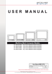
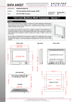
1
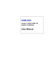
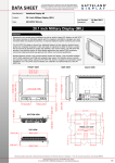
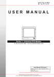
User Manual
JH 12T01 MMC - Maritime Multi Computer
Jakob Hatteland Display AS
Åmsosen, N-5578 Nedre Vats, Norway
Phone: +47 5276 3700, Fax: +47 5276 5444
www.hatteland.com
User Manual JH 12T01 MMC
Updated: 17 Mar 2005
For models:
-A4
Doc Id: INB100011-1 (Rev 4)
Slim
User Manual
Copyright © 2005 Jakob Hatteland Display AS
Aamsosen
N-5578 Nedre Vats, Norway
Information in this manual are copyrighted to the respective owners. All rights are reserved by Jakob
Hatteland Display AS. This information may not, in whole or in part, be copied, photocopied, reproduced,
translated or reduced to any electronic medium or machine-readable form without the prior written consent
of Jakob Hatteland Display AS.
The products described, or referenced, herein are copyrighted to the respective owners.
The products may not be copied or duplicated in any way. This documentation contains proprietary
information that is not to be disclosed to persons outside the user’s company without prior written consent
of Jakob Hatteland Display AS.
The copyright notice appearing above is included to provide statutory protection in the event of
unauthorized or unintentional public disclosure.
All other product names or trademarks are properties of their respective owners !
Contents
Contents........................................................................................ 3
Contents of package
4
General .......................................................................................... 7
Introduction to Jakob Hatteland Display AS
About this manual
Basic Construction - Maritime Multi Computers
Product Labels (Example)
Serial Number Label
Warranty Label
Capacitive Touchscreen
Resistive Touchscreen
7
8
9
10
10
10
11
12
Installation Recommendations ................................................. 13
Installation and mounting of computers
Cables
Physical Overview - JH 12T01 MMC
Pin Assignments - Common Connectors
13
13
14
16
Specifications ............................................................................. 19
Specifications - JH 12T01 MMC
20
Technical Drawings.................................................................... 21
Technical Drawings - JH 12T01 MMC
Exploded View - JH 12T01 MMC
22
23
General - Appendix .................................................................... 25
Basic Trouble-shooting
Testing & Approvals Overview
Declaration of Conformity
Return Of Goods Information
Terms
Notes
General Notes: (For all products)
Note for ECDIS Systems
Note for Documentation CD-ROM
Revision History
26
27
29
30
31
34
34
34
34
35
Contact Information ................................................................... 36
3
IND100130-10
INB100011-1 (Rev 4)
Contents of package
This product is shipped with:
Item
Description
1 pcs of Windows Operating System CD(s) or alternative
operating system(s).
Illustration
Driver software CD(s) for factory installed components like
mainboard, IDE, network etc. For more information see
the Installation Recommendations chapter.
1 pcs of Standard Power Cable.
(European or US standard) - Length approx: 1.9m
Note: Power cable not included in the DC version.
1 pcs of User Manual (Slim version)
Note: The separate documentation for third party
components are available on attached CD. The printed
manual only covers specific information for Hatteland
products, and not third party components.
1 pcs of configuration, test report and checklist sheets.
Optional accessories for Panel Computers:
Item
Description
Bracket mounting kit: (Delivered only with optional bracket)
4 pcs of RenCol Tristar Knob Male - M6X10 mm
4 pcs of MicroPlastic - 6 mm Nylon washer.
4 pcs of Bolt with shoulder washer - M6X1X20
4 pcs of Flat washer
4
IND100207-1
Illustration
Suspension Bracket
INB100011-1 (Rev 4)
General
5
INB100011-1 (Rev 4)
6
Jakob Hatteland Display AS
KNOWLEDGE - QUALITY - ECONOMY
Introduction to Jakob Hatteland Display AS
Founded in 1987, Jakob Hatteland Display (JHD), based in Norway, offers the widest range of
type approved marine monitors, panel computers and type approved marine computers for the
worldwide commercial, naval, yacht and cruise market.
Today the group develops and manufactures a complete range of IEC 60945 tested marine
monitors, panel computers and IEC 60945 tested marine computers.
Approved Marine Displays (MMD/STD)
Hatteland Display’s marine monitors are based on high quality and state-of-the-art components
with the highest specifications, and meet all requirements for harsh maritime use. The displays
are easily integrated into your system, due to standardized products and features.
The MMD (Maritime Multi Display) series consists of sizes ranging from 10in to 23in.
Specifically designed for navigation and automation systems on ships, these certified LCD
monitors comply to IP66 described in IEC 60925, are tested according to IEC 60945 and are
approved by major classification societies such as ABS, BV, ClassNK, DNV, GL and LR.
Further to this marine standard, the 19in MMD, the 20in MMD and the 23in MMD
marine monitors are also available as ECDIS and ARPA radar-compliant units.
Approved Marine Panel Computers (MMC)
The combination of the reliable design of the marine TFT-LCD modules, together with industrial
computer boards, allows Hatteland Display to offer a product range for customer applications
where space is critical and full function is desired in a single unit. In particular, the standardized
ETX-board form factor allows full flexibility when it comes to processor choice. Because of
multiple useful standard components we can offer a highly attractive commercial package
The MMC (Maritime Multi Computer) series consist of sizes ranging from 10in to 23in.
These products have also been designed for typical marine applications in navigation,
automation and other systems. Following Hatteland’s philosophy, these marine panel computers
are fully tested according to IEC 60945 and are designed for type approval.
Approved stand-alone and rack-mounted marine computers
Two concepts are followed to offer variation in size, function and expansion slots for customers:
approved black-box computers for limited space and approved computers for standard
19in racks, which offer a high degree of expansion. Configurations according to customer
wishes are implicit, such as the operating system, CD-burner, RAM, graphic card, HD, add-on
cards, factory installed software and many, many more.
General
IND100077-1
7
INB100011-1 (Rev 4)
Jakob Hatteland Display AS
The approved computers are tested according to IEC 60945 and IACS E10 and meet the
requirements for IEC 61174 (ECDIS). Several approvals by major classification societies such as
ABS, BV, ClassNK, DNV, GL and LR are available or pending. The 19in rack computers can be
operated up to 70°C.
Flexible display solutions and night vision facilities
All the type-approved displays, panel computers and marine computers offer maximum flexibility
for customers’ applications. Hatteland Display offers all products with AC or DC power supply,
and marine displays and marine panel computers have a fully linear dimmable function for night
vision.
Upon the customer’s request, specific colour, mechanical or electrical function designs are
possible. Many more options are also available, including factory mounted touch screens, sun
visors for marine monitors, different Windows or Linux operating systems and brackets
Design and Production
All products are designed and controlled by Hatteland Display in Nedre Vats, Norway.
The production and configuration of all products is taking place within Hattelands production
plant#1 (opened in September 2003) in Nedre Vats, Norway. Here an extensive manufacturing
capacity is available for all products, and can be expanded in the future.
The chosen materials for the production of the products are specifically industrial components
and can fulfill form-fit-and-function requests.
About this manual
The manual contains electrical, mechanical and input/output signal specifications. All specifications
in this manual, due to manufacturing, new revisions and approvals, are subject to change without
notice. However, the last update and revision of this manual are shown both on the frontpage
and also in the “Revision History” chapter. Please use that as a reference.
Furthermore, for third party datasheet and user manuals, please see dedicated interactive CD
delivered with the product or contact our sales personnel for support.
General
IND100077-1
8
INB100011-1 (Rev 4)
Basic Construction - Maritime Multi Computers
Basic Construction
Maritime Multi Computers
Firewall & component mounting platform
Glass (or touchscreen option)
Backcover/chassis
TFT Display
Front frame
Front frame controller hatche
Illustration
General
IND100077-19
9
INB100011-1 (Rev 4)
Product Labels (Example)
Serial Number Label
Manufacturer & Country
Product & Serial Number
Product Information
Manufacture:
Jakob Hatteland Display
NORWAY
Description
Power rating
100W
Product:
19 Inch
TFT
Product type: #
JH 19T01MMD-A1-831
Serial Number
115VAC/60Hz
230VAC/50Hz
Input Voltage
Product Type and Serial Number
JH XXAXX AAA-AX-XXX
JH 19T01 MMD-A1-831
NOMENCLATURE
Example
Serial Number
Sub Version (AC-Odd / DC-Even number)
Version (Number & Product Name)
TFT (Thin Film Transistor)
Display Size (inch)
Jakob Hatteland (manufacturer)
Warranty Label
If you are to perform service on a unit still under warranty, any warranty will
be void if this label is damaged or removed. This label is usually located on the
back of the product and near the serial number label. This is to help our service
department to better determine if there has been any unauthorized service on a
product still under warranty.
General
IND100077-23
10
INB100011-1 (Rev 4)
Capacitive Touchscreen
Introduction to Jakob Hatteland Display products with touchscreen
JHD uses both Resistive and Capacitive touchscreen solutions for their products. Please visit our
website to verify what product and touchscreen solution your product have.
Capacitive Touchscreen
Capacitive touchscreens operate using oscillator circuits
that are located in each corner of the glass overlay and
measure the capacitance of the area to be “touched”.
Depending on where the user touches the overlay, the
oscillators will vary in frequency. A touchscreen controller
then measures the frequency variations to ascertain the
coordinates of the person’s touch. This glass overlay has
a coating that stores the charge deposited over its surface
electrically. It will not operate with either a gloved hand
or with a mechanical stylus.
Brief Specifications
Subject
Construction
Positional Accurancy
Touch Contact
Requirements
Enduarance Tested
Cleaning
Liquid Resistance
Light Transmission
Details
Top: ClearTek protective overcoat protects the sensors and increase durability.
Inside: Electrode X/Y grid pattern and conductive coating.
Bottom: Glass and conductive coating.
Small amount of voltage is applied to the four corners for measuring X and Y
coordinates of the touch point.
Reported touch coordinates are within 1.0% of true position.
(Based on viewing area dimensions)
3 ms for finger input.
More than 225 million touches in one location without noticable degradation to
the surface.
Water, isopropyl, alcohol, and similar non-abrasive cleaners.
Liquids on screen does not impede touchscreen performance.
Up to 88% at 550 nm; dependant on specific surface finish chosen.
Updated touchscreen drivers and documentation for your operating system:
Please visit our website www.hatteland.com for 3rd party software, drivers and complete
documentation for touchscreens. In case of problems, please contact our sales department.
Touchscreen
IND100110-1
11
INB100011-1 (Rev 4)
Resistive Touchscreen
Resistive Touchscreen
It generally uses a display overlay composed of layers,
each with a conductive coating on the interior surface.
Special separator “dots” are distributed evenly across the
active area and separate the conductive interior layers.
The pressure from using either a mechanical stylus or
finger produces an internal electrical contact at the
“action point” which supplies the controller with vertical
and horizontal analog voltages for data input. The resistive
touchscreens are anti-glare to reduce reflective shine
intensity, which will slightly diffuse the light output
throughout the screen. Resistive technology activation can
be initiated by; a gloved hand, fingernail, mechanical stylus
or an ungloved finger.
Brief Specifications
Subject
Construction
Details
Top: Polyester with outside hard-surface coating with clear or anti-glare finish.
Inside: Transparent conductive coating.
Bottom: Glass substrate with uniform conductive coating.
Top and bottom layers separated by separator dots.
Positional Accurancy
Standard deviation of error is less than +- 0.080-inch (2mm).
Touch Activation Force Typically 57 to 133 g
Expected Life
More than 35 million touches in one location without failure, using a stylus similar
Performance
to a finger.
Chemical Resistance
Acetone, Ammonia-based glass cleaners, Common food and beverages,
(Exposed for one hour) Hexane, Isopropyl alcohol, Methylene chloride, Methyl ethyl ketone,
Mineral spirits, Turpentine
Light Transmission
Typically 75% over visible light spectrum.
Updated touchscreen drivers and documentation for your operating system:
Please visit our website www.hatteland.com for 3rd party software, drivers and complete
documentation for touchscreens. In case of problems, please contact our sales department.
Touchscreen
IND100110-1
12
INB100011-1 (Rev 4)
Installation Recommendations
Installation and mounting of computers
1. Most of our units are intended for various methods of installation or mounting
(rack mounting, panel mounting, bracket mounting, ceiling/wall mounting)
2. Adequate ventilation is a necessary prerequisite for the life of the unit. The air inlet and outlet
openings must definitely be kept clear; coverings which restrict ventilation are not permissible.
3. Exposure to direct sunlight can cause a considerable increase in the temperature of the unit, and
might under certain circumstances lead to overtemperature. This point should already be taken
into consideration when the bridge equipment is being planned (sun shades, distance from the
windows, ventilation, etc.)
4. Space necessary for ventilation, for cable inlets, for the operating procedures and for
maintenance, must be provided.
5. To further improve the cooling of the unit we recommend installing Cooling Fans underneath
blowing upwards into the unit air inlet. This may be required in high temperature applications
and also when there is reason to expect temperature problems due to non-optimal way of
mounting (Ref.2-5).
General mounting instructions
- The useful life of the components of all Electronics Units generally decreases with increasing
ambient temperature; it is therefore advisable to install such units in air-conditioned rooms. If there
are no such facilities, these rooms must at least be dry, adequately ventilated and kept at a
suitable temperature in order to prevent the formation of condensation inside the unit.
- With most Electronic Units, cooling takes place via the surface of the casing. The cooling must not
be impaired by partial covering of the unit or by installation of the unit in a confined cabinet.
- In the area of the wheel house, the distance of each electronics unit from the magnetic standard
compass or the magnetic steering compass must not be less than the permitted magnetic
protection distance. This distance is measured from the centre of the magnetic system of the
compass to the nearest point on the corresponding unit concerned.
- Transportation damage, even if apparently insignificant at first glance, must immediately be
examined and be reported to the freight carrier. The moment of setting-to-work of the equipment
is too late, not only for reporting the damage but also for the supply of replacements.
Cables
Use only high quality shielded signal cables. For RGB/DVI cables use only cables with separate
coax for Red, Green and Blue. We can supply a varity of high quality RGB/DVI, RS232,
PARALLEL, LAN and USB cables intended for this use.
Installation
IND100210-1
13
INB100011-1 (Rev 4)
Physical Overview - JH 12T01 MMC
Front area of computer
PS/2 Keyboard+Mouse
Power Button & LED
Buzzer
Brightness
PS/2 Keyboard+Mouse INPUT: (Applies also for rear mounted PS/2)
Connect the PS/2 cable to the PS/2 5P Connector (female) on the front side of the panel computer.
Three possible connections are available: Keyboard Only, Mouse Only (via designated PS/2 splitter), or
combined Mouse & Keyboard (via designated PS/2 splitter)
Power Button & LED:
To turn ON the computer, press down this button and release it immediately. The power indication (LED)
will turn green. If the computer is in standby this LED will be red.
To turn OFF the computer, press down this button and hold it for 3 seconds.
- Note: The operating system may require additionally tasks to be performed before computer shuts down.
Buzzer:
Sound indication from the internal speaker. Will sound a beep upon alarms or notifications from the
Operating System or other software that support System Speaker.
Brightness:
The product features a 100% dimmable image, which means it is capable of displaying a completely black
image when the brightness knob is turned fully to the left.
- Note: If the display is delivered with Transflective Technology, the dimming may vary depending on
environment. Transflective Technology uses environment / ambient lighting to preserve / enhance
the brightness, meaning such products are very suitable for viewing in direct sunlight.
14
IND100133-9
INB100011-1 (Rev 4)
Physical Overview - JH 12T01 MMC
Connector area of computer
Power Input
USB 0,1
Network COM1 RGB OUT
CompactFlash Reader
PS/2 Mouse+Keyboard (Same as in front)
Power INPUT: (AC or DC Model)
AC MODEL ONLY: The internal AC power module supports both 115VAC/60Hz and 230/50Hz power input.
DC MODEL ONLY: Secure the cables (check polarity!) to the screw terminal. The internal DC power
module supports voltage from 12 to 24 VDC.
USB INPUT/OUTPUT:
Connect any USB 1.1 compliant peripherals into either of these two USB connectors. Drivers for most USB
devices are useally included in operating system or on separate installation CD’s delivered with product.
USB 2.0 devices will operate in USB 1.1 mode (12 Mbps)
CompactFlash Reader:
CompactFlash Reader supports Type I & II cards. Insert the card gently into the slot with the logo facing
towards the TFT display). The drive letter assigned within the operating system will be automatically
unassigned when the card is removed from the slot. The card is removed by pulling the factory mounted
sticker extension away from the slot. This card & sticker is factory installed upon customer request.
Network INPUT/OUTPUT:
Supports 10/100Mbps Ethernet. Suitable for twisted pair cables CAT.5E. Make sure the network cable
connector ”clicks” into the RJ-45 connector.
COM1 Serial Port INPUT/OUTPUT:
Supports RS232/RS422/RS485 using a D-SUB 9P Male connector. Fasten the cable to the connector using
the provided screws on the cable housing itself.
RGB OUTPUT:
Will output a clone signal from the computer for use with external display or monitor. Connects via a
High Density D-SUB 15P Female connector. Fasten the cable to the connector using the provided screws
on the cable housing itself.
15
IND100133-9
INB100011-1 (Rev 4)
Pin Assignments - Common Connectors
Note: Not all connectors may be available on your specific product. This depends on the amount of additional
hardware installed from factory, or customized solutions. These pin assignments are for the common connectors used.
Pin Assignments - RJ45 10/100 LAN
Pin Assignments - RJ45 10/100/1000 GBLAN
1 2 3 4 5 6 7 8
1 2 3 4 5 6 7 8
Pin 01 - TDP
Pin 02 - TDN
Pin 03 - RDP
Pin 04 - NC
Pin 05 - NC
Pin 06 - RDN
Pin 07 - NC
Pin 08 - NC
Transmit Differential Pair (Positive)
Transmit Differential Pair (Negative)
Receive Differential Pair (Positive)
Not Connected
Not Connected
Receive Differential Pair (Negative)
Not Connected
Not Connected
Pin 01 - D0P
Pin 02 - D0N
Pin 03 - D1P
Pin 04 - D2P
Pin 05 - D2N
Pin 06 - D1N
Pin 07 - D3P
Pin 08 - D3N
Differential Pair 0 (Positive)
Differential Pair 0 (Negative)
Differential Pair 1 (Positive)
Differential Pair 2 (Positive)
Differential Pair 2 (Negative)
Differential Pair 1 (Negative)
Differential Pair 3 (Positive)
Differential Pair 3 (Negative)
Use category 5 - twisted pair cable
Pin Assignments - 9P Serial COM RS232
5
Pin Assignments - 15P HD RGB VGA
5 4 3 2 1
10 9 8 7 6
4 3 2 1
9 8 7 6
Pin 01 - DCD
Pin 02 - SIN
Pin 03 - SOUT
Pin 04 - DTR
Pin 05 - GND
Pin 06 - DSR
Pin 07 - RTS
Pin 08 - CTS
Pin 09 - RI
Data Carry Detect
Serial In or Receive Data
Serial Out or Transmit Data
Data Terminal Ready
Ground
Data Set Ready
Request To Send
Clear To Send
Ring Indicate
Pin 01
Pin 02
Pin 03
Pin 04
Pin 05
Pin 06
Pin 07
Pin 08
Pin 09
Pin 10
Pin 11
Pin 12
Pin 13
Pin 14
Pin 15
Pin Assignments - USB
Pin 2: Negative Data
Pin 4: Ground
15 14 13 12 11
Red, analog
Green, analog
Blue, analog
Reserved for monitor ID bit 2 (grounded)
Digital ground
Analog ground red
Analog ground green
Analog ground blue
+5V power supply for DDC (optional)
Digital ground
Reserved for monitor ID bit 0 (grounded)
DDC serial data
Horizontal sync or composite sync, input
Vertical sync, input
DDC serial clock
Pin Assignments - 5P PS/2 MOUSE
Pin 1: VCC +5V
Pin 3: Positive Data
Pin 6: Not Connected
Pin Assignments - 5P PS/2 KEYBOARD
Pin 6: Not Connected
Pin 4: Vcc +5V
Pin 3: Ground
Pin 5: Keyboard Clock
Pin 2: Not Connected
Pin 4: Vcc +5V
Pin 5: Mouse Clock
Pin 1: Mouse Data
Pin 3: Ground
Pin Ass. - 5P PS/2 KEYBOARD+MOUSE Combined
Pin 2: Not Connected
Pin 1: Keyboard Data
Pin 6: Mouse Clock
Pin 4: Vcc +5V
Pin 2: Mouse Data
16
IND100241-2
Pin 5: Keyboard Clock
Pin 3: Ground
Pin 1: Keyboard Data
INB100011-1 (Rev 4)
Pin Assignments - Common Connectors
Pin Assignments - 25P Parallel
13 12 11 10 9 8 7 6 5 4 3 2 1
25 24 23 22 21 20 19 18 17 16 15 14
Pin 01 - STROBE
Pin 02 - DATA0
Pin 03 - DATA1
Pin 04 - DATA2
Pin 05 - DATA3
Pin 06 - DATA4
Pin 07 - DATA5
Pin 08 - DATA6
Pin 09 - DATA7
Pin 10 - ACK
Pin 11 - BUSY
Pin 12 - PE
Pin 13 - SELECT
Pin 14 - AUTO FEED
Pin 15 - ERR#
Pin 16 - INIT#
Pin 17 - SLIN#
Pin 18 - GND
Pin 19 - GND
Pin 20 - GND
Pin 21 - GND
Pin 22 - GND
Pin 23 - GND
Pin 24 - GND
Pin 25 - GND
This signal indicates to the printer that data at PD7..0 are valid.
Parallel data bus from PC board to printer. The data line are able to operate in PS/2 compatible bi-directional mode.
Same as Pin 02
Same as Pin 02
Same as Pin 02
Same as Pin 02
Same as Pin 02
Same as Pin 02
Same as Pin 02
Signal from printer indicating that the printer has received the data and is ready to accept further data.
Signal from printer indicating that the printer cannot accept further data.
Signal from printer indicating that the printer is out of paper.
Signal from printer to indicate that the printer is selected.
This active low output causes the printer to add a line feed after each line printed.
Signal from printer indicating that an error has been detected.
This active low output initialises (resets) the printer.
Signal to select the printer sent from CPU board to printer.
Ground
Ground
Ground
Ground
Ground
Ground
Ground
Ground
Pin Assignments - 24P DVI-D
1 2 3 4 5 6 7 8
9 10 11 12 13 14 15 16
17 18 19 20 21 22 23 24
Pin 01
Pin 02
Pin 03
Pin 04
Pin 05
Pin 06
Pin 07
Pin 08
Pin 09
Pin 10
Pin 11
Pin 12
Pin 13
Pin 14
Pin 15
Pin 16
Pin 17
Pin 18
Pin 19
Pin 20
Pin 21
Pin 22
Pin 23
Pin 24
T.M.D.S. Data2 T.M.D.S. Data2 +
T.M.D.S. Data2/4 Shield
T.M.D.S. Data4 T.M.D.S. Data4 +
DDC Clock
DDC Data
Not Connected
T.M.D.S. Data1 T.M.D.S. Data1 +
T.M.D.S. Data1/3 Shield
T.M.D.S. Data3 T.M.D.S. Data3 +
+5V Power
Ground (for +5V)
Hot Plug Detect
T.M.D.S. Data0 T.M.D.S. Data0 +
T.M.D.S. Data0/5 Shield
T.M.D.S. Data5 T.M.D.S. Data5 +
T.M.D.S. Clock Shield
T.M.D.S. Clock +
T.M.D.S. Clock -
DDC = Display Data Channel
T.M.D.S = Transition Minimized Differential Signal
17
IND100241-2
INB100011-1 (Rev 4)
18
INB100011-1 (Rev 4)
Specifications
19
INB100011-1 (Rev 4)
Specifications - JH 12T01 MMC
Note: All specifications are subject to change without prior notice!
TECHNICAL DESCRIPTION
MECHANICAL DESCRIPTION
TFT Technology:
Physical Dimensions:
• 12.1 inch viewable image size
• Thin Film Transistor (TFT)
• a-Si TFT Active Matrix
• 320 (W) 288 (H) 62 (D)
• Weight: 4.4kg
User Controls:
TFT Characteristics:
•
•
•
•
•
•
•
•
•
Pixel number
Pixel pitch (RGB)
Response Time
Contrast Ratio
Light Intensity
Active Display Area
Max Colors
Viewable Angles
Resolutions
:
:
:
:
:
:
:
:
:
800 x 600
0.3075 (H) x 0.3075 (V) mm
25 ms (typical), “black” to “white”
600:1 (typ)
400 cd/m2 (typical)
246.0 (H) x 184.5 (V) mm
262,144 colors
Up: 45°, Down: 55°, Right: 70°, Left: 70°
800 x 600
Computer Specifications:
•
•
•
•
•
•
Processor
Cache / PCI Clock
System Chipset
BIOS
Memory
Graphics Chipset
• IDE Controller
• IDE HDD
:
:
:
:
:
:
:
:
•
•
•
•
Compact Flash
Serial Port
Ethernet
USB
:
:
:
:
•
•
•
•
Keyboard
Mouse
Speaker
Alarm
:
:
:
:
National Geode GX1 300Mhz with MMX
16KB Cache Level 1 / 33 MHz BUS
National CS5530A
Phoenix + Kontron Technology
1 x 128 MB (MAX 256MB) PC133 SDRAM
XPRESS Graphics
National CS5530A with 4MB RAM
2 x IDE Ports, Ultra DMA33
Fujitsu Automotive 20 GB internal,
2.5" IDE, 5400 RPM
1 x CF Socket (Type I & II)
1 x RS232/RS422/RS485 (NS16550 UART)
1 x 10/100 Mbps (Realtek 8139C)
2 x USB (USB 1.1 compliant, 12 MBit)
(USB Legacy not supported)
1 x PS/2
1 x PS/2
Build in speaker
Build in Buzzer (controlled by parallel port)
On front bezel:
• Power On/Off (push button with internal LED)
• Brightness Knob Wheel
Environmental Considerations:
• Operating
• Storage
: Temperature -15 deg. C to +70 deg. C
: (+70 deg. C non functional)
Humidity 30% to 90% (non condensing)
: Temperature -20 deg. C to +70 deg. C
Humidity 10% to 90% (non condensing)
Safety Considerations:
Even although the test conditions for bridge units provide for a maximum
operating temperature of 55°C, continuous operation of all electronic
components should, if possible, take place at ambient temperatures of only
25°C. This is a necessary prerequisite for long life and low service costs.
Input/Output Connectors:
Function
10/10 BaseT
Keyboard
Mouse
COM 1
COM 2
USB
DC Power
RGB OUT
Back side
1 x RJ-45
1 x PS/2
1 x DB9M
Inside
Front
1 x PS/2
Reserved for touchscreen
2 x Std USB 1.1
DC Screw terminal
1 x HDDB15F
Available Mechanical Options:
Accessories:
• Touch Screen **
* Option: Standard or custom logo and color
** Option: Factory mounted
Power Specifications:
Power Supply Options:
• 24 VDC
: Model JH 12T01 MMC A4*
*Tested according to EN60945 and IACS E10
Power Consumption:
• Operating
: 31W (Typ)
www.hatteland.com
20
INB100011-1 (Rev 4)
IND100129-41
Technical Drawings
21
INB100011-1 (Rev 4)
G
F
E
D
C
Measurements shown in cm
H
288
TOP VIEW
290
INB100011-1 (Rev 4)
2
3
4
4
This document is the property of Jakob Hatteland Display AS.
This document and any authorized reproduction thereof, must not be used in
any way against the interest of Jakob Hatteland Display AS.
Any authorized reproduction, in whole or in part, must include this legend.
1
JH 12T01 MMC-A2
15
Spectrum Control
52-160-002A
Filtered Terminal Block
BOTTOM VIEW
320
FRONT VIEW
3
5
5
254
6
SIDE VIEW
6
ISOMETRIC VIEW
19
B
2
7
7
8
8
14
128
6
14
6
9
9
294
4701
Mechanical DesignerProjection:
10
Jakob Hatteland Display
Åmsosen
N-5578 Nedre Vats
18-09-2003
Date:
PANEL CUT OUT
11
1:1.5
Size: A1 Format
Scale:
Holes Ø 5,50
screwed from the backside of panel
4 places
145
M5
4 places
11
VESA MOUNTING
BACK VIEW
10
75
A
1
--
14
Revision:
1
12
Based On A000433-1
Drawing number:
Approved by:
14
12
6
258
IND100132-61
19
62
22
6
Due to dimensions without decimals, the tolerance on drawings is +/- 1mm (For accurate measurements, measure in AutoCAD)
Technical drawings (.DWG format) are found on our internet site: http://www.hatteland.com
H
G
F
E
D
C
B
A
Technical Drawings - JH 12T01 MMC
23
IND100132-61
INB100011-1 (Rev 4)
Front
This document is the property of Jakob Hatteland Display AS.
This document and any authorized reproduction thereof, must not be used in
any way against the interest of Jakob Hatteland Display AS.
Any authorized reproduction, in whole or in part, must include this legend.
LCD
Touch
Power
Single Board Computer
Harddrive
Chassis
Exploded View - JH 12T01 MMC
24
INB100011-1 (Rev 4)
General - Appendix
25
INB100011-1 (Rev 4)
Basic Trouble-shooting
COMMON ERRORS: (Applies for Display products and Panel / Maritime / Rack Computers)
If for some reason there should be something wrong with the picture quality or no picture present,
check the symptoms carefully and try to cure it with the hints below:
NO PICTURE / LED BEHAVIOUR:
If there is no light at all in the LED at the FRONT, check power cables. If the LED in front is green
then check if the brightness knob is turned to the right (max brightness). If still no picture, check
if there is a VGA signal on the External VGA connector. If you have a picture on the external VGA
connector please look in BIOS documentation/chapter for correct display settings in BIOS.
Lack of image is most likely to be caused by incorrect connection, lack of power, or wrong BIOS
settings.
SCROLLING / UNSTABLE IMAGE:
Signal cable may not be completely connected to computer or TFT display.
Check the pin assignments and signal timings of the display and your video card with respect to
recommended timing and pin assignments. Make sure that the video card is compatible and that it
is properly seated / installed on the computer.
DISPLAY AREA IS NOT CENTERED / SIZED CORRECTLY
Make sure that a supported video mode has been selected on the display, or on the
video card / system. If it is impossible to position the image correctly, ie the image adjustment
controls will not move the image far enough, then test it again using another graphics card for the
PC system. This situation can occur with a custom graphics card that is not close to standard
timings or if something is in the graphics line that may be affecting the signal, such as a signal
splitter (please note that normally a signal splitter will not have any adverse effect).
If it is impossible to change to the correct resolution/color depth, check if you have the right VGA
driver installed in your system.
IMAGE APPEARANCE:
A faulty TFT panel can have black lines, pixel errors, failed sections, flickering or flashing image.
Incorrect graphics card refresh rate, resolution or interlaced mode will probably cause the image
to be the wrong size, it may scroll, flicker badly or possibly even no image is present. Sparkling on
the display may be a faulty TFT panel signal cable.
CONTINUED FAILURE:
If unit after unit keeps failing, consider and investigate whether you are short circuiting the
equipment or doing something else seriously wrong.
DEW CONDENSATION BEHIND GLASS:
Power on the TFT product and set brightness to 100%. Turn off any automatic screensavers on
PC or similar. During minutes the dew will be gone. To speed up the process, use a fan heater for
a reasonable time. Do not overheat the TFT product.
General - Appendix
IND100077-8
26
INB100011-1 (Rev 4)
Testing & Approvals Overview
These products have been tested / type approved by the following classification societies:
Type Number
Tests
Certificated by
JH 10T06 STD Ax
EN60529 (IP66) (Applies only for flush mounting)
JH 10T06 MMD Ax
EN60945 3rd (IEC945 3rd)
EN60529 (IP66) (Applies only for flush mounting)
ClassNK - Nippon Kaiji Kyokai
DNV - Det Norske Veritas
GL - Germanischer Lloyd
BV - Bureau Veritas
JH 17T01 MMD Ax
EN60945 3rd (IEC945 3rd)
EN60529 (IP66) (Applies only for flush mounting)
ClassNK - Nippon Kaiji Kyokai
ABS - American Bureau of Shipping
DNV - Det Norske Veritas
LRS - Lloyd's Register of Shipping
GL - Germanischer Lloyd
BV - Bureau Veritas
JH 19T02 MMD Ax
EN60945 4th (IEC945 4th)
JH 20T03 MMD Ax
EN60945 3rd (IEC945 3rd)
EN60529 (IP66) (Applies only for flush mounting)
EN61174 (IEC1174) - Bundesamt für Seeschiffahrt und Hydrographie (BSH)
ClassNK - Nippon Kaiji Kyokai
ABS - American Bureau of Shipping
DNV - Det Norske Veritas
LRS - Lloyd's Register of Shipping
GL - Germanischer Lloyd
BV - Bureau Veritas
JH 15T05 STD Ax
JH 15T05 MMD Ax
JH 20T05 MMD Ax
JH 23T02 MMD Ax
General - Appendix
IND100077-10
27
INB100011-1 (Rev 4)
Testing & Approvals Overview
These products have been tested / type approved by the following classification societies:
Type Number
Tests
Certificated by
JH 12T01 MMC A4
EN60945 4th (IEC945 4th)
IACS E10
DNV - Det Norske Veritas
ClassNK - Nippon Kaiji Kyokai
GL - Germanischer Lloyd
BV - Bureau Veritas
JH 15T05 MMC A1
EN60945 4th (IEC945 4th)
IACS E10
ClassNK - Nippon Kaiji Kyokai
GL - Germanischer Lloyd
DNV - Det Norske Veritas
JH 19T02 MMC A1
EN60945 4th (IEC945 4th)
IACS E10
ClassNK - Nippon Kaiji Kyokai
GL - Germanischer Lloyd
DNV - Det Norske Veritas
JH 23T02 MMC A1
EN60945 4th (IEC945 4th) (Pending)
IACS E10 (Pending)
General - Appendix
IND100077-10
28
INB100011-1 (Rev 4)
Declaration of Conformity
We, manufacturer
Jakob Hatteland Display A/S
Åmsosen, N-5578 Nedre Vats, Norway
declare under our sole responsibility that the
MMD, MMC, STD and MIL products
is in conformity with the following standards
in accordance with the EMC Directive
EN 55022 Class A - Emission
EN 55024 - Immunity
Signature:........................................................
Frode Grindheim
Technical Director
Jakob Hatteland Display A/S
Signature:........................................................
Arne Kristiansen
Development Engineer
Jakob Hatteland Technology A/S
Date: 08 September 2004
Return Of Goods Information
Return of goods: (Applies not to warrenty/normal service/repair of products)
Before returning goods, please contact your system supplier before sending anything directly
to JHD. When you return products after loan, test, evaulation or products subject for credit,
you must ensure that all accessories received from our warehouse is returned to JHD.
This applies to cables, powermodules and additional equipment except screws or similar, user
manual, datasheets or other written paper documents. Furthermore, the product must not have any
minor / medium or severe scratches, chemical spills or similar on the backcover, front frame or
glass.
This is needed to credit the invoice 100%. Missing parts will not be subject for credit, and you will
not get total credit for returned product. You will either be charged separately or the amount is
withdrawn from the credit. If you noticed that our product missed accessories upon receival, we
are of course open for further investigation and positive solutions. If you decide to ship the missing
items on the after hand, you will get 100% credit for that particular invoice or items received at JHD
incoming goods control. Please contact our sales personnel if additional questions.
Current prices apply as per May 2004:
Signal Cable DSUB 15P Male or Female - Approx 1,8meters
Price:
170,- NOK each
Signal Cable BNC 5P - Approx 1,8meters
Price:
350,- NOK each
RS-232 serial cable DSUB 9P - Approx 1,8meters
Price:
80,- NOK each
Powercable 110 / 220 VAC (European or US standard) - Approx 1,8meters
Price:
50,- NOK each
Minor / Medium or severe scratches / chemical spill on backcover
Price: 1300,- NOK
Any scratch, chemical spill or similar on front frame (including glass)
(Prices are approx, and any deviation are evaulated during incoming goods control)
Price: 2000,- NOK
Approved packaging methods/materials: (Applies to all shipments to JHD)
When returning goods, please make sure you surround the product with the following material,
whenever possible: Original packaging from JHD, firm foam material, bubble wrap or lots of
PadPack paper or Foam chips/polyester wrapped in sealed plastic bags. In any case, always use a
solid cardboard box to surround everything.
Not approved packaging methods/materials are: Foam chips, expanded polyester, clothes, nothing,
or too little, or anything that will crumble and get into the ventilation holes of products and
cardboard boxes that are not suitable to secure the product during shipment.
General - Appendix
IND100077-14
30
INB100011-1 (Rev 4)
Terms
The Hatteland Group - Terms Of Sale And Delivery:
1) APPLICATION
The terms of sale and delivery include the following companies: Autostore AS, Jakob Hatteland Assembly AS,
Jakob Hatteland Computer AS, Jakob Hatteland Display AS, Jakob Hatteland Logistics, Jakob Hatteland Supply AS
and Jakob Hatteland Technology AS.
2) PRICE
a) The price is per each, if nothing else has been stated, VAT not included. Price is based on the prices from our
suppliers, current custom rates, taxes, rate of exchange and international raw material prices. We reserve ourselves
the rights to adjustments in case of alternation on the above mentioned.
b) Included in the price is the supplier’s standard packing. In case of re-packing/smaller quantities we reserve
ourselves the right to add an additional sum for warrantable packing according to CECC 0015 (Basic inspection for
protection of electrostatic sensitive devices)
3) VALIDITY
If nothing else has been stated in our quotation, the offer is valid for 30 days from the date of quotation.
4) PACKAGE QUOTATION
A package quotation means that all the components offered, must be ordered by us. If one component or more are
removed from the quotation, the prices given in the package quotation are not valid.
5) TERMS OF PAYMENT
Cash on delivery or payment in advance. Net granted for companies, schools and institutions only, according to
agreement. In case of too late payment 1.5% interest/month will be charged. Seller has mortage rights in the goods
delivered until the purchase price, additional interests and charges have been paid in full. Accepted bill is not
considered as payment until it has been honoured in full.
6) TIME OF DELIVERY
The quoted time of delivery is based on information from our suppliers. We disclaim any responsibility for the
consequences of any delay or cancellation from our suppliers. Belated delivery gives not solely the right for
cancellation.
7) DELIVERY POINT OF TIME
Goods are considered delivered to customer when handed over to charterer.
8) FREIGHT / PACKING / FORWARDING FEE
Jakob Hatteland Display AS charge NOK 50 in forwarding fee for orders below NOK 1.000. For orders below
NOK 1.000 Jakob Hatteland Supply AS charge freight according to expenses, and NOK 25 for packing. For handling
requested beyond ordinary hours NOK 250 is charged. Express service is charged with NOK 100 + freight charges.
All the companies charge freight according to expenses for orders above NOK 1.000. VAT not included.
9) COMPLAINT
By receipt customer must check goods for obvious defects which have to be claimed within 8 days from receipt.
Otherwise acceptance of complaint can not be counted on.
10) GUARANTEE / SERVICES
Time of guarantee is calculated from our date of shipment, and applies to the extent that we are covered by our
supplier’s guarantee regulations. The guarantee does no longer apply if:
I) there has been encroached upon the goods without seller’s consent
II) terms of payment is not fulfilled
III) the goods have been damaged due to unskilled treatment
IV) components which are sensitive for static electricity have not been unpacked and treated in a secure way.
Minimum requirements: CECC 00015’s standards for handling of such components. The guarantee does not include
fair wear and tear.
General - Appendix
IND100077-7
31
INB100011-1 (Rev 4)
Terms
11) RESPONSIBLITY
Seller undertake to deliver faultless and functional capable goods according to existing technical specifications.
Seller disclaim responsibility for any damage or loss which directly or indirectly may be caused due to failure or defect
with the delivered goods, if carelessness from the seller can be limited up to the cost of the goods. The supplier’s
responsibility for defects with the supplied goods do not include secondary damage or loss.
12) CANCELLATION / RETURN
Binding sales contract is concluded when we have confirmed customer’s purchase order. Any disagreements in our
order confirmation must be reported to seller within 6 days. The agreement can not be altered without our permission,
after acceptance from our supplier. If goods are wanted to be returned, a Return No must be assigned from seller.
Returned goods without a Return No will not be accepted. By return of stock listed goods, 20% return fee is charged.
Returned goods are shipped on customer’s account and risk.
13) LOAN, RENT and DEMO
When borrowing of goods for demo/test, the date of return must be added to the document. If no date has been
stated, date of return is two weeks from the date of the document. Before return, seller must be contacted for a
Return No (RTK). Goods which have been sold with an agreed right of return within stated terms, shall also have a
Return No. The Return No must be obtained before the stated date of return. Returned goods without a Return No, or
which have not been packed in original packing, will not be accepted.
14) LIMITATIONS
If any of our suppliers claim limited delivery terms towards us, our terms of delivery will be restriced according to
those.
15) SOFTWARE
Sold or borrowed software is not allowed to be copied or spread in other ways, without a written permission.
16) RE-EXPORT
Goods delivered from seller may be subject to special rules of exportation in their supplier’s native country. Buyer is
responsible to obtain necessary permissions for further export/re-sale.
17) QUESTION IN DISPUTE
To settle any dispute the Karmsund Herredsrett is approved the legal venue.
General - Appendix
IND100077-7
32
INB100011-1 (Rev 4)
Terms
INSTRUCTIONS FOR THE CONSIGNEE
1) CONTROL
Control the goods immediately by receipt. Examine the quantity towards the invoice/packinglist/shipping documents.
Look for outward defects on the packing which may indicate damage on or loss of contents. Control the container and
the seals for any defects.
2) SECURING EVIDENCE
When defects on the goods have been found, evidence must be secured, and seller must be informed. Call the
transporter and point out the defects. Add a description of the defects on the goods receipt, the forwarder’s copy of
the way-bill or on the driving slip.
3) RESCUE
Bound the damage. Try to restrict the damage and the loss. Seller will compensate expences incurred due to
reasonable security efforts in addition to damage and loss.
4) COMPLAINT
Write immediately a complaint to the transporter or his agent. Forward immediately the complaint to the transporter or
his agent, and hold the transporter responsible for the defects. The complaint must be sent at the latest:
- for carriage by sea:
within 3 days
- for overland / air transportation
within 7 days
5) DOCUMENTATION
For any claims the following documentation is required, and must be forwared to the company or their agent:
invoice, way-bill and/or bill of landing, and/or statement of arrival, inspection document, besides a copy of the letter of
complaint to the transporter.
General - Appendix
IND100077-7
33
INB100011-1 (Rev 4)
Notes
General Notes: (For all products)
- The unit is type approved according to EN60945 4th, 4.4, equipment category b) protected
from the weather.
- Other type approvals applies for the different products.
Please see Testing & Approvals Overview section in this manual for more information.
- Use of brightness and push buttons may inhibit visibility of information at night.
Note for ECDIS Systems
For ECDIS systems the brightness knob indication mark should be aligned directly with the
indication mark located on the label. (See Physical Overview or Operation section in this manual)
Note for Documentation CD-ROM
The separate and full documentation for third party components (including options that are factory
installed) are available on attached CD. The printed physical manual only covers specific
information for Hatteland products, and not generally includes third party components.
General - Appendix
IND100077-20
34
INB100011-1 (Rev 4)
Revision History
Rev.
1
2
3
4
By
SE
SE
SE
SE
Date
28 May 04
03 Sep 04
10 Feb 05
17 Mar 05
Notes
First release.
General update.
Updated Testing & Type Approval section.
Updated Testing & Type Approval section.
General - Appendix
IND100077-22
35
INB100011-1 (Rev 4)
Contact Information
Main office, Vats / Norway:
Jakob Hatteland Display AS
Åmsosen
N-5578 Nedre Vats
Norway
Tel: +47 5276 3700
Fax: +47 5276 5444
Sales office, Oslo / Norway:
Jakob Hatteland Display AS
Gjerdrums vei 12
N-0484 Oslo
Norway
Tel: +47 5276 3700
Fax: +47 2258 6790
Sales office, Frankfurt / Germany:
Jakob Hatteland Display GmbH
Werner Heisenberg Strasse 12
D-63263 Neu-Isenburg
Germany
Tel: +49 6102 370 954
Fax: +49 6102 370 968
Sales office, Orlando / USA:
Jakob Hatteland Display Inc.
801 International Parkway, 5th Floor
Lake Mary, FL 32746
USA
Tel: +1 407 562 1677
Fax: +1 407 562 1777
www.hatteland.com
Thank you for choosing our quality products !