1
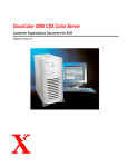
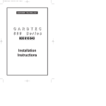
LIGHTFENCE SECURITY DEVICE FOR PERIMETER PROTECTION USER'S MANUAL LIGHTFENCE CONTROLER DIAGRAM How it works Azco LightFence detects distortions (attenuation) in the AzcoWire Cable caused by intrusion attempts, both by climbing over and by lifting the mesh. It is necessary to make sure that the cable AzcoWire is placed and fastened to the mesh properly in order for LightFence to detect bends of the mesh following to intrusion attempts. The installation instructions in this manual will enable you to satisfy the above mentioned conditions. It is necessary to read this manual before installing LightFence, as most of the problems that usually occur are due to installation mistakes. General Precautions AzcoWire Plastic Optical fiber is very robust, UV resistant and not easily breakable, but bends and angles may significantly reduce the maximum distance of the system. Do not walk or tread on AzcoWire: Do not exceed more than 25lbs tensile force when pulling AzcoWire: Minimum bend radius of 1” (25mm): LightFence Installation 1) Drill the fence posts with a 3/16” (5mm) head and use a de-burring tool to smooth the edges or with an 5/16” (8mm) head. Best to use Azco AZLFTB Tension Bolts to save time and will be less likely to damage AzcoWire LightFence Installation 2) Insert the fiber in the holes of the posts and through the mesh, in and out, every 40” (1m), at 20” (50cm)away from the posts. Tie the fiber to the mesh only once in the middle between the two posts, as shown in the figure beside: LightFence Installation 2a) Using with “Unarmed” gate . LightFence Installation 2b) Using with “Armed” swing gates. AzcoWire in conduit or track under gate area, loops on actual gate with some Slack at post so it can be opened. Keep in mind opening gate will trigger alarm. If it is guarded in this area with gate in use then just use conduit under fence for AzcoWire LightFence Installation 3) Insert the cables into the cable gland of the LightFence Controller IP66 rated Enclosure then terminate the connectors. Terminating AzcoWire 4) Cut the fiber with the cutting tool. 5) Remove the jacket Remove about 1 cm jacket. The jacket of the optical cable has a diameter of 2.2mm. The fiber has a diameter of 1 mm. ATTENTION! Use a standard cable stripper with a hole of 1.0 mm or more, so you will not damage the fiber. LightFence Installation 6) Connectorization a. Insert the protection boot over the AzcoWire. b. Insert the FSMA connector onto the cable till the jacket stops against the connector; the fiber should extend 2mm out of the connector. c. Crimp the FSMA connectors on the cable jacket. WARNING The connector must be crimped on the cable jacket and must not be crimped directly on the fiber. The crimp tool for FSMA connectors must have a hexagonal crimping diameter of 3mm. When using the AzcoWire crimp tool use the 0.122” hole. 7) Fiber polishing Polish/level the fiber by connecting the connector to the polishing puck, Place the puck on the polishing paper/ sand paper, then polish in a figure 8 motion until the fiber is flush with the puck. LightFence Installation 8) Connect the terminated AzcoWire to the LightFence controller. 9) Connect the alarm zone (D) from the alarm system; in case the LightFence devices are placed “in bus”, only the last device will be connected to the alarm system. The circuit is normally closed , so the relay is closed. In case of disconnection, cable break, no power or cable bending, the circuit opens. 10) Connect power supply (e.g.from the battery of the alarm system) Connect the power supply (A) (see previous figure). The yellow led glows for a few seconds and then the green led will glow. From this moment on, the transmission port(Tx) emits codified light signals which go across the AzcoWire plastic optical fiber and arrives at the receiving port (Rx). The device will continually control the power of the signal received. When the device detects a difference in power, due to cable cut or bending of the AzcoWire fiber, an alarm will go off. The alarm status is shown on the display and with the glowing red led. LightFence Installation 11) 4- Connect the alarm relay (10A to 240VAC) to the alarm system; you can place the anti-tampering sensor in-series. 12) This device has 4 sensitivity levels you can select according to your application using the selector (F). The intermediate levels can be used to decrease the system sensitivity in case, for example, of alarms due to bad weather conditions or to increase the protection level. After changing sensitivity, reset the system using the reset button(G). LightFence Installation When installing on a fence with no mid support beams. When installing on a fence with mid support beams. LightFence Installation Monitoring the data on light power variations LiteFence continually logs the attenuation rates over the cable as well as alarms, recording them in an SD memory card (E). Date and time are already set. After one month that the device has been operating, you can send the SD memory card to Azco: we will give you free support about the most appropriate level of sensitivity that should be selected on the device. For this reason, there are 2 SD memory cards in the package. WARNING: the files reporting the logs can only be read by a special software of the controller Do not try to open the SD memory card, as all data could be cancelled. LiteFence indicates when the maximum link length or the maximum attenuation rate has been reached with the following alert on the display. In this case, the system keeps operating correctly, but we recommend turning down sensitivity in order to avoid false alarms. Sensitivity can be adjusted using the selector (F), as shown on page 9. ATTENTION! LINK IS TOO LONG LightFence Installation Azco LightFence features a text interface which you can access using the button on the right of the display. Functions: Up - menu scroll upwards Down - menu scroll downwards OK - option selection ESC - menu exit The tree structure will be explained in the next section. Sub-menus: Firmware: shows current firmware version Language: language can be selected Clock: shows date/time, which can also be set Status: reports statistical data on how the device is working Settings: you can set the analysis time window of the light signal attenuation. The variation of this parameter detects attenuation variations in different intervals. Rates range from 1s(default: lowest sensitivity) to 60s (highest sensitivity). LightFence Installation