1
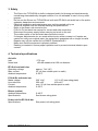
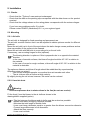
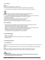
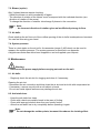
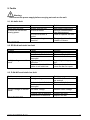
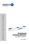
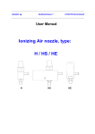
SIMCO (Nederland) B.V. Postbus 71 7240 AB Lochem, The Netherlands Telephone + 31-(0)573-288333 Fax + 31-(0)573-257319 E-mail [email protected] Internet http://www.simco-ion.nl Apeldoorn trade register no. 08046136 TYPHOON Ionizing air knife User manual Typhoon_UM_9752902012_GB_V2_1 USER MANUAL FOR TYPHOON CONTENTS Preface ...................................................................................................................................... 2 Explanation of symbols .............................................................................................................. 2 1. Introduction ............................................................................................................................ 3 2. Description and operation ...................................................................................................... 4 3. Safety ..................................................................................................................................... 5 4. Technical specifications ......................................................................................................... 5 5. Installation .............................................................................................................................. 6 5.1. Checks ............................................................................................................................ 6 5.2. Mounting.......................................................................................................................... 6 5.2.1. Air knife ..................................................................................................................... 6 5.2.2. Lines/air ducts ........................................................................................................... 6 5.2.3. Power unit for EP-Sh-N bar ...................................................................................... 7 5.3. Connecting the anti-static bar .......................................................................................... 7 5.3.1. EP-Sh-N anti-static bar ............................................................................................. 7 5.3.2. P-Sh-N-Ex anti-static bar .......................................................................................... 7 5.4. Blower (option) ................................................................................................................ 7 5.4.1. General ..................................................................................................................... 8 5.4.2. Installation................................................................................................................. 8 6. Commissioning ...................................................................................................................... 8 7. Functional check .................................................................................................................... 8 7.1. Anti-static bar .................................................................................................................. 8 7.2. Blower ............................................................................................................................. 9 7.3. Air knife ........................................................................................................................... 9 8. Maintenance .......................................................................................................................... 9 8.1. Air knife ........................................................................................................................... 9 8.2. Anti-static bars................................................................................................................. 9 8.3. Blower ........................................................................................................................... 10 8.3.1. Motor part ............................................................................................................... 10 8.3.2. Blower part.............................................................................................................. 10 8.3.3. Lubricants ............................................................................................................... 10 8.4. Filter .............................................................................................................................. 10 9. Faults ................................................................................................................................... 11 9.1. Air knife fault.................................................................................................................. 11 9.2. EP-Sh-N anti-static bar fault .......................................................................................... 11 9.3. P-Sh-N-Ex anti-static bar fault ....................................................................................... 11 9.4. Motor faults.................................................................................................................... 12 10. Repair ................................................................................................................................ 12 11. Disposal ............................................................................................................................. 12 12. Spare parts & accessories ................................................................................................. 12 Typhoon_UM_9752902012_GB_V2_1 1 Preface This manual describes the installation and usage of the TYPHOON air knife. This manual must be available at all times to staff operating the equipment. Read through the entire manual before installing and/or using the product. Follow the instructions set out in this manual to ensure proper operation of the product and to retain your entitlement under the guarantee. The terms of the guarantee are set out in the SIMCO (Nederland) B.V. General Terms and Conditions of Sale. Explanation of symbols Warning Indicates special information for preventing injury or significant damage to the product or the environment. Note Important information for efficient use and/or to prevent damage to the product or the environment. Typhoon_UM_9752902012_GB_V2_1 2 1. Introduction The Simco-Ion TYPHOON air knife is designed to clean and neutralise electrostatically charged surfaces using a powerful ionized air flow. Figure 1: Air knife with EP-Sh-N bar Ionising air out Figure 2: Air knife with P-Sh-N-Ex bar Ionising air out Typhoon_UM_9752902012_GB_V2_1 3 2. Description and operation The TYPHOON air knife neutralises static electricity and removes dirt from flat and curved surfaces using a powerful ionized air flow. This air flow is generated by a powerful blower (option) and an air knife. The air knife comes with a type EP-Sh-N anti-static bar (figure 1) as standard. If the air knife is to be used in explosion-hazardous zones, the P-Sh-N-Ex anti-static bar (figure 2) is required. The anti-static bar produces positive and negative ions which are blown onto the surface by the air knife. When this air flow is pointed at an electrostatically charged surface, electrons are exchanged and the surface is neutralised. This ensures that the material is neutralised as it is blown clean and prevents the particles that are blown off from being re-attracted. The selected blower should have enough capacity to the air flow corresponding to the selected level as indicated in the graph below. Level 1 Level 2 Level 3 Level 4 Level 5 Level 6 Level 7 10 - 20 mbar 20 - 50 mbar 50 - 100 mbar 100 - 150 mbar 150 - 200 mbar 200 - 250 mbar 250 - 300 mbar Static removal only Light dust removal / Long range static removal Dust removal Heavy dust removal Extra Heavy dust removal Special applications Special applications Typhoon air knife flow per meter (@ s td. s lot opening 0.5 mm ) 450 m³/h 400 m³/h 350 m³/h Air Knife Flow . 300 m³/h 250 m³/h 200 m³/h 150 m³/h 100 m³/h 50 m³/h 0 m³/h Flow 25 m bar 50 mbar 75 mbar 100 mbar 125 mbar 150 mbar 175 m bar 200 m bar 225 mbar 250 mbar 275 m bar 300 m bar 126 m³/h 176 m³/ h 213 m ³/ h 243 m ³/h 268 m³/h 291 m³/h 311 m ³/ h 329 m ³/h 345 m³/h 360 m³/h 374 m ³/ h 387 m ³/ h Air Knife Pressure Typhoon_UM_9752902012_GB_V2_1 4 3. Safety - The Simco-Ion TYPHOON air knife is designed solely for blowing and simultaneously neutralising electrostatically charged surfaces. It is not advisable to use it for any other purpose. Do not use the Simco-Ion TYPHOON air knife with EP-Sh-N anti-static bar in fire and/or explosion hazardous environments. Electrical installation and maintenance may only be carried out by an electrical engineer with the relevant training and qualifications. Refer to the power unit manual or the P-Sh-N- Ex anti-static bar manual for correct and safe connection. Disconnect the power supply before carrying out work on the unit. The emitter points of the anti-static bars are safe to touch. If changes, adjustments etc. are made without prior written consent or if repairs are carried out using non-original parts, the equipment's guarantee will no longer be valid. Repairs may only be carried out by SIMCO (Nederland) B.V. Make sure that the equipment is properly earthed. Earthing is needed to ensure proper operation and to prevent electrical shocks upon contact. 4. Technical specifications Air knife Inlet Noise level 75 mm ≤80 dB measured at 100 cm distance EP-Sh-N anti-static bar Operating voltage Max. current Ambient temperature approx. 7 kV (AC) 25 A (from emitter point to earth) 0–55°C P-Sh-N-Ex anti-static bar Mains voltage Line-side fuse Current Ambient temperature 230 V AC 110 V AC (see rating plate) 200 mAT 400 mAT max. 25 A from emitter point to earth 0–55°C Blower (option) Ambient temperature Specifications 0–40°C See blower rating plate Power unit for EP-Sh-N bar Specifications See power unit rating plate Typhoon_UM_9752902012_GB_V2_1 5 5. Installation 5.1. Checks Check that the "Typhoon" was received undamaged. Check that the data on the packing slip corresponds with the data shown on the product received. Check that the voltage shown on the rating plates corresponds with the mains voltages. If you have any problems and/or if in doubt: Please contact SIMCO (Nederland) B.V. or your regional agent. 5.2. Mounting 5.2.1. Air knife The air knife is designed for fixed mounting and permanent use. The air knife must be fitted so that it can be adjusted to obtain optimum results for different products. Mount the air knife just in front of the spot where the static charge causes problems and as close as possible to the surface to be cleaned. Mount the air knife with M8 bolts in a mounting slot on the air knife. If necessary, use mounting hinges for this (optional). The blowing direction is optimum if this is perpendicular to or opposite the material direction. In the case of smooth surfaces, the blow-off angle should be 45°–90° in relation to the material. In the case of curved or rough surfaces, a blow-off angle of 80°–90° in relation to the material is desirable. The optimum distance and blow-off angle should be established by experimenting. Offending noise can arise if: - 2 air knives arranged opposite one another blow air towards each other - The air is blown onto a surface at high velocity. By slightly turning the air knives, however, this noise can be reduced. 5.2.2. Lines/air ducts Warning: Avoid overpressure due to obstructions in the line (do not use a valve) Fit the line(s) from the blower to the air knife as shown in the drawing/sketch supplied (option). - The line between the blower and air knife must be as short as possible. - Bends must have as large a radius as possible. - Minimise the total length of flexible lines. - Lines must have a diameter equal to or greater than the blower connection diameter. - Prevent large differences in line diameters. - Attach the lines securely. - Lines must not leak. Typhoon_UM_9752902012_GB_V2_1 6 5.2.3. Power unit for EP-Sh-N bar Read the power unit manual. Fit the power unit in your chosen position. Connect the power unit to the (mains) voltage. 5.3. Connecting the anti-static bar 5.3.1. EP-Sh-N anti-static bar 1. Fit the HV cable to the power unit, using the assembly clamps supplied. 2. Fit the gland of the screen in the power unit. 3. Connect the HV cable to the terminal block in the power unit. Warning: Do not kink the high voltage cables and do not lay them in sharp curves. Please refer to the power unit manual. 5.3.2. P-Sh-N-Ex anti-static bar Lay the connection cable to the (mains) voltage connection. Fit a fuse (200 mAT at 230 V or 400 mAT at 115 V) in the connecting line. A neon lamp (230 V) can be fitted as high-voltage indicator between the black wire and earth. Hook up the connecting cable. Warning: Make sure the supply voltage is correct (see rating plate). See P-Sh-N-Ex manual 5.4. Blower (option) Read the blower manual. Typhoon_UM_9752902012_GB_V2_1 7 5.4.1. General Checks Before connecting the blower, check that: there are no objects in the blower, since they will be flung out forcefully, the enclosure is not damaged or deformed, which will reduce effectiveness. Safety - Electrical installation and mounting may only be carried out by personnel with the relevant training and qualifications. - The electrical installation and cabling must be suitable for the blower to be connected. - The blower may be fitted in the position of your choice, using the blower mounting points. - Fit the blower such that the air flow for motor cooling is not obstructed; the maximum ambient temperature is 40°C. Read the electric motor instructions prior to connection of the blower. 5.4.2. Installation Fit a protective motor switch to protect the blower motor from thermal overload. The blower should preferably be 'permanently' connected. Fuses in the electric circuit must have sufficient capacity: approx. 2.5 x the rated current with star/delta switching; in the case of direct-on-line starting, the starting current will be approx. 6 x the rated current. The switching on/off mode depends on the relevant user. For information on this, read the electric motor manual. 6. Commissioning Switch on the blower. Switch on the power unit for the anti-static bar or the voltage for the P-SH-N-Ex bar. 7. Functional check 7.1. Anti-static bar A Simco-Ion bar checker can be used to verify that there is high voltage at the emitter points of the bar. A Simco-Ion electrostatic fieldmeter can be used to measure the efficiency of the anti-static bar. Measure the charge on the material before and after it has passed the air flow. The charge measured should be much reduced after the air flow has passed. Warning: In an explosion-hazardous zone only measuring instruments approved for an explosion-hazardous zone may be used. Typhoon_UM_9752902012_GB_V2_1 8 7.2. Blower (option) Only 3-phase blowers require checking. - Switch the blower on and immediately off again. - The direction of rotation of the blower must correspond with the indicated direction (see direction of rotation of the arrow). To change the direction of rotation: interchange 2 phases in the connection. Note: An incorrect direction of rotation gives an insufficiently strong air flow. 7.3. Air knife Check whether the air flow out of the outflow opening of the air knife is adequate and constant. You can feel this using your hand. 7.4. System pressure There is a test nipple on the air knife. A manometer (range 0–400 mbar) can be used to measure the system pressure. The system pressure is specified in an appendix. A digital manometer has either been supplied or can be supplied upon request. 8. Maintenance Warning: Disconnect the power supply before carrying out work on the unit. 8.1. Air knife Regularly check the air slot for clogging and clean it if necessary. Cleaning the air slot: - Disconnect the air connection and blow clean the air slot and air knife with compressed air. - If necessary, remove any dirt with a soft object or brush. Do not use metal objects as these may damage the air slot. 8.2. Anti-static bars Keep the anti-static bar clean. Clean with a hard non-metallic brush in the case of fouling. Clean with isopropyl alcohol when they are heavily fouled. Allow the anti-static bar to dry completely before operating it again. Note: Do not damage the emitter points, because this reduces the ionizing effect. Typhoon_UM_9752902012_GB_V2_1 9 8.3. Blower (option) 8.3.1. Motor part Regularly clean the blower inlet filter. The motor comes with ball bearings as standard. Keep the motor clean; motor fouling may result in overheating. If the electric motor has lubricating nipples: Add 1 or 2 shots of lubricant every six months. 8.3.2. Blower part Bearings: Check once a year, clean if necessary and lubricate with new lubricant. Check more often in harsh environments. Lubricating nipples: Add 1 or 2 shots of lubricant every 1 or 2 months. 8.3.3. Lubricants The lubricants are specified on the rating plate of the equipment. 8.4. Filter - The filter must be replaced at least once a year. - Replace the filter when the pressure drop across the filter is greater than 2.5 mbar + 5% of the initial pressure. Typhoon_UM_9752902012_GB_V2_1 10 9. Faults Warning: Disconnect the power supply before carrying out work on the unit. 9.1. Air knife fault Problem No air from air knife. Air knife has insufficient blowing power. Cause Blower does not run Air slot is fouled. Air filter on blower is fouled. Blower operating in wrong direction Solution See blower instructions. Remove contamination (see Maintenance). Clean or replace the filter. Change direction of rotation of blower. Table 1 air knife faults 9.2. EP-Sh-N anti-static bar fault Problem No or poor ionisation. No high voltage on emitter points Cause No high voltage. Anti-static bar is fouled. Emitter points are damaged. High voltage power unit is defective. Short circuit in the HV cable or anti-static bar. Solution Restore high voltage. Clean anti-static bar. Return air knife for repair. Repair high voltage power unit. Eliminate short circuit or return the bar for repair. Table 2 EP-Sh-N bar faults 9.3. P-Sh-N-Ex anti-static bar fault Problem No or poor ionisation. No high voltage on emitter points. Cause No high voltage. Anti-static bar is fouled. Emitter points are damaged. No mains voltage. External fuse is defective. Transformer is defective. Solution See P-Sh-N-Ex anti-static bar manual Clean anti-static bar. Return air knife for repair. Restore mains voltage. Replace the fuse. Replace the bar. Table 3 P-Sh-N-Ex bar faults Typhoon_UM_9752902012_GB_V2_1 11 9.4. Blower faults Problem Blower does not start. Cause No voltage supply. Fuse is defective. Thermal overload protection switch is off. (Check the full electrical installation). Wiring is interrupted. Motor is overloaded. Motor stops or gets overheated. Solution Restore voltage supply. Check and, if necessary, replace fuses. Reset thermal overload protection switch. Repair wiring. Remove the overload. Voltage supply is Restore voltage supply. interrupted at 1 or several phases. Motor voltage is too low Shorten the supply line. due to the long supply line. Table 4: Motor faults 10. Repair The "Typhoon" does not have any parts that can be repaired by customers. Send the air knife to SIMCO (Nederland) B.V. for repair. Request an RMA form by sending an e-mail to [email protected]. Pack the air knife properly and clearly state the reason for return. 11. Disposal Adhere to the applicable local environmental and other rules when disposing of the equipment. 12. Spare parts & accessories Part no. Description 4479900105 4479900150 0206000000 Mounting set for Typhoon Pressure Sensor Static Bar Checker Typhoon_UM_9752902012_GB_V2_1 12