1
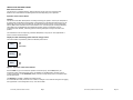
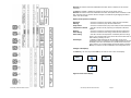
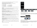
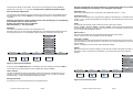
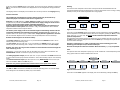
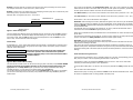
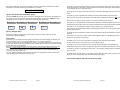
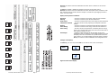
AS Control
Article number: 081037
INSTALLATION AND USER MANUAL
What is the AS Control?
The AS Control is a complete filtering, heating and solar energy control for swimming pools.
Read the entire manual before connecting the AS Control and putting it into operation!
Operation of the control cabinet
General
The AS Control has been developed for controlling swimming pool systems. The set pool temperature
is continuously monitored during the set filter running time(s) by operating the heating source or not.
Additionally, the control can be provided with an optional solar energy control. Various components
have by default been included in the control cabinet for this. A control program for Besgo backwash
valves takes care of backwashing and clearwashing the filter system in accordance with preprogrammed times. Besides, connecting options for dosing technique and surge tank control are
present.
The manufacturer will not accept any guarantee claim/liability in any way for other applications or
areas of use than mentioned above.
Display for filter and heating system and solar energy control
The control cabinet is operated by means of individual push buttons.
Filter
Off
On
Automatic
Heating
Off
On
Solar
Off
On
Figure 1. Operation of the control cabinet
With the Filter key you can switch the operation of the filter pump. In the OFF position, all
components (filter, heating and solar energy) are disabled. In the On position, the filter pump is
running continuously. In the Automatic position, the filter running time(s) is/are in accordance with
the set switch times.
The Heating key enables or disables the heating control.
If a switch has been made, there will be no reaction to changes or new switches during the set lagging
time (‘Hysteresis’ in the Configuration menu). The LED will blink.
AS Control, manual version 09-2012
Page 2
AS Control, manual version 05-2011
Page 15
Remark: This function cannot be enabled when the water sensor is defective or has not been
connected.
The Solar key enables or disables the operation of the solar energy heating control.
Remark: This function cannot be enabled when the water sensor/solar sensor is defective or has not
been connected. Here no reaction will follow changes or switches during the lagging time after a
switch. The LED will blink.
Display of the operation conditions
Operation
Filtering
Pump failure
Temperature reached
Heating
Solar heating
Solar cooling
Frost danger
: The LED is lit when the mains power supply has been connected.
: The LED is lit when the pump has been switched on.
: The LED is lit when the filter pump motor safety has been switched off.
: This LED is lit when the set (required) pool temperature has been
reached.
: The LED is lit when the conventional heating has been switched on.
: The LED is lit when the solar energy control has been switched on.
: This LED is lit when the temperature is exceeded (with solar energy
option). The connected solar energy control will cool the basin water if the
solar collector(s) allow(s) for this.
: Enabled at outside temperatures that have been pre-set in the
Configuration menu (0-5 degrees). If the outside temperature rises again,
this display will be lit as an indication of a possible threat of the solar
energy system. You can acknowledge and reset this alarm by pressing the
OK key. The function can also be disabled in the Configuration menu.
Settings in the display:
The Mode key, the arrow keys and the OK key are used for menu control in the display.
Mode
OK
Figure 2. Menu control display
AS Control, manual version 05-2011
Page 14
AS Control, manual version 09-2012
Page 3
After having switched on the control, the display will show the current time and date as well as the
temperature in the basin and the solar temperature. For example:
WE12:34 W28 S24C
Terminals 29, 30 are equal to terminals 27 and 28 for connecting a backwash valve and a surge tank
control.
Figure 3. Current time and temperature display
Pressing the Mode key will take you to the menu for setting the filter running times, the heating and
solar energy control, the backwash cycle and the system settings. By pressing the Mode key again,
the display will return to the current time and the swimming pool temperature.
Filter control
Heating
Solar
Backwash
Mode
Terminals 27, 28 form an interconnection that can be used to stop the filter pump. The pump will stop
when the connection is interrupted. These terminals are potential-free and they are usually used for
e.g. a backwash valve or a surge tank control.
System
OK
Figure 4. Selection menu
Terminals 31, 32 form a potential-free connection used for forced activation of the filter pump.
This connection is required for connecting a surge tank control. Usually this connection is NOT present.
Terminal 33 is an extra ground (for example, to protect the water and solar sensors).
Terminals 34, 35 are potential-free contacts used for switching on external equipment that must work
simultaneously with the filter pump. The contact is activated after the filter pump has been operated.
Terminals 36, 37 are potential-free contacts used for switching on or signalling heating.
The contact will be closed when the heating is activated (this contact is often used for direct control of
a central heating boiler).
With the arrow keys you can select the function that you want to change. Select the function
concerned by pressing the OK key.
Terminals 38, 39 are potential-free contacts that may be used for paying more attention to an alarm
condition.
The contact is closed in case of alarm. It can control a telephone alarm or a signalling lamp, siren, etc.
Filter control
Terminal 40: see terminal 24,25 (heater).
In this menu you can change the filter running times and the motor safety setting. For example, you
can set switch time 1 to 9 – 12 hours and switch time 2 to 14 – 18 hours as follows:
A total of 9 switch times can be programmed, of which 1 - 8 are regular switch times. Switch time 9 is
for the winter position if the winter position has been enabled. Only the set time of this switch time will
be used then (e.g. 15 minutes daily).
NOTE: The pre-programmed times for switching a filter on and off must always be on the same day.
Therefore it is NOT possible to start e.g. on Tuesday at 16.00 hours and to stop at 02.00 hours.
Then program: start Tuesday at 16.00 hours and stop at 23.59 hours and on Wednesday start at
00.01 hours and stop at 02.00 hours.
So, when switching overnight, always split into two parts. This also applies to the ALL position (the
option for applying the same switch time every day).
Terminals 41, 42, 43 are 24 V AC outputs for controlling a motor valve of the solar system.
41 is the closing control; 42 is the Gnd (0); 43 is the opening control.
Terminals 44, 45, 46: these contacts are for connecting an external display. Only digital data are
transmitted through these contacts. Terminal 44 is TXD; terminal 45 RXD and terminal 46 is Gnd (0)
Terminals 47, 48 are for connecting the water sensor. * (if necessary, terminal 46 can be combined
with 47 as well)
Terminals 48, 49: the solar sensor is connected to these contacts (if a solar system is used). Terminal
48 can be used as a joint Gnd for both the water and the solar sensors.
The connection diagram will be shown on the next page!
AS Control, manual version 09-2012
Page 4
AS Control, manual version 05-2011
Page 13
If the solar sensor has not been connected, the indication in the display will not be present either.
The AS Control has been secured on all outputs by means of fuses.
These fuses are to be found below the operating front.
If a fuse needs replacement, insert the correct value in order to guarantee safety.
The values are as follows:
F2
F3
F4
F5
=
=
=
=
0,16 A inert (primary)
10 A inert (R) pump
10 A inert (s) pump
10 A inert (T) pump
F6
F7
F8
F9
=
=
=
=
3.15
3.15
3.15
3.15
A
A
A
A
inert
inert
inert
inert
(dosing)
(backwash)
(solar)
(heater)
The printed circuit-board does not include any other settings or adjustments points subject to service.
Overload protect
Switch time 9
Switch time 8
Switch time 7
Switch time 6
Switch time 5
Switch time 4
Switch time 3
Switch time 2
Terminals:
Terminals 1, 2, 3, 4, 5 are for connecting the mains voltage. 1 is the ground; 2 is the zero; 3 is the
first phase (R); 4 is the second phase (S) and 5 is the third phase (T)
If no high-voltage current is used, the power supply is connected to terminal 1, 2, 3 or the ground,
zero and the first phase.
Terminals 6, 7, 8, 9, 10 are for connecting the filter pump. Terminal 6 is the ground terminal; 7 is the
zero and terminals 8, 9, 10 are the 3 phases.
Terminals 6, 7, 8 are used when using a single-phase pump. They are the ground, zero and the first
phase respectively. The zero is not used with a 3-phase pump!
Terminals 11, 12, 13 are the contacts for the dosing equipment; terminal 11 is the ground; 12 is the
phase and 13 is the zero.
Terminals 14, 15, 16, 17 are for connecting the backwash valves. Terminal 14 is the ground; 15 is the
phase that comes in at a backwash action; terminal 16 is a permanent phase (for any power supply
from a backwash automat); terminal 17 is the zero.
This means that when use is made of a Besgo valve, terminals 14, 15, 17 are used.
Terminals 18, 19, 20 are extra connections of a supply voltage, for example, to empower the potentialfree contacts.
The terminals are permanently live: 18 is the ground; 19 is the phase and 20 is the zero.
Terminals 21, 22, 23 are for connecting a solar valve or solar pump. Terminal 21 is the ground; 22 is
the phase and 23 is the zero.
These terminals are activated when the Backwash function has been enabled for another function in
the System/Configuration menu!
In this case terminal 21 is the ground; 22 is the phase for the CLEARWASH valve (Besgo) and terminal
23 is the zero.
Terminals 24, 25, 40 (ATTENTION: TERMINAL 40 IS ON THE HIGHER TERMINAL STRIP). Terminal 24
is the ground, 25 is the zero and 40 is the phase for the heating valve or the relay that switches on the
heating.
Terminal 26 is an extra ground connection.
AS Control, manual version 05-2011
Page 12
Switch time 1
Filter control
Heating
Solar
Mode
Backwash
System
OK
Figure 5. Menu function Filter control
If the menu function Filter control appears in the display, this can be selected by pressing the OK
key. The arrow keys are used for selecting switch time 1 or switch time 2. Pressing the OK key again
selects the respective function.
Switch time 1
Stop
WE12:00
Start
WE09:00
Figure 6. Menu function Switch time
With the arrow keys you can check the switch on or switch off times. You can change the displayed
values by pressing the OK key. The time display starts blinking and can be changed using the arrow
keys. Press the OK key again to save the changed value. Press the Mode key if no changes are
required. The old value will remain unchanged.
AS Control, manual version 09-2012
Page 5
Remark: If the start and end of a switch time have the same value, this setting will not be carried
out. Example: Switch time 1: start 9:00 hours / end 9:00 hours.
Remark: If switch time 1 and switch time 2 are overlapping, the filter pump will run continuously until
both running times / cycles have been completed.
Example: Filter running time 8:00 hours – 16:00 hours.
The Δt solar can be adjusted in the Configuration menu. This is set to 3ºC by default. The setting
means that the set value is the bottom limit for putting the solar system into operation, provided that
the solar option has been enabled. The value can be set between 3ºC and 10ºC.
With Water sensor you can correct a minor deviation of the water sensor (maximum + and – 5ºC).
With Solar sensor you can correct a minor deviation of the solar sensor (maximum + and – 5ºC).
Switch time 2
12:00 hour
08:00 hour
16:00 hour
Backwash: When selecting this function, Backwash will appear in the main menu (see the Backwash
section). When this function is disabled, the menu will disappear as well. Please keep in mind that the
connection SOLAR is cancelled when enabling the backwash menu, as this will become the connection
for the backwash valve.
The backwash valve is connected to the terminals 15, 16 and 17, whereas the clearwash valve is
connected to the terminals SOLAR 22 (phase) and 23 (zero).
12:30 hour
Switch time 1
Figure 7. Filter running time
The hour display starts blinking and can be changed using the arrow keys. Press the OK key again to
save the changed value. The minutes display will start blinking now. This can be changed using the
arrow keys as well. Press the OK key again to save the changed value. Press the Mode key if you
want to stop. The old value will remain unchanged.
Motor safety
An adjustable (0.7 - 9.9 A) motor safety protects the three-phase or the alternate current filter pump
against overload damage. When using a pump with a higher power consumption, apply an external
relay with motor safety switch.
Current
1,0 A
Adjust
Remark: The motor safety must be set before putting the
control into operation. The consumed current (nominal
current) of the filter pump is to be measured and checked in
a loaded condition.
When using a backwash automat, the Backwash menu can be disabled. The control will then be done
by the valve.
The automat is connected to the terminals 15, 16 and 17 (power supply for the valve) and the filter
pump is controlled on the Safety switches terminals 27 and 28 (open contact).
Hysteresis: This value can be set between 0 and 9.5 minutes.
This value determines the lagging time of the filter pump when the end of the filter time has been
reached and the heating is still active.
This time is also used for absorbing temperature fluctuations at switching on Heating or Solar. No
attention will be paid to temperature fluctuations during the set time, as this has been made visible
through the blinking LED of the switch (this also prevents so-called “pendulum” of the solar control or
heating).
Some instructions for general use:
If the AS Control is connected to 230 V, terminals N and R are to be used. Correspondingly, the 230V
filter pump on N and R of the corresponding terminal block is used as well.
Overload protect
Figure 8. Menu function Motor safety
If the heating is active, the potential-free heater contact will come in. This can be useful when
controlling a central heating system or other applications.
The value for the nominal current can be found on the type plate of the filter pump. Remark: NEVER
set the set nominal current higher than 10% of the current strength mentioned on the
type plate! The LED Pump failure lights up when the motor safety is activated. After having
remedied the failure, you can switch on the system again using the Filter key.
You can also have the AS Control set the motor current automatically. If this option is not selected,
you will have to manually switch on the filter pump. Validate the value using the OK key after the
measurement.
AS Control, manual version 09-2012
Serial number: this is for the information of the supplier.
Page 6
If a pump failure takes place or in case of a risk of frost, the potential-free safety contact will come
in.
This can switch off an external alarm.
When the filter pump is running, the potential-free filter contact has been activated as well. This can
be used for an application that is running parallel to the filter pump.
AS Control, manual version 05-2011
Page 11
If the menu function System appears in the display, the current time can be selected by pressing the
OK key. The set time can be checked. This displayed time can be changed after having pressed the
OK key.
The language shown in the display can be selected here as well by means of the Language setting.
Heating
The minimum water temperature of the basin is always monitored and maintained when the
conventional heating has been connected and/or is working, because this source of energy is always
available, contrary to the weather-dependent solar energy system.
Electric connection
!!The building in and installation of electric devices should only be carried out by
authorised people in accordance with the local regulations!!
Attention: In the Off position(s) of Filter, Heating and Solar not all terminals in the connection
compartment are potential-free! Disconnect/switch off the supply voltage of the AS Control
in order to protect the system against unintended switching on.
Attention: Disconnect/switch off the supply voltage when carrying out maintenance or
repair activities on the system! Install the unit in a dry, well-ventilated room with an ambient
temperature between 5 and 40 degrees Celsius.
The electric power supply must be connected through an earth leakage switch of 30 mA
(separately installed for the swimming pool system). Pre-fuse max. 16 A. Additionally, an
operation switch in the power supply is recommended. Comply with the regulations in all cases.
See the connection diagram for the connection of all components/devices to the terminal strip.
Remark: Do NOT forget to set the motor safety!
The heating output (220-240 V/AC max. 2.0 A) is connected to the HEATER terminals. Use an
auxiliary relay for more switching power.
The solar output (220-240 V/AC max. 2.0 A) is connected to the SOLAR terminals. Use an extra
auxiliary relay for more switching power. Usually a motor valve is connected to the solar output.
Remark: The motor valve is given the command to let the filtered water flow through the
solar collector(s) or not.
Alternatively, a 3-way motor valve 24 V/AC can be applied. This motor valve is connected to the
MOTOR VALVE terminals. Terminal 41 is open; 42 is Gnd; 43 is closed.
The dosing equipment output (220-240 V/AC max. 2.0 A) is connected to the DOSE terminals and
it is active when the filter pump has been switched on. Use an extra auxiliary relay for more switching
power.
The backwash automat output (220-240 V/AC max. 2.0 A) WASH always sends out 220 V/AC
when the LED On or Auto of the Filter key is lit.
Attention: Only connect potential-free switch contacts to the inputs of the SAFETY
SWITCHES terminals! Do not connect live wires/cables!
Temp. Min 20ºC
Filter control
Heating
Solar
Mode
Backwash
System
OK
Figure 9. Menu function Heating
If the menu function Heating appears in the display, this can be selected by pressing the OK key.
The set temperature can be checked and the value can be changed by pressing the OK key. Setting
range: Temp min. </= Temp. Opt. So always set this minimum temperature below the
optimum temperature!
The temperature starts blinking and the set temperature can be changed using the arrow keys. Press
the OK key again to save the changed value. Press the Mode key if no changes are required. The old
value will remain unchanged.
Attention: Temperatures of > 28ºC can damage parts of the swimming pool or the
swimming pool technique and/or shorten its life span.
Remark: The temperature data are indicative. Minor deviations (+/- 2ºC) are possible.
Solar
The optimum basin water temperature (Temp.opt.) can be reached with a connected/working solar
energy system when the weather conditions allow for this.
Temp.opt. 28ºC
Filter control
Heating
Mode
Solar
Backwash
System
OK
The TXD and RXD connections are intended for an external operating panel or an external display.
Some settings are not accessible by default, only to the installer.
Figure 10. Menu function Solar
If the menu function Solar appears in the display, this can be selected by pressing the OK key.
AS Control, manual version 05-2011
Page 10
AS Control, manual version 09-2012
Page 7
The temperature setting can be checked. The set value can be changed by pressing the OK key.
Setting range: Temp. Opt. >/= Temp. Min. So always set the optimum temperature higher
than the minimum temperature!
The temperature starts blinking and can be changed using the arrow keys. Press the OK key again to
save the changed value. Press the Mode key if no changes are required. The old value will remain
unchanged.
Attention: Temperatures > 28ºC can damage parts of the swimming pool or the swimming
pool technique and/or shorten its life span.
Remark: The temperature data are indicative.
Minor deviations (+/- 2ºC) are possible.
Backwash
The installer can enable this function in the Configuration menu.
With this function you can control an Besgo backwash valve. The backwash and clearwash cycles can
be set through this menu. The corresponding magnetic valves are connected in the switch box.
Test (Man.)+Reset
BwCw in days
1
Pauze
Off
Clearwash 0,5
min
Backwash
min
Starttime
3
Filter control
Heating
Solar
Backwash
Backwash 3 min
In this menu the backwash time is programmed. The possible intervals are 0 – 30 min.
Clearwash 0.5 min
In this menu the clearwash cycle is programmed by setting the clearwash time. The possible intervals
are OFF – 5 min. The OFF setting disables the clearwash cycle. The Clearwash time cannot be set from
the OFF position.
Pause
The backwash and clearwash cycles include three pauses. These look as follows:
Filtering – Pause – Backwash – Pause – Clearwash – Pause – Filtering. Here all three pauses are of
the same duration. However, the duration of the pauses can be set. The possible intervals are OFF –
10 min. The OFF setting disables the pauses.
BwCw in days 1
This menu item indicates when the next backwash/clearwash cycle will be started.
Remark: The day counter will be updated every day at midnight.
Test (Man.) + RESET
In this menu item you can manually enable the backwash cycle and reset the day counter as well. The
manual backwashing starts after expiration of a full minute. The remaining waiting time can be read
from the display.
Remark: The display of the day counter will be updated at midnight.
System
09:00
Interv. Days
Remark: The backwash cycle must be within the programmed filter times. If you want to
program something else, the message ‘error’ will appear in the display.
01
System
Setting the current time. Thanks to a battery, the set time will be saved in the system even after a
power failure. Bear in mind that time is limited here. The summer/winter time must be adjusted
manually.
Winter
Mode
OFF
Recall Default
OK
Set Default
Language
Figure 11. Menu function Backwash
English
Configuration
If the menu function Backwash appears in the display, this can be selected by pressing the OK key.
The set values can be checked and they can be changed by pressing the OK key.
Interv. Days 01
This interval indicates the number of days that is between the starting of the backwash cycle. For
example, 10 days. This means that the backwash cycle is carried out every 10 days. The possible
intervals are OFF – 30 days. OFF disables the backwash program.
Starting time 09:00
In this menu you can enter the starting time for the backwash cycle.
AS Control, manual version 09-2012
Page 8
Time
Filter control
Heating
Mode
Solar
Backwash
OK
Figure 12. Menu function System
AS Control, manual version 05-2011
Page 9
WE12:45
System
The temperature setting can be checked. The set value can be changed by pressing the OK key.
Setting range: Temp. Opt. >/= Temp. Min. So always set the optimum temperature higher
than the minimum temperature!
The temperature starts blinking and can be changed using the arrow keys. Press the OK key again to
save the changed value. Press the Mode key if no changes are required. The old value will remain
unchanged.
Attention: Temperatures > 28ºC can damage parts of the swimming pool or the swimming
pool technique and/or shorten its life span.
Remark: The temperature data are indicative.
Minor deviations (+/- 2ºC) are possible.
Backwash
The installer can enable this function in the Configuration menu.
With this function you can control an Besgo backwash valve. The backwash and clearwash cycles can
be set through this menu. The corresponding magnetic valves are connected in the switch box.
Test (Man.)+Reset
BwCw in days
1
Pauze
Off
Clearwash 0,5
min
Backwash
min
Starttime
3
Filter control
Heating
Solar
Backwash
Backwash 3 min
In this menu the backwash time is programmed. The possible intervals are 0 – 30 min.
Clearwash 0.5 min
In this menu the clearwash cycle is programmed by setting the clearwash time. The possible intervals
are OFF – 5 min. The OFF setting disables the clearwash cycle. The Clearwash time cannot be set from
the OFF position.
Pause
The backwash and clearwash cycles include three pauses. These look as follows:
Filtering – Pause – Backwash – Pause – Clearwash – Pause – Filtering. Here all three pauses are of
the same duration. However, the duration of the pauses can be set. The possible intervals are OFF –
10 min. The OFF setting disables the pauses.
BwCw in days 1
This menu item indicates when the next backwash/clearwash cycle will be started.
Remark: The day counter will be updated every day at midnight.
Test (Man.) + RESET
In this menu item you can manually enable the backwash cycle and reset the day counter as well. The
manual backwashing starts after expiration of a full minute. The remaining waiting time can be read
from the display.
Remark: The display of the day counter will be updated at midnight.
System
09:00
Interv. Days
Remark: The backwash cycle must be within the programmed filter times. If you want to
program something else, the message ‘error’ will appear in the display.
01
System
Setting the current time. Thanks to a battery, the set time will be saved in the system even after a
power failure. Bear in mind that time is limited here. The summer/winter time must be adjusted
manually.
Winter
Mode
OFF
Recall Default
OK
Set Default
Language
Figure 11. Menu function Backwash
English
Configuration
If the menu function Backwash appears in the display, this can be selected by pressing the OK key.
The set values can be checked and they can be changed by pressing the OK key.
Interv. Days 01
This interval indicates the number of days that is between the starting of the backwash cycle. For
example, 10 days. This means that the backwash cycle is carried out every 10 days. The possible
intervals are OFF – 30 days. OFF disables the backwash program.
Starting time 09:00
In this menu you can enter the starting time for the backwash cycle.
AS Control, manual version 05-2011
Page 8
Time
Filter control
Heating
Mode
Solar
Backwash
OK
Figure 12. Menu function System
AS Control, manual version 09-2012
Page 9
WE12:45
System
If the menu function System appears in the display, the current time can be selected by pressing the
OK key. The set time can be checked. This displayed time can be changed after having pressed the
OK key.
The language shown in the display can be selected here as well by means of the Language setting.
Heating
The minimum water temperature of the basin is always monitored and maintained when the
conventional heating has been connected and/or is working, because this source of energy is always
available, contrary to the weather-dependent solar energy system.
Electric connection
!!The building in and installation of electric devices should only be carried out by
authorised people in accordance with the local regulations!!
Attention: In the Off position(s) of Filter, Heating and Solar not all terminals in the connection
compartment are potential-free! Disconnect/switch off the supply voltage of the AS Control
in order to protect the system against unintended switching on.
Attention: Disconnect/switch off the supply voltage when carrying out maintenance or
repair activities on the system! Install the unit in a dry, well-ventilated room with an ambient
temperature between 5 and 40 degrees Celsius.
The electric power supply must be connected through an earth leakage switch of 30 mA
(separately installed for the swimming pool system). Pre-fuse max. 16 A. Additionally, an
operation switch in the power supply is recommended. Comply with the regulations in all cases.
See the connection diagram for the connection of all components/devices to the terminal strip.
Remark: Do NOT forget to set the motor safety!
The heating output (220-240 V/AC max. 2.0 A) is connected to the HEATER terminals. Use an
auxiliary relay for more switching power.
The solar output (220-240 V/AC max. 2.0 A) is connected to the SOLAR terminals. Use an extra
auxiliary relay for more switching power. Usually a motor valve is connected to the solar output.
Remark: The motor valve is given the command to let the filtered water flow through the
solar collector(s) or not.
Alternatively, a 3-way motor valve 24 V/AC can be applied. This motor valve is connected to the
MOTOR VALVE terminals. Terminal 41 is open; 42 is Gnd; 43 is closed.
The dosing equipment output (220-240 V/AC max. 2.0 A) is connected to the DOSE terminals and
it is active when the filter pump has been switched on. Use an extra auxiliary relay for more switching
power.
The backwash automat output (220-240 V/AC max. 2.0 A) WASH always sends out 220 V/AC
when the LED On or Auto of the Filter key is lit.
Attention: Only connect potential-free switch contacts to the inputs of the SAFETY
SWITCHES terminals! Do not connect live wires/cables!
Temp. Min 20ºC
Filter control
Heating
Solar
Mode
Backwash
System
OK
Figure 9. Menu function Heating
If the menu function Heating appears in the display, this can be selected by pressing the OK key.
The set temperature can be checked and the value can be changed by pressing the OK key. Setting
range: Temp min. </= Temp. Opt. So always set this minimum temperature below the
optimum temperature!
The temperature starts blinking and the set temperature can be changed using the arrow keys. Press
the OK key again to save the changed value. Press the Mode key if no changes are required. The old
value will remain unchanged.
Attention: Temperatures of > 28ºC can damage parts of the swimming pool or the
swimming pool technique and/or shorten its life span.
Remark: The temperature data are indicative. Minor deviations (+/- 2ºC) are possible.
Solar
The optimum basin water temperature (Temp.opt.) can be reached with a connected/working solar
energy system when the weather conditions allow for this.
Temp.opt. 28ºC
Filter control
Heating
Mode
Solar
Backwash
System
OK
The TXD and RXD connections are intended for an external operating panel or an external display.
Some settings are not accessible by default, only to the installer.
Figure 10. Menu function Solar
If the menu function Solar appears in the display, this can be selected by pressing the OK key.
AS Control, manual version 09-2012
Page 10
AS Control, manual version 05-2011
Page 7
Remark: If the start and end of a switch time have the same value, this setting will not be carried
out. Example: Switch time 1: start 9:00 hours / end 9:00 hours.
Remark: If switch time 1 and switch time 2 are overlapping, the filter pump will run continuously until
both running times / cycles have been completed.
Example: Filter running time 8:00 hours – 16:00 hours.
The Δt solar can be adjusted in the Configuration menu. This is set to 3ºC by default. The setting
means that the set value is the bottom limit for putting the solar system into operation, provided that
the solar option has been enabled. The value can be set between 3ºC and 10ºC.
With Water sensor you can correct a minor deviation of the water sensor (maximum + and – 5ºC).
With Solar sensor you can correct a minor deviation of the solar sensor (maximum + and – 5ºC).
Switch time 2
12:00 hour
08:00 hour
16:00 hour
Backwash: When selecting this function, Backwash will appear in the main menu (see the Backwash
section). When this function is disabled, the menu will disappear as well. Please keep in mind that the
connection SOLAR is cancelled when enabling the backwash menu, as this will become the connection
for the backwash valve.
The backwash valve is connected to the terminals 15, 16 and 17, whereas the clearwash valve is
connected to the terminals SOLAR 22 (phase) and 23 (zero).
12:30 hour
Switch time 1
Figure 7. Filter running time
The hour display starts blinking and can be changed using the arrow keys. Press the OK key again to
save the changed value. The minutes display will start blinking now. This can be changed using the
arrow keys as well. Press the OK key again to save the changed value. Press the Mode key if you
want to stop. The old value will remain unchanged.
Motor safety
An adjustable (0.7 - 9.9 A) motor safety protects the three-phase or the alternate current filter pump
against overload damage. When using a pump with a higher power consumption, apply an external
relay with motor safety switch.
Current
1,0 A
Adjust
Remark: The motor safety must be set before putting the
control into operation. The consumed current (nominal
current) of the filter pump is to be measured and checked in
a loaded condition.
When using a backwash automat, the Backwash menu can be disabled. The control will then be done
by the valve.
The automat is connected to the terminals 15, 16 and 17 (power supply for the valve) and the filter
pump is controlled on the Safety switches terminals 27 and 28 (open contact).
Hysteresis: This value can be set between 0 and 9.5 minutes.
This value determines the lagging time of the filter pump when the end of the filter time has been
reached and the heating is still active.
This time is also used for absorbing temperature fluctuations at switching on Heating or Solar. No
attention will be paid to temperature fluctuations during the set time, as this has been made visible
through the blinking LED of the switch (this also prevents so-called “pendulum” of the solar control or
heating).
Some instructions for general use:
If the AS Control is connected to 230 V, terminals N and R are to be used. Correspondingly, the 230V
filter pump on N and R of the corresponding terminal block is used as well.
Overload protect
Figure 8. Menu function Motor safety
If the heating is active, the potential-free heater contact will come in. This can be useful when
controlling a central heating system or other applications.
The value for the nominal current can be found on the type plate of the filter pump. Remark: NEVER
set the set nominal current higher than 10% of the current strength mentioned on the
type plate! The LED Pump failure lights up when the motor safety is activated. After having
remedied the failure, you can switch on the system again using the Filter key.
You can also have the AS Control set the motor current automatically. If this option is not selected,
you will have to manually switch on the filter pump. Validate the value using the OK key after the
measurement.
AS Control, manual version 05-2011
Serial number: this is for the information of the supplier.
Page 6
If a pump failure takes place or in case of a risk of frost, the potential-free safety contact will come
in.
This can switch off an external alarm.
When the filter pump is running, the potential-free filter contact has been activated as well. This can
be used for an application that is running parallel to the filter pump.
AS Control, manual version 09-2012
Page 11
If the solar sensor has not been connected, the indication in the display will not be present either.
The AS Control has been secured on all outputs by means of fuses.
These fuses are to be found below the operating front.
If a fuse needs replacement, insert the correct value in order to guarantee safety.
The values are as follows:
F2
F3
F4
F5
=
=
=
=
0,16 A inert (primary)
10 A inert (R) pump
10 A inert (s) pump
10 A inert (T) pump
F6
F7
F8
F9
=
=
=
=
3.15
3.15
3.15
3.15
A
A
A
A
inert
inert
inert
inert
(dosing)
(backwash)
(solar)
(heater)
The printed circuit-board does not include any other settings or adjustments points subject to service.
Overload protect
Switch time 9
Switch time 8
Switch time 7
Switch time 6
Switch time 5
Switch time 4
Switch time 3
Switch time 2
Terminals:
Terminals 1, 2, 3, 4, 5 are for connecting the mains voltage. 1 is the ground; 2 is the zero; 3 is the
first phase (R); 4 is the second phase (S) and 5 is the third phase (T)
If no high-voltage current is used, the power supply is connected to terminal 1, 2, 3 or the ground,
zero and the first phase.
Terminals 6, 7, 8, 9, 10 are for connecting the filter pump. Terminal 6 is the ground terminal; 7 is the
zero and terminals 8, 9, 10 are the 3 phases.
Terminals 6, 7, 8 are used when using a single-phase pump. They are the ground, zero and the first
phase respectively. The zero is not used with a 3-phase pump!
Terminals 11, 12, 13 are the contacts for the dosing equipment; terminal 11 is the ground; 12 is the
phase and 13 is the zero.
Terminals 14, 15, 16, 17 are for connecting the backwash valves. Terminal 14 is the ground; 15 is the
phase that comes in at a backwash action; terminal 16 is a permanent phase (for any power supply
from a backwash automat); terminal 17 is the zero.
This means that when use is made of a Besgo valve, terminals 14, 15, 17 are used.
Terminals 18, 19, 20 are extra connections of a supply voltage, for example, to empower the potentialfree contacts.
The terminals are permanently live: 18 is the ground; 19 is the phase and 20 is the zero.
Terminals 21, 22, 23 are for connecting a solar valve or solar pump. Terminal 21 is the ground; 22 is
the phase and 23 is the zero.
These terminals are activated when the Backwash function has been enabled for another function in
the System/Configuration menu!
In this case terminal 21 is the ground; 22 is the phase for the CLEARWASH valve (Besgo) and terminal
23 is the zero.
Terminals 24, 25, 40 (ATTENTION: TERMINAL 40 IS ON THE HIGHER TERMINAL STRIP). Terminal 24
is the ground, 25 is the zero and 40 is the phase for the heating valve or the relay that switches on the
heating.
Terminal 26 is an extra ground connection.
AS Control, manual version 09-2012
Page 12
Switch time 1
Filter control
Heating
Solar
Mode
Backwash
System
OK
Figure 5. Menu function Filter control
If the menu function Filter control appears in the display, this can be selected by pressing the OK
key. The arrow keys are used for selecting switch time 1 or switch time 2. Pressing the OK key again
selects the respective function.
Switch time 1
Stop
WE12:00
Start
WE09:00
Figure 6. Menu function Switch time
With the arrow keys you can check the switch on or switch off times. You can change the displayed
values by pressing the OK key. The time display starts blinking and can be changed using the arrow
keys. Press the OK key again to save the changed value. Press the Mode key if no changes are
required. The old value will remain unchanged.
AS Control, manual version 05-2011
Page 5
After having switched on the control, the display will show the current time and date as well as the
temperature in the basin and the solar temperature. For example:
WE12:34 W28 S24C
Terminals 29, 30 are equal to terminals 27 and 28 for connecting a backwash valve and a surge tank
control.
Figure 3. Current time and temperature display
Pressing the Mode key will take you to the menu for setting the filter running times, the heating and
solar energy control, the backwash cycle and the system settings. By pressing the Mode key again,
the display will return to the current time and the swimming pool temperature.
Filter control
Heating
Solar
Backwash
Mode
Terminals 27, 28 form an interconnection that can be used to stop the filter pump. The pump will stop
when the connection is interrupted. These terminals are potential-free and they are usually used for
e.g. a backwash valve or a surge tank control.
System
OK
Figure 4. Selection menu
Terminals 31, 32 form a potential-free connection used for forced activation of the filter pump.
This connection is required for connecting a surge tank control. Usually this connection is NOT present.
Terminal 33 is an extra ground (for example, to protect the water and solar sensors).
Terminals 34, 35 are potential-free contacts used for switching on external equipment that must work
simultaneously with the filter pump. The contact is activated after the filter pump has been operated.
Terminals 36, 37 are potential-free contacts used for switching on or signalling heating.
The contact will be closed when the heating is activated (this contact is often used for direct control of
a central heating boiler).
With the arrow keys you can select the function that you want to change. Select the function
concerned by pressing the OK key.
Terminals 38, 39 are potential-free contacts that may be used for paying more attention to an alarm
condition.
The contact is closed in case of alarm. It can control a telephone alarm or a signalling lamp, siren, etc.
Filter control
Terminal 40: see terminal 24,25 (heater).
In this menu you can change the filter running times and the motor safety setting. For example, you
can set switch time 1 to 9 – 12 hours and switch time 2 to 14 – 18 hours as follows:
A total of 9 switch times can be programmed, of which 1 - 8 are regular switch times. Switch time 9 is
for the winter position if the winter position has been enabled. Only the set time of this switch time will
be used then (e.g. 15 minutes daily).
NOTE: The pre-programmed times for switching a filter on and off must always be on the same day.
Therefore it is NOT possible to start e.g. on Tuesday at 16.00 hours and to stop at 02.00 hours.
Then program: start Tuesday at 16.00 hours and stop at 23.59 hours and on Wednesday start at
00.01 hours and stop at 02.00 hours.
So, when switching overnight, always split into two parts. This also applies to the ALL position (the
option for applying the same switch time every day).
Terminals 41, 42, 43 are 24 V AC outputs for controlling a motor valve of the solar system.
41 is the closing control; 42 is the Gnd (0); 43 is the opening control.
Terminals 44, 45, 46: these contacts are for connecting an external display. Only digital data are
transmitted through these contacts. Terminal 44 is TXD; terminal 45 RXD and terminal 46 is Gnd (0)
Terminals 47, 48 are for connecting the water sensor. * (if necessary, terminal 46 can be combined
with 47 as well)
Terminals 48, 49: the solar sensor is connected to these contacts (if a solar system is used). Terminal
48 can be used as a joint Gnd for both the water and the solar sensors.
The connection diagram will be shown on the next page!
AS Control, manual version 05-2011
Page 4
AS Control, manual version 09-2012
Page 13
Remark: This function cannot be enabled when the water sensor is defective or has not been
connected.
The Solar key enables or disables the operation of the solar energy heating control.
Remark: This function cannot be enabled when the water sensor/solar sensor is defective or has not
been connected. Here no reaction will follow changes or switches during the lagging time after a
switch. The LED will blink.
Display of the operation conditions
Operation
Filtering
Pump failure
Temperature reached
Heating
Solar heating
Solar cooling
Frost danger
: The LED is lit when the mains power supply has been connected.
: The LED is lit when the pump has been switched on.
: The LED is lit when the filter pump motor safety has been switched off.
: This LED is lit when the set (required) pool temperature has been
reached.
: The LED is lit when the conventional heating has been switched on.
: The LED is lit when the solar energy control has been switched on.
: This LED is lit when the temperature is exceeded (with solar energy
option). The connected solar energy control will cool the basin water if the
solar collector(s) allow(s) for this.
: Enabled at outside temperatures that have been pre-set in the
Configuration menu (0-5 degrees). If the outside temperature rises again,
this display will be lit as an indication of a possible threat of the solar
energy system. You can acknowledge and reset this alarm by pressing the
OK key. The function can also be disabled in the Configuration menu.
Settings in the display:
The Mode key, the arrow keys and the OK key are used for menu control in the display.
Mode
OK
Figure 2. Menu control display
AS Control, manual version 09-2012
Page 14
AS Control, manual version 05-2011
Page 3
INSTALLATION AND USER MANUAL
What is the AS Control?
The AS Control is a complete filtering, heating and solar energy control for swimming pools.
Read the entire manual before connecting the AS Control and putting it into operation!
Operation of the control cabinet
General
The AS Control has been developed for controlling swimming pool systems. The set pool temperature
is continuously monitored during the set filter running time(s) by operating the heating source or not.
Additionally, the control can be provided with an optional solar energy control. Various components
have by default been included in the control cabinet for this. A control program for Besgo backwash
valves takes care of backwashing and clearwashing the filter system in accordance with preprogrammed times. Besides, connecting options for dosing technique and surge tank control are
present.
The manufacturer will not accept any guarantee claim/liability in any way for other applications or
areas of use than mentioned above.
Display for filter and heating system and solar energy control
The control cabinet is operated by means of individual push buttons.
Filter
Off
On
Automatic
Heating
Off
On
Solar
Off
On
Figure 1. Operation of the control cabinet
With the Filter key you can switch the operation of the filter pump. In the OFF position, all
components (filter, heating and solar energy) are disabled. In the On position, the filter pump is
running continuously. In the Automatic position, the filter running time(s) is/are in accordance with
the set switch times.
The Heating key enables or disables the heating control.
If a switch has been made, there will be no reaction to changes or new switches during the set lagging
time (‘Hysteresis’ in the Configuration menu). The LED will blink.
AS Control, manual version 05-2011
Page 2
AS Control, manual version 09-2012
Page 15
AS Control
Article number: 081037