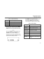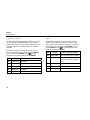
1
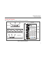
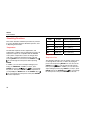
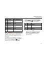
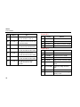
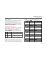
PS420 Multiparameter Simulator Users Manual PN 2631808 April 2006, Rev. 1, 12/07 © 2006, 2007 Fluke Corporation, All rights reserved. Specifications are subject to ochange without notice. Printed in USA All product names are trademarks of their respective companies. Warranty and Product Support Fluke Biomedical warrants this instrument against defects in materials and workmanship for one full year from the date of original purchase. During the warranty period, we will repair or, at our option, replace at no charge a product that proves to be defective, provided you return the product, shipping prepaid, to Fluke Biomedical. This warranty does not apply if the product has been damaged by accident or misuse or as the result of service or modification by other than Fluke Biomedical. IN NO EVENT SHALL FLUKE BIOMEDICAL BE LIABLE FOR CONSEQUENTIAL DAMAGES. Only serialized products and their accessory items (those products and items bearing a distinct serial number tag) are covered under this one–year warranty. PHYSICAL DAMAGE CAUSED BY MISUSE OR PHYSICAL ABUSE IS NOT COVERED UNDER THE WARRANTY. Items such as cables and nonserialized modules are not covered under this warranty. Recalibration of instruments is not covered under the warranty. This warranty gives you specific legal rights, and you may also have other rights which vary from state to state, province to province, or country to country. This warranty is limited to repairing the instrument to Fluke Biomedical’s specifications. Warranty Disclaimer Should you elect to have your instrument serviced and/or calibrated by someone other than Fluke Biomedical, please be advised that the original warranty covering your product becomes void when the tamper-resistant Quality Seal is removed or broken without proper factory authorization. We strongly recommend, therefore, that you send your instrument to Fluke Biomedical for factory service and calibration, especially during the original warranty period. Notices All Rights Reserved © Copyright 2006, Fluke Biomedical. No part of this publication may be reproduced, transmitted, transcribed, stored in a retrieval system, or translated into any language without the written permission of Fluke Biomedical. Copyright Release Fluke Biomedical agrees to a limited copyright release that allows you to reproduce manuals and other printed materials for use in service training programs and other technical publications. If you would like other reproductions or distributions, submit a written request to Fluke Biomedical. Unpacking and Inspection Follow standard receiving practices upon receipt of the instrument. Check the shipping carton for damage. If damage is found, stop unpacking the instrument. Notify the carrier and ask for an agent to be present while the instrument is unpacked. There are no special unpacking instructions, but be careful not to damage the instrument when unpacking it. Inspect the instrument for physical damage such as bent or broken parts, dents, or scratches. Technical Support For application support or answers to technical questions, either email [email protected] or call 1-800- 648-7952 or 1-425-446-6945. Claims Our routine method of shipment is via common carrier, FOB origin. Upon delivery, if physical damage is found, retain all packing materials in their original condition and contact the carrier immediately to file a claim. If the instrument is delivered in good physical condition but does not operate within specifications, or if there are any other problems not caused by shipping damage, please contact Fluke Biomedical or your local sales representative. Standard Terms and Conditions Refunds and Credits Please note that only serialized products and their accessory items (i.e., products and items bearing a distinct serial number tag) are eligible for partial refund and/or credit. Nonserialized parts and accessory items (e.g., cables, carrying cases, auxiliary modules, etc.) are not eligible for return or refund. Only products returned within 90 days from the date of original purchase are eligible for refund/credit. In order to receive a partial refund/credit of a product purchase price on a serialized product, the product must not have been damaged by the customer or by the carrier chosen by the customer to return the goods, and the product must be returned complete (meaning with all manuals, cables, accessories, etc.) and in “as new” and resalable condition. Products not returned within 90 days of purchase, or products which are not in “as new” and resalable condition, are not eligible for credit return and will be returned to the customer. The Return Procedure (see below) must be followed to assure prompt refund/credit. Restocking Charges Products returned within 30 days of original purchase are subject to a minimum restocking fee of 15 %. Products returned in excess of 30 days after purchase, but prior to 90 days, are subject to a minimum restocking fee of 20 %. Additional charges for damage and/or missing parts and accessories will be applied to all returns. Return Procedure All items being returned (including all warranty-claim shipments) must be sent freight-prepaid to our factory location. When you return an instrument to Fluke Biomedical, we recommend using United Parcel Service, Federal Express, or Air Parcel Post. We also recommend that you insure your shipment for its actual replacement cost. Fluke Biomedical will not be responsible for lost shipments or instruments that are received in damaged condition due to improper packaging or handling. Use the original carton and packaging material for shipment. If they are not available, we recommend the following guide for repackaging: Use a double–walled carton of sufficient strength for the weight being shipped. Use heavy paper or cardboard to protect all instrument surfaces. Use nonabrasive material around all projecting parts. Use at least four inches of tightly packed, industry-approved, shock-absorbent material around the instrument. Returns for partial refund/credit: Every product returned for refund/credit must be accompanied by a Return Material Authorization (RMA) number, obtained from our Order Entry Group at 1-800-648-7952 or 1-425-446-6945. Repair and calibration: To find the nearest service center, go to www.flukebiomedical.com/service or In the U.S.A.: Cleveland Calibration Lab Tel: 1-800-850-4606 Email: [email protected] Everett Calibration Lab Tel: 1-800-850-4606 Email: [email protected] In Europe, Middle East, and Africa: Eindhoven Calibration Lab Tel: +31-402-675300 Email: [email protected] In Asia: Everett Calibration Lab Tel: +425-446-6945 Email: [email protected] Certification This instrument was thoroughly tested and inspected. It was found to meet Fluke Biomedical’s manufacturing specifications when it was shipped from the factory. Calibration measurements are traceable to the National Institute of Standards and Technology (NIST). Devices for which there are no NIST calibration standards are measured against in-house performance standards using accepted test procedures. WARNING Unauthorized user modifications or application beyond the published specifications may result in electrical shock hazards or improper operation. Fluke Biomedical will not be responsible for any injuries sustained due to unauthorized equipment modifications. Restrictions and Liabilities Information in this document is subject to change and does not represent a commitment by Fluke Biomedical. Changes made to the information in this document will be incorporated in new editions of the publication. No responsibility is assumed by Fluke Biomedical for the use or reliability of software or equipment that is not supplied by Fluke Biomedical, or by its affiliated dealers. Manufacturing Location The PS420 Multiparameter Simulator is manufactured by Fluke Biomedical, 6045 Cochran Rd. Cleveland, Ohio 44139. Table of Contents Title Introduction .................................................................................................................... Safety ............................................................................................................................. Specifications ................................................................................................................. General...................................................................................................................... Accessories ............................................................................................................... ECG........................................................................................................................... Pacemaker Selections ............................................................................................... Arrhythmia Selections................................................................................................ Blood Pressure .......................................................................................................... Cardiac Output Option............................................................................................... Respiration ................................................................................................................ Temperature .............................................................................................................. Controls and Terminals .................................................................................................. Powering the Simulator .................................................................................................. Operating the Simulator ................................................................................................. Simulating Functions ...................................................................................................... Temperature .............................................................................................................. i Page 1 1 3 3 4 4 5 6 7 8 8 8 9 13 13 16 16 PS420 Users Manual Respiration................................................................................................................ Respiration Rate................................................................................................... Baseline Impedance............................................................................................. Impedance Variations........................................................................................... Apnea................................................................................................................... Blood Pressure ......................................................................................................... Transducer Sensitivity (All Channels)................................................................... Waveform (All Channels) ..................................................................................... Blood Pressure Artifact (All Channels) ................................................................. BP Static Levels (All Channels)............................................................................ Channel BP-1 ....................................................................................................... Channel BP-2 ....................................................................................................... ECG/Arrhythmia ........................................................................................................ Adult and Pediatric NSR QRS .............................................................................. NSR...................................................................................................................... Arrhythmias: Premature Beats ............................................................................. Arrhythmias: Ventricular ....................................................................................... Arrhythmias: Atrial ................................................................................................ Arrhythmias: Conduction Defects ......................................................................... ECG Waveform .................................................................................................... ECG Rate............................................................................................................. Superimposed Artifacts ........................................................................................ Pacemaker ........................................................................................................... Pacemaker Pulse Amplitudes, Lead II.................................................................. Pacemaker Pulse Width ....................................................................................... Cardiac Output .......................................................................................................... ECG Performance Testing ................................................................................... Cleaning......................................................................................................................... ii 16 16 17 18 18 19 19 19 19 19 20 20 21 21 21 22 23 23 24 25 25 26 26 27 27 28 30 31 List of Tables Table Title Page 1. 2. 3. 4. Symbols................................................................................................................................. Controls and Terminals ......................................................................................................... Temperature Settings ............................................................................................................ Current Settings .................................................................................................................... 2 10 15 15 List of Figures Figure 1. Title Page Controls and Terminals ......................................................................................................... 9 iii PS420 Users Manual iv PS420 Multiparameter Simulator Introduction The PS420 Multiparameter Simulator (hereafter called the Simulator) is a compact, lightweight, high-performance simulator for use by trained service technicians for patient monitor testing. Through settings that you manipulate, it simulates various electrocardiogram, respiration, blood pressure, temperature, and cardiac output conditions. The Simulator offers two-channel simulation. • Do not use in any manner not specified in the Users Manual. Otherwise, the protection provided by this product may be impaired. • Always press power off on the Simulator and unplug the Battery Eliminator before cleaning the outer surface. • Inspect the product. If the Simulator appears damaged or appears to operate in a manner not specified in the manual, DO NOT CONTINUE USE. Return for service. • Avoid spilling liquids on the Simulator; fluid seepage into internal components creates corrosion and a potential shock hazard. Do not operate the instrument if internal components are exposed to fluid. Safety WXWarning. Read before using the Simulator. To avoid personal injury, follow these guidelines: Do not open this product. There are no user replaceable parts. 1 PS420 Users Manual WCaution The Simulator should be calibrated annually. Only qualified technical personnel should perform troubleshooting and service procedures on the Simulator. Do not expose the Simulator to temperature extremes. Ambient operating temperatures should remain between 15 and 35 °C. Simulator performance may be adversely affected if temperatures fluctuate above or below this range. Refer to Table 1 for descriptions of symbols found on the Simulator. Table 1. Symbols Symbol W See Users Manual. X Caution risk of electric shock P Manufacturer’s declaration of product compliance with applicable EU directives … ~ 2 Description Battery Eliminator Port Do not dispose of this product as unsorted municipal waste. Go to Fluke’s website for recycling information. Multiparameter Simulator Specifications Specifications General Display/Control......................................................16 alphanumeric display keys; two switches for Respiratory Leads LL/LA and Power ON/OFF Interface .................................................................RS232 bi-directional interface. Baud rate: 9600 ECG Output Connectors.......................................10 AHA/IEC color-coded connectors accepting ECG snaps and pins. Power......................................................................9 V alkaline battery or battery eliminator Case........................................................................High impact plastic Weight (w/o battery) ..............................................0.343 kg / 12.1 oz. Environmental .......................................................Indoor use Temperature, Operating........................................15 to 35 °C (59 to 95 °F) Temperature, Storage ...........................................0 to 50 °C (32 to 122 °F) Maximum Humidity, Operating ...........................80 % relative humidity up to 31 °C (88 °F), decreasing linearly to 50 % relative humidity at 40 °C (104 °F). Maximum Humidity, Storage ...............................95 % Altitude ...................................................................Up to 2000m Dimensions Height ..................................................................16.0 cm (6.3 in.) Width ..................................................................10.7 cm (4.2 in.) Depth...................................................................3.4 cm (1.4 in.) Part No....................................................................PS420 Multiparameter Simulator (PN 2631290) 3 PS420 Users Manual Accessories Item Standard Accessories Users Manual CD-ROM Part Number 2631721 Users Manual (printed) 9 VDC Battery Eliminator Optional Accessories Cardiac Output Adapter Box Temperature Cable Blood Pressure Cable 2631808 2647372 2462200 * * Cardiac Output Cable * * Contact your local Fluke Biomedical Sales Agent for further details ECG 12 Lead ECG with nine independent outputs referenced to RL Baseline Impedances..........................................500, 1000, 1500 or 2000 Ohms for Leads I, II, and III High Level Output ...............................................1000 x (Lead II) Rates...................................................................30, 40, 60, 80, 100, 120, 140, 160, 180, 200, 220, 240, 260, 280, and 300 BPM Default Rate ........................................................80 BPM. Rate Accuracy.....................................................± 1% of selection Adult or Pediatric Waveform ECG Amplitudes..................................................0.5, 1.0, 1.5, and 2.0 mV Amplitude Accuracy ............................................± 2 %. (Lead II) Superimposed Artifact.........................................50 and 60 Hz, muscle, baseline wander, and respiration 4 Multiparameter Simulator Specifications ECG Performance Square Wave.......................................................0.125 and 2.0 Hz Pulse ...................................................................30, 60, and 120 BPM 60 ms pulse width Sine Wave ............................................................5, 5, 10, 40, 50, 60, and 100 Hz Triangle Wave .....................................................2.0 and 2.5 Hz ST Segment Analysis Elevated or Depressed........................................-.8 mV to +.8 mV in .1 mV steps Pacemaker Selections Pacer Spike Amplitude (2, 4, 6, 8, and 10 mV in Lead II) Pacer Spike Duration (0.1, 0.5, 1.0, 1.5, and 2.0 ms) Asynchronous Pacemaker Pacer Non-Function Pacer Non-Capture Demand Occasional Sinus Demand Frequent Sinus AV Sequential 5 PS420 Users Manual Arrhythmia Selections Sinus Arrhythmia Atrial (PAC) * Missed Beat * Atrial Tachycardia Atrial Flutter Nodal (PNC) * Nodal Rhythm Supraventricular Tachycardia PVC1 Left Ventricular Focus * PVC1 Early, LV Focus * PVC1 R on T, LV Focus * PVC2 Right Ventricular Focus * PVC2 Early, RV Focus * PVC2 R on T, RV Focus * Multifocal PVCs * Atrial Fibrillation Coarse/Fine PVCs 6 / minute PVCs 12 / minute * Will go to NSR ECG @ 80 BPM after completion 6 Base Rate of 80 BPM PVCs 24 / minute Frequent Multifocal PVCs Bigeminy Trigeminy Pair PVCs * Run 5 PVCs * Run 11 PVCs * Ventricular Tachycardia Ventricular Fibrillation (Coarse) Ventricular Fibrillation (Fine) Asystole Conduction Defects First Degree Second Degree Third Degree Right Bundle Branch Block Left Bundle Branch Block Multiparameter Simulator Specifications Blood Pressure Input/Output Impedance .......................................350 Ohms Exciter Input Limit .................................................± 10 V Exciter Input Frequency Range ...........................DC to 4000 Hz Transducer Sensitivity..........................................5 or 40 µV/V/mmHg Level Accuracy ......................................................± 1% ± 1 mmHg Static Levels BP 1.....................................................................-10, 0, 80, 160, 240, 320, and 400 mmHg BP 2.....................................................................-10, 0, 50, 100, 150, 200, and 240 mmHg Channel Selections Arterial 120/80 .....................................................Channels 1 and 2 Radial Artery 120/80............................................Channels 1 and 2 Left Ventricle 120/00 ...........................................Channels 1 and 2 Right Ventricle 25/00 ...........................................Channels 1 and 2 Central Venous 15/10..........................................Channel 2 Pulmonary Artery 25/10.......................................Channel 2 Pulmonary Wedge 10/2.......................................Channel 2 Left Atrium 14/4 ...................................................Channel 2 Automatic Swan/Ganz......................................... Every 20 seconds Manual Swan/Ganz ............................................ Changes every time entry is selected Synchronized with all normal sinus rates Physiologically tracks all arrhythmia selections 7 PS420 Users Manual Cardiac Output Option Catheter Type ........................................................Baxter-Edwards, 10 cc Blood Temperature ...............................................37 °C (98.6 °F) and 36 °C (95.9 °F) CO for 2 Degrees C ...............................................3, 5, and 7 L/Min CO for 20 Degrees C .............................................3, 5, and 7 L/Min Cal Pulse ................................................................Of 1 degree C for 1 second; of delta 402 Ohms for 4 seconds Accuracy ................................................................± 5 % Computational Constant 2 Degrees C ........................................................0.561 20 Degrees C ......................................................0.608 Left to Right Shunt * .............................................2 and 20 Degrees C Faulty Injectate *....................................................2 and 20 Degrees C *Note: These four CO simulations are examples of defective (uncalibrated) curves. Respiration Baseline Impedances............................................500, 1000, 1500, 2000 Ohms (Leads I - III) Lead Selection.......................................................LL or LA Impedance Variations ...........................................0.2, 0.5, 1.0, and 3.0 Ohms Impedance Accuracy ............................................± 5 % Rates ......................................................................0 (apnea), 15, 20, 30, 40, 60, 80, 100, 120 BPM Apnea .....................................................................12 sec, 22 sec, 32 sec, and continuous Rate Accuracy .......................................................± 2 % Temperature 30 °C (86 °F), 35 °C (95 °F), 37 °C (98.6 °F), 40 °C (104 °F), 42 °C (107.6 °F), compatible with YSI 400/700 series Accuracy ................................................................± 0.25 Degree C 8 Multiparameter Simulator Controls and Terminals Controls and Terminals Refer to Figure 1 and Table 2 for descriptions of Simulator controls and terminals. 2 1 Front Panel 3 RA R Top Panel LA L PS420 MULTIPARAMETER SIMULATOR 4 RL N Left Panel LL 7 SCROLL CHANGE SCROLL 5 F V1 7 C1 V2 RESPIRATION TEMP 1 C2 2 3 RATE BASELINE 6 BLOOD PRESSURE 8 9 10 Right Panel V3 4 5 6 C3 STATIC WAVEFORM ZERO ECG V4 C4 V5 C5 V6 C6 7 8 9 RATE SIZE NSR CLEAR ENTER STATUS 0 5 ebt001f.eps Figure 1. Controls and Terminals 9 PS420 Users Manual Table 2. Controls and Terminals Item Name A Battery Eliminator Description For use in operating the Simulator from any standard electrical outlet. To ensure safe operation, use only the Fluke Biomedical Battery Eliminator (PN 2647372). WXWarning Caution risk of electric shock. Use only the Battery Eliminator specified in this manual or the protection provided may be impaired. 10 B Power Switch Switches the power on and off. C LA - LL Slide Switch Selects the reference lead, either LA (left arm) or LL (left leg). The position of the switch must correspond to the type of patient monitor in use. D LCD Display 15 mm x 60 mm (.58 in. x 2.37 in.) window displaying up to two lines of 20-point font. E Control Keys ENTER Enters the selected code line value into memory. CLEAR Clears the code line value from the LCD window. SCROLL Causes the code line number to increase or decrease. The display arrows indicate which SCROLL to use. The right SCROLL increases the code lines by 1, while the left SCROLL decreases the code lines by 1. Multiparameter Simulator Controls and Terminals Table 2. Controls and Terminals (cont.) Item Name Description E CHANGE These keys are functional when the top line in the LCD window displays the up/down arrows . They allow you to increment or decrement the current setting. The up CHANGE arrow increases the preset codes by 1, while the down CHANGE arrow decreases the preset codes by 1. F Keypad Soft Keys These keys have two functions: numeric and one-step selection of Simulator functions. 0 / STATUS Enters a numeric 0 to code line. Displays current parameter settings. 1 / TEMP Enters a numeric 1 to code line. Changes temperature. 2 / RATE Enters a numeric 2 to code line. Changes respiration rate. 3 / BASELINE Enters a numeric 3 to code line. Changes baseline resistance. 4 / STATIC Enters a numeric 4 to code line. Sets BP channels static levels. 5 / WAVEFORM Enters a numeric 5 to code line. Sets BP channels to BP waveforms. 6 / ZERO Enters a numeric 6 to code line. Sets BP channels to zero level. 7 / RATE Enters a numeric 7 to code line. Changes ECG rate for NSR. 8 / SIZE Enters a numeric 8 to code line. Changes ECG amplitude (lead II). 9 / NSR Enters a numeric 9 to code line. Selects Normal Sinus Rhythm (80 BPM). 11 PS420 Users Manual Table 2. Controls and Terminals (cont.) 12 Item Name G ECG Connectors Description Ten snap and multi-banana connectors for ECG output, allowing for connection to any twelve-lead ECG. These terminals are labeled and on the top panel. The labels are AHA/IEC color-coded to aid in matching them to corresponding patient leads. Labels and their definitions are as follows: Label Definition RA / R Right Arm LA / L Left Arm RL / N Right Leg (Reference or grounded) LL / F Left Leg V1 / C1 to V6 / C6 V leads (US and Canada). Also referred to as pericardial, precardial or unipolar chest leads, and chest leads (IEC) H CO / Temp 1& 2 8-pin mini-DIN plug connector for the Cardiac Output and Temperature cables. These cables are available separately from your Fluke Biomedical Sales Agent. I BP 1 8-pin mini-DIN connector for BP cable plugs. J BP 2 / RS-232 8-pin mini-DIN plug connector for BP cable plugs, as above, and for connecting an RS-232. Multiparameter Simulator Powering the Simulator Powering the Simulator The Simulator uses a 9 V alkaline battery (Duracell® MN1604 or equivalent). It is designed to use as much of the battery as possible. When it detects less than about 5.6 volts, it goes into a shutdown mode, sounds a continuous tone alarm, and displays the following message: As an alternative to a battery, you can power the Simulator with the Fluke Biomedical Battery Eliminator, PN 2647372. WXWarning Caution risk of electric shock. Use only the Battery Eliminator specified in this manual or the protection provided may be impaired. Note Remove the battery and disconnect the Battery Eliminator if you do not intend to use the Simulator for an extended period of time. The battery is in the base of the instrument. Use a 9-volt alkaline battery (Duracell® MN1604 or equivalent). Do not use mercury, air, or carbon-zinc batteries. W Warning The 9-volt alkaline battery provided with the Simulator may explode or leak if recharged, inserted improperly, disposed of in a fire, or mixed with different battery types. Dispose of the battery in accordance with any applicable state or local regulations. Operating the Simulator Connect the Simulator to the device under test. Use the Simulator’s alphanumeric keypad to enter the code presets. The Simulator then transmits these values to the device. The following steps walk you through a sample procedure. 1. Switch the Simulator ON. The LCD window displays the program version for about two seconds. 13 PS420 Users Manual The window then displays the code entry display. The display arrows indicate which SCROLL to use. The right SCROLL increases the preset codes by 1, while the left SCROLL decreases the preset codes by 1. For example, pressing the right SCROLL once will display the first preset, “0=VIEW”. 2. 14 Key in the required preset code. For example, to simulate a 30 °C (86 °F) temperature (code line 185), press menu keys 1 + 8 + 5. Then, press the ENTER key. This now becomes the preset temperature. Press CLEAR to return to the default code entry display. 3. To adjust some settings you can use the keypad’s two-function alphanumeric keys. For temperature, as an example, press 1, then ENTER. The LCD displays the current preset. Note the two additional up and down arrows. These indicate which way to increase or decrease the preset. Use the menu CHANGE arrows for scrolling through the presets. The up CHANGE arrow increases the preset codes by 1, while the down decreases the preset codes by CHANGE arrow 1. You can then advance through the temperature settings shown in Table 3. Multiparameter Simulator Operating the Simulator Table 3. Temperature Settings Code 189 188 187 186 185 Temperature 42 °C (107.6 °F) 40 °C (104 °F) 37 °C (98.6 °F) 35 °C (95 °F) 30 °C (86 °F) Press ENTER. The first parameter setting (“ECG=NSR”) is then displayed. Thereafter, each time you press ENTER, the Simulator displays current settings in the sequence shown in Table 4. Table 4. Current Settings Display Description ECG NSR Normal sinus rhythm in BPM. NSR QRS Adult or pediatric waveform. ECG AMPL ECG amplitude in mV. RESP RATE Respiration rate in RPM. Only use the ENTER key when scrolling through the current settings. Using a SCROLL or CHANGE key interrupts the scrolling operation. R DELTA Impedance variation in ohms. BASELINE Baseline impedance in ohms. At any point, you can view the Simulator’s current parameter settings simply by pressing STATUS (0). The Simulator then displays “0=VIEW”. TEMPERATURE Temperature in °C. After reaching the required preset, press ENTER. This now becomes the active temperature. Press CLEAR to return to the default code entry display. Note BP SENS Transducer sensitivity in µV. BP1, BP2 Blood pressure channel settings in mmHg. 15 PS420 Users Manual Simulating Functions This section describes simulation procedures by function. If you are unfamiliar with basic Simulator operation, refer to Operating the Simulator. Temperature The Simulator replicates normal, hypothermic, and hyperthermic conditions with five temperature presets. All temperature outputs are compatible with YSI 400/700 series probes. Temperature can be set through direct code entry, as below, by keying the preset code and pressing ENTER. You can also use the SCROLL keys to cycle through the other presets before pressing ENTER. In addition, you can select and adjust settings by first keying 1 = TEMPERAT. or 190. If you key 1, press ENTER and use the CHANGE keys to cycle through the presets. Then press ENTER to set the temperature. If you key 190, press ENTER and use the SCROLL keys to cycle through the other presets. Then press ENTER to set the temperature. 16 Code Display Selects temperature of: 185 TEMP 30C 30 °C (86 °F) 186 TEMP 35C 35 °C (95 °F) 187 TEMP 37C 37 °C (98.6 °F) 188 TEMP 40C 40 °C (104 °F) 189 TEMP 42C 42 °C (107.6 °F) Respiration Respiration Rate The Simulator replicates nine rate settings. These can be set through direct code entry, as below, by keying the preset code and pressing ENTER. You can also use the to cycle through the other presets SCROLL keys before pressing ENTER. In addition, you can select and adjust settings by first keying 2 RATE. If you key 2, press to cycle through ENTER and use the CHANGE keys the other presets. Then press ENTER to set the rate. Multiparameter Simulator Simulating Functions Code Display Selects respiration rate of: In addition, you can select and adjust settings by first keying 3 = BASELINE. If you key 3, press ENTER and to cycle through the other use the CHANGE keys presets. Then press ENTER to set the impedance. 152 RESPPM 0 0 RPM 153 RESPPM 15 15 RPM 154 RESPPM 20 20 RPM Code Display 155 RESPPM 30 30 RPM 166 BASEL 500 156 RESPPM 40 40 RPM 167 BASEL 1000 1000 Ohms 157 RESPPM 60 60 RPM 168 BASEL 1500 1500 Ohms 158 RESPPM 80 80 RPM 169 BASEL 2000 2000 Ohms 159 RESPPM 100 100 RPM Note 160 RESPPM 120 120 RPM When you switch the Simulator on, the baseline impedance is set at 1000 Ohms. If changed, some monitors check lead impedance and, if too high (e.g., 2000 Ohms), may revert to their inoperative modes. Baseline Impedance The baseline resistance selection of 500, 1000, 1500, and 2000 Ohms is between leads LA, RL, RA, and LL. The resistance for the V leads is 1020 Ohms between any V leads (V1-V6). Selects baseline resistance of: 500 Ohms The impedance can be set through direct code entry, as below, by keying the preset code and pressing ENTER. to cycle You can also use the SCROLL keys through the other presets before pressing ENTER. 17 PS420 Users Manual Impedance Variations Apnea The Simulator replicates impedance variations of 0.2, 0.5, 1.0, 2.0, and 3.0 and 2000 delta Ohms. Use the LA/LL switch on the top panel to select which lead will have the respiration signal on it. This will not affect the baseline operation. The Simulator replicates the general apnea types by duration only: continuous; and 12, 22, and 32 seconds. Apnea can be set through direct code entry, as below, by keying the preset code and pressing ENTER. You can to cycle through the other use the SCROLL keys presets before pressing ENTER. The variation can be set through direct code entry, as below, by keying the preset code and pressing ENTER. to cycle You can also use the SCROLL keys through the other presets before pressing ENTER. Display Selects respiration apnea: 144 APNEA ON ON. Respiration rate of 0 RPM. 145 APNEA OFF OFF. Respiration reverts to previously selected respiration rate. Code Display 161 R DELTA .2 0.2 Ohms 162 R DELTA .5 0.5 Ohms 146 12 SEC APN For 12 seconds. 163 R DELTA 1 1.0 Ohms 147 22 SEC APN For 22 seconds. 164 R DELTA 2 2.0 Ohms 148 32 SEC APN For 32 seconds. 165 R DELTA 3 3.0 Ohms 18 Selects respiration delta Ohms: Code Multiparameter Simulator Simulating Functions Blood Pressure The Simulator synchronizes dynamic blood pressure waveforms with all NSR rates and tracks all arrhythmia selections. Both blood pressure channels (BP-1 and 2) can be controlled. Each channel can act independently or can be set together for universal settings. The Simulator will set the blood pressure channels to a zero level on power up. This is to allow you to set up the monitoring equipment under test. Transducer Sensitivity (All Channels) Before simulation can begin, blood pressure transducer sensitivity must be set to correlate with the monitor manufacturer’s specifications: 40 µV/V/mmHg (code 76) or 5 µV/V/mmHg (code 77). Simulator accuracy is ± 1%, ± 1 mmHg. The sensitivity is set through direct code entry by keying the preset code and pressing ENTER. Waveform (All Channels) The Simulator can set a single waveform for all blood pressure channels. This is set by first selecting 5 = WAVEFORM. After selecting 5, press ENTER. The LCD will display BP CHANNELS SET. The waveforms will appear only during ECG waveforms where blood pressure waveforms occur (e.g., during the asystole selection, all pressure channels drop to 0 level). Blood Pressure Artifact (All Channels) You can insert a respiratory artifact, as required, into any waveform over all channels. Insert artifacts by keying 84, then pressing ENTER. Stop insertion by keying 85, and then pressing ENTER. BP Static Levels (All Channels) The blood pressure static level can be set through direct code entry, as below, or selected and adjusted through first selecting 4 = STATIC. After selecting 4, press to scroll to ENTER, and then use the CHANGE keys the available presets. BP Static Levels, Channels 1 and 2 BP Static Levels, Channels 1 and 2 can be set through direct code entry, as below, or selected and adjusted through first selecting 94 = P1,2 STAT. After selecting 94, to press ENTER, and then use the CHANGE keys scroll to the available presets. Note that this will affect all pressure channels, and the Simulator will not display the levels for BP channels 1 and 2. 19 PS420 Users Manual Code Display Sets 207 BP STAT L0 BP channel to static level 0.P1= 10 P2= -10 P3= -5 P4= -5 Channel BP-1 Code Display Selects: 78 P1 ARTERIA Arterial waveform, 120/80. 208 BP STAT L1 BP channel to static level 0.P1=0 P2=0 P3=0 P4=0 79 P1 RADIAL Radial waveform, 120/80. 80 P1 LVNT Left ventricle waveform, 120/00. 209 BP STAT L2 BP channel to static level 0.P1=80 P2=50 P3=20 P4=20 81 P1 RVNT Right ventricle waveform, 25/00 210 BP STAT L3 BP channel to static level 0. P1=160 P2=100 P3=40 P4=40 211 BP STAT L4 BP channel to static level 0. P1=240 P2=150 P3=60 P4=60 212 BP STAT L5 BP channel to static level 0. P1=320 P2=200 P3=80 P4=80 213 BP STAT L6 BP channel to static level 0. P1=400 P2=240 P3=100 P4=100 20 Channel BP-2 Code Display Selects: 86 P2 ARTERIA Arterial waveform, 120/80. 87 P2 RADIAL Radial waveform, 120/80. 88 P2 LVENT Left ventricle waveform, 120/00. 89 P2 RVNT Right ventricle waveform, 25/00. 90 P2 PULAR Pulmonary arterial waveform, 25/10. 91 P2 PULWDG Pulmonary wedge waveform, 10/2. 92 P2 L ATRIU Left atrium waveform, 14/4. 93 P2 CVP Central venous waveform (right atrium), 15/10. Multiparameter Simulator Simulating Functions ECG/Arrhythmia The Simulator replicates 37 different types of arrhythmias, from inconsequential types of PNCs to asystole. In addition, the Simulator can send waveforms to test any electrocardiograph, and can accommodate twelve-lead configurations with independent outputs for each signal lead referenced to the right leg (RL). 9 = NSR. After selecting 9, press ENTER, and then use to scroll to the available presets. the CHANGE keys Code Display Selects NSR rate of: 170 NSR 30BPM 30 BPM 171 NSR 40BPM 40 BPM 172 NSR 60BPM 60 BPM 173 NSR 80BPM 80 BPM 174 NSR 100BPM 100 BPM 175 NSR 120BPM 120 BPM 176 NSR 140BPM 140 BPM 177 NSR 160BPM 160 BPM 178 NSR 180BPM 180 BPM 179 NSR 200BPM 200 BPM 180 NSR 220BPM 220 BPM 181 NSR 240BPM 240 BPM NSR 182 NSR 260BPM 260 BPM The Simulator replicates fifteen normal sinus rhythms, or NSRs. These NSRs can be set through direct code entry, as below, or selected and adjusted through first selecting 183 NSR 280BPM 280 BPM 184 NSR 300BPM 300 BPM Adult and Pediatric NSR QRS An adult NSR with a QRS width of 80 ms, or a pediatric NSR with a QRS width of 40 ms, can be set. These will remain in effect throughout ECG and arrhythmia selections until changed by reentering the below codes and pressing ENTER. Code Display Selects: 11 PEDIATRIC Pediatric NSR with QRS width of 40 ms. 12 ADULT Adult NSR with QRS width of 80 ms. 21 PS420 Users Manual Arrhythmias: Premature Beats Code Display Code Selects: Display 18 R ON T RVF Selects: R on T PVC with right ventricle focus. The Simulator then assumes NSR at 80 BPM. 13 PVC1 LVF PVC with left ventricle focus. The Simulator then assumes NSR at 80 BPM. 14 PVC1 E LVF Early PVC with left ventricle focus. The Simulator then assumes NSR at 80 BPM. 19 MULTIFOCAL Multifocal PVCs. The Simulator then assumes NSR at 80 BPM. 15 R ON T LVF R on T PVC with left ventricle focus. The Simulator then assumes NSR at 80 BPM. 20 ATRIAL PAC Atrial premature contraction. The Simulator then assumes NSR at 80 BPM. 21 NODAL PNC 16 PVC2 RVF PVC with right ventricle focus. The Simulator then assumes NSR at 80 BPM. Nodal premature contraction. The Simulator then assumes NSR at 80 BPM. 17 PVC2 E RVF Early PVC with right ventricle focus. The Simulator then assumes NSR at 80 BPM. 22 Multiparameter Simulator Simulating Functions Arrhythmias: Ventricular Code Arrhythmias: Atrial Display Selects: 24 PAIR PVCS Pair of PVCs. The Simulator then assumes NSR at 80 BPM. 25 RUN 5 PVCS Run of 5 PVCs. The Simulator then assumes NSR at 80 BPM. 26 RUN 11 PVC Run of 11 PVCs. The Simulator then assumes NSR at 80 BPM. 27 BIGEMINY Bigeminy rhythm. 28 TRIGEMINY Trigeminy rhythm. 29 PVCS 6/M 6 PVCs per minute. 30 PVCS 12/M 12 PVCs per minute. 31 PVCS 24/M 24 PVCs per minute. 32 FREQ MULTI Frequent multifocal rhythm. 33 VENT TACHY Ventricular tachycardia. 34 VENT FIB 1 Ventricular fibrillation. 35 VENT FIB 2 Ventricular fibrillation at 1/2. 36 ASYSTOLE Asystole. No ECG. Code Display Selects: 38 ATRL FIB1 Atrial fibrillation. 39 ATRL FIB2 Atrial fibrillation 1/2 value. 40 ATRIAL FLT Atrial flutter. 41 SINUS ARRH NSR with irregular rate. 42 MISSED Missed beat. The Simulator then assumes NSR at 80 BPM. 43 ATRL TACHY Atrial tachycardia. 44 NODAL RHYT Nodal rhythm. 45 SUPRAVENT Supraventricular tachycardia. 23 PS420 Users Manual Arrhythmias: Conduction Defects Code Display Code Selects: Display Selects ST wave of: 236 ST +.8 mV +.8 mV elevation 47 RT BNDL BB Right bundle branch block rhythm. 237 ST +.7 mV +.7 mV elevation 238 ST +.6 mV +.6 mV elevation 48 LT BNDL BB Left bundle branch block rhythm. 239 ST +.5 mV +.5 mV elevation 49 1ST DEG BL 1st degree heart block rhythm. 240 ST +.4 mV +.4 mV elevation 50 2ND DEG BL 2nd degree heart block rhythm. 241 ST +.3 mV +.3 mV elevation 51 3RD DEG BL 3rd degree heart block rhythm. 242 ST +.2 mV +.2 mV elevation 243 ST +.1 mV +.1 mV elevation 244 ST - .1 mV -.1 mV depression 245 ST - .2 mV -.2 mV depression 246 ST - .3 mV -.3 mV depression 247 ST - .4 mV -.4 mV depression 248 ST - .5 mV -.5 mV depression 249 ST - .6 mV -.6 mV depression 250 ST - .7 mV -.7 mV depression 251 ST - .8 mV -.8 mV depression ST Elevation and Depression Waves These can be set through direct code entry, as below, or adjusted and set through first selecting 52 = ST WAVES or 142 = ST WAVES. After selecting 52 or 142, press to scroll to ENTER, and then use the CHANGE keys the available presets. 24 Multiparameter Simulator Simulating Functions ECG Waveform Code The Simulator replicates four ECG waveform amplitudes, with a ± 2% accuracy of selection (Lead II). The Simulator uses them as references only during arrhythmia simulations. They are set through direct code entry, as below, or selected and adjusted through first selecting 8 = ECG AMPL. After selecting 8, press ENTER, and then to scroll to the available use the CHANGE keys presets. Then, press ENTER to set the amplitude. This setting remains in effect until changed, or until you switch the Simulator off. Code Display Display Selects ECG rate of: 170 ECG = 30BPM 30 BPM 171 ECG = 40BPM 40 BPM 172 ECG = 60BPM 60 BPM 173 ECG = 80BPM 80 BPM 174 ECG = 100BPM 100 BPM 175 ECG = 120BPM 120 BPM 176 ECG = 140BPM 140 BPM Selects ECG amplitude of: 177 ECG = 160BPM 160 BPM 191 ECGSEN .5 0.5 mV 178 ECG = 180BPM 180 BPM 192 ECGSEN 1 1.0 mV 179 ECG = 200BPM 200 BPM 193 ECGSEN 1.5 1.5 mV 180 ECG = 220BPM 220 BPM 194 ECGSEN 2 2.0 mV 181 ECG = 240BPM 240 BPM ECG Rate 182 ECG = 260BPM 260 BPM The Simulator replicates fifteen heart rates, with a ± 1% accuracy of selection. These are set by selecting 7 = RATE. After selecting 7 and pressing ENTER, use the to scroll to the available presets. CHANGE keys Then press ENTER to set the rate. 183 ECG = 280BPM 280 BPM 184 ECG = 300BPM 300 BPM 25 PS420 Users Manual Pacemaker Superimposed Artifacts The Simulator replicates five different artifacts. Their purpose is to evaluate the effect of these type artifacts on ECG accuracy. After selecting the artifact, press ENTER to transmit it to the ECG. The Simulator deactivates the artifact when you make another ECG or arrhythmia selection. Code Display Code Display Selects: Selects: 58 ASYNCHRONO Asynchronous pacemaker rhythm. 59 DEMND FSIN Pacemaker rhythm with frequent sinus beats. 60 DEMND OSIN Pacemaker rhythm with occasional sinus beats. 61 AV SEQUENT Atrial ventricular pacemaker rhythm. 62 NONCAPTURE Noncapture event. The Simulator then assumes asynchronous pacemaker. 63 NON FUNCT 53 50 HZ ARTI 50 Hz artifact (European lines). 54 60 HZ ARTI 60 Hz artifact (US lines). 55 MUSCLE ART Muscle artifact. 56 BASE WANDR Baseline wandering. 57 RESP ARTIF Respiration artifact. 26 The Simulator replicates six paced rhythms/signals. After selecting the required rhythm, press ENTER. Use the CHANGE keys to scroll through the available rhythms. Non-function pacemaker rhythm. Multiparameter Simulator Simulating Functions Pacemaker Pulse Amplitudes, Lead II Pacemaker Pulse Width When you select any pacemaker waveform, you can adjust and set pulse amplitudes in Lead II. These can be set through direct code entry, as below, or selected and adjusted through first selecting 64 = PACE AMP. After selecting 64, press ENTER, and then use the CHANGE to scroll to the available presets. keys When you select any pacemaker waveform, you can adjust and set pulse width. These can be set through direct code entry, as below, or selected and adjusted through first selecting 65 = PACE WIDTH. After selecting 65 press ENTER, and then use the CHANGE keys to scroll to the available presets. Code Display Sets pacemaker pulse amplitude (Lead II) of: Code Display Sets pacemaker pulse width of: 224 PACE 2 mV 2 mV 229 PACE 0.1mS 0.1 ms 225 PACE 4 mV 4 mV 230 PACE 0.5mS 0.5 ms 226 PACE 6 mV 6 mV 231 PACE 1 mS 1.0 ms 227 PACE 8 mV 8 mV 232 PACE 1.5mS 1.5 ms 228 PACE 10 mV 10 mV 233 PACE 2 mS 2.0 ms 27 PS420 Users Manual Cardiac Output 4. The software detects the cardiac output option when you connect the Simulator to the patient monitor’s cardiacoutput computer using the available accessories. Refer to your local Fluke Biomedical representative regarding the available optional Cardiac Output Adapter Box and cables. Connect the cable for the blood temperature into the BLOOD TEMP. port on the Cardiac Output Adapter Box. 5. You may also connect other temperature probes through the TEMP. 1&2 port on the Cardiac Output Adapter Box. 6. Rotate the INJEC. TEMP. dial on the face of the Cardiac Output Adapter Box until the monitor under test indicates the proper injectate temperature. This will be either 2 °C or 20 °C. To set up the cardiac output procedure while using the Cardiac Output Adapter Box, you must match the computational constant for the injectate temperature required. You must then adjust the injectate temperature pot to the required value for the model used. Use the following procedure: 1. Set the computational constant on your monitor under test to 0.561 for 2 °C, or 0.608 for 20 °C injectate temperature. 2. Connect the cable from the Cardiac Output Adapter Box to the CO/Temp1&2 port on the right side of the Simulator. 3. Connect the cable for the injectate temperature into the INJEC. TEMP. port on the Cardiac Output Adapter Box. 28 Note The number value on the INJEC. TEMP. dial is a relative setting for obtaining the same value on identical monitors. It does not indicate a numerical temperature value. Once you have the injectate temperature set to either 2 °C or 20 °C, you are ready to run the appropriate simulation from the Simulator. Select the appropriate test code and then press ENTER. Multiparameter Simulator Simulating Functions Code Display 107 3L/M @ 2C 108 Selects: Code Display Selects: Cardiac output wave of 3 L/min for 2 degrees. Computational constant is 0.561. 112 7L/M @ 20C Cardiac output wave of 3 L/min for 20 degrees. Computational constant is 0.608. 5L/M @ 2C Cardiac output wave of 5 L/min for 2 degrees. Computational constant is 0.561. 113 FLT INJ 2 Faulty injection cardiac output wave for 2 degrees. Computational constant is 0.561. 109 7L/M @ 2C Cardiac output wave of 7 L/min for 2 degrees. Computational constant is 0.561. 114 L- T SHT 2 Left to right shunt cardiac output wave for 2 degrees. Computational constant is 0.561. 110 3L/M @ 20C Cardiac output wave of 3 L/min for 20 degrees. Computational constant is 0.608. 115 FLT INJ 20 Faulty injection cardiac output wave for 20 degrees. Computational constant is 0.608. 111 5L/M @ 20C Cardiac output wave of 5 L/min for 20 degrees. Computational constant is 0.608. 116 L- R SHT 20 Left to right shunt cardiac output wave for 20 degrees. Computational constant is 0.608. 29 PS420 Users Manual Code Display Selects: 117 CAL WAVES Calibrated cardiac output waves. 118 NONCAL WVE Uncalibrated cardiac output waves. Gives 4 different values per 3, 5, and 7 L/min waves. If you select any cardiac output waveform key a second time while a waveform is proceeding, the selected waveform will stop. The blood temperature will return to 37 °C (98.6 °F.) ECG Performance Testing Square Wave Code Display Selects: 119 CAL 1 SEC Calibration pulse of 1 degree for 1 second. 120 CAL 4 SEC Calibration pulse of a delta of 402 Ohms for 4 seconds. 121 SET BT 37C 37 °C (98.6 °F) Code Display 122 SET BT 36C 36 °C (95.9 °F) 130 2 Hz TRIAN 2.0 Hz triangle waveform. 131 2.5 Hz TRI 2.5 Hz triangle waveform When the monitor under test indicates that it is ready to perform a Cardiac Output calculation, press ENTER on the Simulator to generate a test. The 4-second calibration pulse provides a delta change of 402 Ohms. This provides a standard for testing cardiac output units. 30 128 2 Hz SQR 2.0 Hz square waveform. 129 .125 Hz SQ 0.125 Hz square waveform. Triangle Wave Selects: Pulse Wave Code Display Selects: 132 PULSE 30 Pulse of 30 BPM, width of 60 ms. 133 PULSE 60 Pulse of 60 BPM, width of 60 ms. Multiparameter Simulator Cleaning Sine Wave Code Cleaning Display Selects: Clean only with a damp, lint-free cloth, using mild detergent, and wipe down gently. 135 SINE .5 Hz 0.5 Hz sine wave. 136 SINE 5 Hz 5.0 Hz sine wave. W Caution 137 SINE 10 Hz 10.0 Hz sine wave. 138 SINE 40 Hz 40.0 Hz sine wave. Do not pour fluid onto the Simulator surface; fluid seepage into the electrical circuitry may cause Simulator failure. 139 SINE 50 Hz 50.0 Hz sine wave. 140 SINE 60 Hz 60.0 Hz sine wave. 141 SINE 100Hz 100.0 Hz sine wave. W Caution Do not use spray cleaners on the Simulator; such action may force cleaning fluid into the Simulator and damage electronic components. 31 PS420 Users Manual 32