1
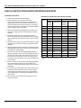
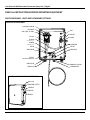
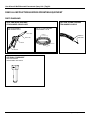
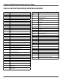
USER
MANUAL
MODEL NUMBER:
SP-WC
AND RELATED UNITS
Wall Mounted Concentrate Spray
Unit
English (Original Instructions)
User Manual: Wall Mounted Concentrate Spray Unit | English
READ ALL INSTRUCTIONS BEFORE OPERATING EQUIPMENT
WARNING
OPTIONS:
Pump Seal Material
Santoprene (standard)
SP-WC
Viton (V)
Kalrez (K)
Read this manual completely and understand the
machine before operating or servicing it.
• Read all instructions before installing or operating unit.
• Always wear appropriate personal protective equipment
(PPE) when operating or servicing unit.
• Always follow all chemical safety precautions and
handling instructions provided by the chemical
manufacturer and Material Safety Data Sheet (MSDS).
Add bold option codes to item number as shown. For standard
options, no option code is needed.
Examples:
• SP-WC (standard unit with Santoprene pump seals)
• SP-WCV (unit with Viton pump seals)
• If this unit is modified or serviced with parts not listed in
this manual, the unit may not operate correctly.
• Never point the discharge wand at yourself, another
person, or any object you do not want covered in
chemical.
• Always depressurize unit after use (as described in the
After Use Instructions). Always store unit depressurized,
with the discharge valve in the closed position.
• Do not exceed an incoming air pressure of 100 psi (7
bar).
• Do not exceed a fluid temperature of 100˚F (37˚C).
• Always flush the unit with fresh water for 2-4 minutes
when switching from an alkaline to an acid or an acid to
an alkaline.
• Only use clean and dry air. Air must be filtered and free
of moisture or pump life will be diminished. If needed,
install an air dryer before unit.
• Do not use an air lubricator before the unit.
• Never use unit with hydrocarbons or flammable
products.
PROTECT THE ENVIRONMENT
Please dispose of packaging materials, old machine
components, and hazardous fluids in an environmentally safe
way according to local waste disposal regulations.
Always remember to recycle.
*Specifications and parts are subject to change without notice.
Model Number: SP-WC AND RELATED UNITS
Page 2 of 8 | 09032014
User Manual: Wall Mounted Concentrate Spray Unit | English
READ ALL INSTRUCTIONS BEFORE OPERATING EQUIPMENT
REQUIREMENTS
Compressed air requirements
40-80 psi (3-5 bar) with 2 cfm (28.3 l/min)
Water requirements
10-100 psi (0.69-6.9 bar)
Backflow prevention is required – consult local plumbing ordinances for more information
Liquid temperature range
40-100˚F (4.4-37˚C)
Chemical compatibility
Chemical products used with this equipment must be formulated for this type of application and
compatible with unit materials and pump seals. For more information on chemical compatibility,
consult the manufacturer or MSDS for your product or contact our customer service department.
SPECIFICATIONS
Power type
Compressed air
Chemical pickup type
Draws from concentrated product
Dilution ratio range (water:chemical)*
34:1 to 640:1 with ST2520 fan tip;
24:1 to 640:1 with ST2550 fan tip
Number of products unit can draw from
One product
Suction line length/diameter
8 ft. (2.4 m) clear hose with 1/4 in. (6.4 mm) inside diameter
Discharge hose diameter/length
50 ft. (15 m) hose, with 1/2 in. (12.7 mm) inside diameter
Discharge wand/tip type
Polypropylene trigger handle with 25˚ fan tip
Output distance
10-12 ft. (3.0-3.7 m)
Output volume
2 gal/min (7.6 l/min) of liquid with ST2520 fan tip;
4-5 gal/min (15.1-18.9 gal/min) of liquid with ST2550 fan tip
Flow rate*
2 gal/min (7.6 l/min) with ST2520 fan tip;
4-5 gal/min (15.1-18.9 l/min) with ST2550 fan tip
Pump seals
Santoprene, Viton, or Kalrez
*Dilution rates and flow rates given are based on chemical with viscosity of water and factory air pressure settings.
Model Number: SP-WC AND RELATED UNITS
Page 3 of 8 | 09032014
User Manual: Wall Mounted Concentrate Spray Unit | English
READ ALL INSTRUCTIONS BEFORE OPERATING EQUIPMENT
Installation Instructions:
1. Remove all components from packaging.
2. Select desired area to mount the control box.
Note: We recommend mounting the control box at a
height of 6 feet or less. The chemical suction lines must
reach the bottom of the chemical container. The bottom
of the chemical container should not be positioned higher
than the bottom of the control box.
3. Attach the control box mounting feet to the back of the
control box, using the four screws provided in the parts
package.
4. Mount the control box to the wall using four of the
screws and plastic anchors provided in the parts package.
Note: To drill holes for the plastic anchors, use a 5/16 inch
drill bit.
5. Mount the hose hanger in a convenient location using the
remaining two screws and anchors provided in the parts
package.
6. Attach the discharge hose assembly to the discharge hose
barb (HBSS1212) and secure it with the larger hose clamp
provided in the parts package.
7. Connect the air inlet hose barb (HBSS1438) provided in
the parts package to the air inlet valve (BVB14) located on
the side of the control box. Then attach a 3/8 inch I.D. air
line from your air compressor to the air inlet hose barb,
and secure it with the smaller hose clamp provided in the
parts package.
METERING TIP COLOR CHART FOR SANITIZE FUNCTION
Metering
tip color
WITH ST2520 FAN TIP
WITH ST2550 FAN TIP
Ounces of
chemical
per gallon
of water*
Dilution ratio
(water:chemical)*
Ounces of
chemical
per gallon
of water*
Dilution ratio
(water:chemical)*
Copper
0.20
640:1
0.20
640:1
Pumpkin
0.30
427:1
0.30
427:1
Burgundy
0.40
320:1
0.40
320:1
Lime
0.41
312:1
0.41
312:1
Tan
0.42
305:1
0.42
305:1
Orange
0.54
237:1
0.67
191:1
Turquoise
0.61
209:1
0.72
177:1
Pink
1.01
127:1
1.18
108:1
Light blue
1.28
106:1
1.42
90:1
Brown
1.35
95:1
1.52
84:1
Red
1.82
70:1
2.7
47:1
White
1.89
67:1
2.8
46:1
Green
2.09
61:1
3.0
43:1
Blue
2.70
47:1
3.31
38:1
Yellow
3.71
34:1
5.2
24:1
No tip
7.37
17:1
13.5
10:1
*Injection rates will vary based on chemical viscosity, air pressure, and many
other factors. We recommend testing unit output to verify injection rate prior
to use.
8. Connect a water line to the water inlet fitting (SNB34GH).
Note: A back-flow preventer must be installed in the
water line – check local plumbing codes to ensure proper
installation.
9. Insert the proper metering tips and connect the chemical
intake lines to the inlet barbs. Note: Use the included
metering tip color charts to determine the appropriate
metering tip based on the product and dilution rate you
will be using.
10.Place the other end of each chemical intake line into a
chemical container.
Model Number: SP-WC AND RELATED UNITS
Page 4 of 8 | 09032014
User Manual: Wall Mounted Concentrate Spray Unit | English
READ ALL INSTRUCTIONS BEFORE OPERATING EQUIPMENT
Operation Instructions:
1. Follow all instructions from chemical manufacturer.
2. With the discharge valve (PSG12) in the closed position,
open the air inlet valves(BVB14).
3. Point the spray discharge wand in a safe direction and
open the discharge valve (PSG12) to begin spraying. The
discharge valve (PSG12) should be completely open while
spraying.
4. To stop spraying, close the discharge valve (PSG12).
After Use Instructions:
1. Place the chemical suction line into a container of water.
2. With the unit running, open the discharge valve (PSG12),
and allow the unit to be flushed with fresh water for
approximately 2-4 minutes or until all chemical has been
discharged from the unit.
3. Shut off the air supply to the unit by closing the air inlet
valve (BVB14).
4. Shut off the water supply to the unit.
5. Open the discharge valve (PSG12) to relieve any pressure
remaining in the unit.
6. Close the discharge valve (PSG12) after all pressure has
been relieved from the unit. Store the unit with the
discharge valve (PSG12) in the closed position.
Maintenance Instructions:
To keep the unit operating properly, periodically perform the
following maintenance procedures:
Note: Before performing any maintenance, disconnect the unit
from the compressed air and water supply and depressurize it as
described in the After Use Instructions.
• Drain the air compressor tank on a regular basis to help
extend pump life. An air source with a high moisture
content will accelerate pump wear. Note: If the air source
has a high moisture content, you may wish to install a
water separator (WS-20CFM) before the unit.
Troubleshooting Instructions:
• Check to ensure that the discharge hose is uncoiled
properly, and that there are no kinks that could obstruct
fluid flow.
• Check the air regulator bowl and air filter for debris such
as water, oil, or rust particles. Clean by unthreading the air
regulator bowl from the air regulator (R25).
• If air passes through the pump (P56/P56K/P56V) without
cycling, the pump needs to be replaced.
• Check for proper air pressure on the air gauge (AG100).
The air regulator (R25) is factory set at 50 psi (3.4 bar).
Operating range is 40-80 psi (3-5 bar) with 5-10 cfm
(141.6-283.3 l/min).
• If the unit operates at a reduced pressure:
oo Check the air compressor supplying the unit. If the
pressure is less than 40 psi (2.8 bar), turn the unit off
until the compressor can catch up.
oo If the air supply is 50 psi (3.4 bar) or above, check the
air gauge (AG100), which should read near 50 psi (3.4
bar). If the air gauge reads more or less than 50 psi
(3.4 bar), adjust the pressure by turning the knob on
the top of the air regulator (R25).
• Check the chemical metering tips, intake lines and
strainers for debris or damage. Clean or replace as
needed. To prevent damage to the unit, strainers must
always be used.
• Inspect the pump (P56/P56K/P56V) for wear and leaks.
• Inspect all hoses for leaks or excessive wear. Make sure all
hose clamps are in good condition and properly secured.
• Replace the filter located within the air regulator (R25) as
needed. Clean by unthreading the air regulator bowl from
the air regulator (R25).
• Check the chemical metering tips, intake lines and
strainers for debris and clean as needed.
Model Number: SP-WC AND RELATED UNITS
Page 5 of 8 | 09032014
User Manual: Wall Mounted Concentrate Spray Unit | English
READ ALL INSTRUCTIONS BEFORE OPERATING EQUIPMENT
PARTS DIAGRAMS - UNITS WITH STANDARD FITTINGS
CONTROL BOX ASSEMBLY
P56-BRKT-SCREW
P56-BRKT
P56, P56K, or P56V
R25
AG100
EC14-2
H14B-H
SSA14
(Available per .)
H38B-H
(Available per .)
SSC38
HBELF3838
HHPB3438
PEL34F
WR15G34
P203CT
(Thread metering p here)
HBFSS1238
HBSS1212
SNB34GH, SA12B
HHSB34GH12
CONTROL BOX ASSEMBLY OUTSIDE VIEW
PBFT-PP
PB16138-LATCH
FWLG14
SN1414
BVB14
Model Number: SP-WC AND RELATED UNITS
Page 6 of 8 | 09032014
User Manual: Wall Mounted Concentrate Spray Unit | English
READ ALL INSTRUCTIONS BEFORE OPERATING EQUIPMENT
PARTS DIAGRAMS
HOSE AND WAND ASSEMBLY
ITEM NUMBER: SGA12-HA50
ANTI-KINK SPRING ASSEMBLY
ITEM NUMBER: AKSS12
SPRAY GUN ASSEMBLY
ITEM NUMBER: SGA12
50 ft (15 m) HOSE ASSEMBLY
ITEM NUMBER: H12-50
ST2550
H12B-H
AKSS12-P
(Available per ft.)
PW124-120
AKSS-HPC
PSG12
HBSS1212
SSC12
HBSS1212
OPTIONAL COMPONENT
WATER SEPARATOR
ITEM NUMBER: WS-20CFM
Model Number: SP-WC AND RELATED UNITS
Page 7 of 8 | 09032014
User Manual: Wall Mounted Concentrate Spray Unit | English
READ ALL INSTRUCTIONS BEFORE OPERATING EQUIPMENT
ITEM NUMBER
DESCRIPTION
ITEM NUMBER
DESCRIPTION
AG100
1.5 INCH DRY MODEL 20 DUAL SCALE GAUGE
LATCH FOR PB16138
AKSS12-P
SS ANTI-KINK SPRING FOR 1.2 INCH HOSE
PB16138LATCH
AKSS-HPC
ANTI-KINK STAINLESS STEEL HITCH PIN CLIP
PB16138-PIN
STAINLESS STEEL HINGE PIN FOR CONTROL BOX PB16138 1/8 x 4 3/4 x 1/2inches
BVB14
AIR INLET VALVE - VA BRS 025-4F4F-BT, NICKEL
PBFT-PP
DEMA-MTKUL
DEMA - METERING TIP KIT - ULTRA LEAN FOR P203CT
MOUNTING FEET FOR POLYBOX - PB16138 POLYPROPYLENE
EC14-2
OETIKER CLAMP 13.8
PEL34F
3/4in FEMALE POLY PIPE ELBOW 90
F12SS
STAINLESS .875 ID FERRULE FOR 1/2 INCH HOSE
PL16138
FWLG14
.569 ID X 1.28 OD X .08 THICK FLAT WASHER SS 18-8
CONTROL BOX LID - POLYPROPYLENE - 16x13x8 - HINGED
LOCKABLE LID
FWP12
7/8 ID X 1.5 OD X 0.05 THK SSFW
PSG12
1/2 IN POLY SPRAY GUN WITH O-RING AND GRAY HANDLE
& 316SS
FWP78
7/8in BY .137 BY 1 1/4in FLATWASHER 18-8 PLN
H14B-H
1/4 INCH BLUE GOODYEAR HORIZON HOSE - Available per ft.
H12B-H
1/2 INCH BLUE GOODYEAR HORIZON HOSE - Available per ft.
H38B-H
3/8 INCH BLUE GOODYEAR HORIZON HOSE - Available per ft.
HBELF3838
HOSE BARB ELBOW 3/8” BY FPT 3/8”
HBFSS1238
HOSE BARB 3/8 X FEMALE PIPE THREAD 1/2 IN STAINLESS
STEEL
S1034FHL
10 X 3/4 PHIL FLAT HI-LO THRD SCREW 18-8
HBSS1212
STAINLESS HOSE BARB 1/2 X 1/2
SA12B
GARDEN HOSE SWIVEL ADAPTER X 1/2 MPT
HBSS1438
STAINLESS HOSE BARB 1/4 MPT X 3/8 INCH BARB
SN1414
STAINLESS 1/4MPT X 1/4MPT NIPPLE
HBSSEL1814
304 STAINLESS ELBOW 1/8 INCH NPT X 1/4 INCH HOSE BARB
SNB34GH
BRASS 3/4 GH SWIVEL NUT
HHPB3438
HEX HEAD POLY REDUCER BUSHING 3/4in X 3/8in
SSA12
STAINLESS MALE/FEMALE S.S. ADAPTOR 1/2in X 1/2in
HHSB34GH12
STAINLESS HEX HEAD BUSHING 3/4in MGH BY 1/2 FPT
SSA14
SS304 MALE/FEMALE ADAPTOR 1/4 NPT X 1/4 NPT
P14
COUNTERSUNK PLUG-HEXAGON 1/4
SSC12
WORM GEAR CLAMP, S/S (.31-.91)
P203CT
PLASTIC INJECTOR KIT INCLUDES INJECTOR - INTAKE HOSE FOOT STRAINER AND WEIGHT - TIP KIT
SSC38
WORM GEAR CLAMP, S/S (.25-.63)
P56
5700 PUMP WITH SANTOPRENE SEALS - INCLUDES HOSE
BARBS, AIR FITTING, AND AIR PORT
SSHH-F
S.S. LASER CUT HOSE HANGER - FLAT STOCK
ST2520
VEEJET NOZZLE - STAINLESS STEEL 2520
P56K
5700 PUMP WITH KALREZ SEALS - INCLUDES HOSE BARBS,
AIR FITTING, AND AIR PORT
ST2550
VEEJET NOZZLE, S.S. 2550
STR34
1in SEAL/STRAINER FOR 3/4 GH FITTINGS
P56V
5700 PUMP WITH VITON SEALS - INCLUDES HOSE BARBS,
AIR FITTING, AND AIR PORT
WMS14
14 X 1 1/4 HEX W/H SMS SLOTT, S/S
WMS14A
5/16 X 1 1/2 STRAIGHT PLASTIC ANCHOR
WR15G34
WATER PRESSURE REGULATOR - 3/4in FGH BY 3/4in MPT
Body ABS, internal parts, SS, PP and Santo
WS-20CFM
TSUNAMI WATER SEPARATOR/AIR DRYER 20 CFM
20756103B
Polypro G57 Air Port x HB Straight, w/ Viton o-ring
HB14P
1/4in BRASS HB AIR FITTING /G57/P56 HB5638
HOSE BARB FOR P56 PUMP
HB5638K
HOSE BARB FOR P56K PUMP
HB5638V
HOSE BARB FOR P56V PUMP
P56-BRKT
PUMP BRACKET- STAINLESS STEEL
P56-BRKTSCREW
HI LO SCREW FOR RETAINING P56-BRKT
PB16138
POLYPROPYLENE CONTROL BOX - WORKING DIMS 16x13x8
- PUMP MOUNT
PB16138-GSKT
NEOPRENE GASKET 0.220 INCH ROUND CORD STOCK 61.125 INCHES
Model Number: SP-WC AND RELATED UNITS
PSGORV
PSG12 O RING
PW124-120
1/2in BLACK POLY PRO X 4in - SCH.120 - 1/2in MPTOE &
1/4in FPTOE
R25
AIR REGULATOR INCLUDES AIR FILTER AND BOWL
AFR25
AIR FILTER for R25
ABR25
METAL AIR BOWL for R25
Page 8 of 8 | 09032014