1
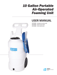
USER
MANUAL
MODEL NUMBER:
DS4
DS4K
DS4V
AND RELATED UNITS
Twin-Line Concentrate Doorway Foam
Unit
English (Original Instructions)
User Manual: Twin-Line Concentrate Doorway Foam Unit | English
READ ALL INSTRUCTIONS BEFORE OPERATING EQUIPMENT
WARNING
OPTIONS
Pump Seal Material
DS4
Santoprene (standard)
One (standard)
Viton (V)
Two (2)
Kalrez (K)
Read this manual completely and understand the
machine before operating or servicing it.
• Read all instructions before installing or operating unit.
• Always wear appropriate personal protective equipment
(PPE) when operating or servicing unit.
• Always follow all chemical safety precautions and
handling instructions provided by the chemical
manufacturer and Safety Data Sheet (SDS).
Number of Nozzles
-
Three (3)
Add bold option codes to item number as shown. For standard
options, no option code is needed.
Examples:
• DS4 (standard unit with Santoprene pump seals and one
nozzle)
• DS4-2 (unit with Santoprene pump seals and two
nozzles)
• DS4V-2 (unit with Viton pump seals and two nozzles)
• If this unit is modified or serviced with parts not listed in
this manual, the unit may not operate correctly.
• Do not exceed an incoming air pressure of 100 psi (7
bar).
• Do not exceed a fluid temperature of 100˚F (37˚C).
• Always flush the unit with fresh water for 5 minutes
when switching from an alkaline to an acid or an acid to
an alkaline.
• Never use unit with hydrocarbons or flammable
products.
• Only use clean and dry air. Air must be filtered and free
of moisture or pump life will be diminished. If needed,
install an air dryer before unit.
• Do not use an air lubricator before the unit.
• Never use unit if it is damaged or leaking.
• Disconnect unit from electrical power source before
servicing.
PROTECT THE ENVIRONMENT
Please dispose of packaging materials, old machine
components, and hazardous fluids in an environmentally safe
way according to local waste disposal regulations.
Always remember to recycle.
*Specifications and parts are subject to change without notice.
Model No.: DS4, DS4K, DS4V
Page 2 of 10 | 07292015
User Manual: Twin-Line Concentrate Doorway Foam Unit | English
READ ALL INSTRUCTIONS BEFORE OPERATING EQUIPMENT
System Overview:
One control box can support up to three nozzle assemblies. The combined distance between the control box and the nozzle(s) must equal 100 ft. (30.5 m) or less. COMPLETE SYSTEMS
Item Number:
DS4
DS4-2
DS4-3
Includes:
Control box and one nozzle
assembly
Control box and two nozzle
assemblies
Control box and three nozzle
assemblies
Spray tip:
ST80200
ST80100
ST8060-1/2
Foam pattern:
Up to 9x5 ft. (2.7x1.5 m)
Up to 8x4 ft. (2.4x1.2 m) at each
nozzle
Up to 6x3 ft. (1.8x0.9 m) at each
nozzle
Tubing (H12CP)
included:
50 ft. (15.2 m)
100 ft. (30.4 m)
150 ft. (45.7 m)
3
5
Tee fittings
2
(QFT12) included:
REPLACEMENT NOZZLE ASSEMBLIES
Item Number:
GK7T
GK7T-2
GK7T-3
Includes:
One nozzle assembly with ST80200
spray tip
One nozzle assembly with ST80100
spray tip, plus one extra ST80100
spray tip
One nozzle assembly with ST8060-1/2 spray tip
Intended use:
Replacement nozzle for a 1-nozzle
system
Replacement nozzle for a 2-nozzle
system, or conversion kit to turn
an existing 1-nozzle system into a
2-nozzle system
Replacement nozzle for a 3-nozzle
system
Spray tip:
ST80200
ST80100 (also includes an extra tip
to retrofit an existing nozzle)
ST8060-1/2
Tubing (H12CP)
included:
50 ft. (15.2 m)
50 ft. (15.2 m)
50 ft. (15.2 m)
2
2
Tee fittings
2
(QFT12) included:
Model No.: DS4, DS4K, DS4V
Page 3 of 10 | 07292015
User Manual: Twin-Line Concentrate Doorway Foam Unit | English
READ ALL INSTRUCTIONS BEFORE OPERATING EQUIPMENT
REQUIREMENTS
Compressed air requirements
40-80 psi (3-5 bar) with 5-10 cfm (141.6-283.3 l/min)
Water requirements
10-100 psi (0.69-6.9 bar)
Backflow prevention is required – consult local plumbing ordinances for more information.
Liquid temperature range
40-100˚F (4.4-37˚C)
Electrical requirements
120 VAC at 60 Hz, 2 amps (GFCI protected outlet)
Operating voltage
120 VAC
Chemical compatibility
Chemical products used with this equipment must be formulated for this type of application
and compatible with unit materials and pump seals. For more information on chemical
compatibility, consult the manufacturer or SDS for your product or contact our customer
service department.
SPECIFICATIONS
Power type
Compressed air, electricity
Chemical pickup type
Draws from concentrated product
Dilution ratio range
(water:chemical)*
38:1 to 183:1
Number of products unit can
One product
draw from (and whether it draws
simultaneously or one at a time)
Suction line length/diameter
8 ft. (2.4 m) clear hose with 1/4 in. (6.4 mm) inside diameter
Flow rate*
2 gal/min (7.6 l/min)
Pump seals
Santoprene, Viton, or Kalrez
Timer operation type
Repeat cycle
Coverage area
With one nozzle: up to 9x5 ft. (2.7x1.5 m);
With two nozzles: up to 8x4 ft. (2.4x1.2 m) at each nozzle;
With three nozzles: up to 6x3 ft. (1.8x0.9 m) at each nozzle
Fan tip
With one nozzle: ST80200;
With two nozzles: ST80100;
With three nozzles: ST8060-1/2
Nozzle type
Twin-line stainless steel nozzle assembly (GK7T)
Number of nozzles
One control box can support up to three nozzle assemblies
Distance from nozzles to control
box
The combined distance between the control box and the nozzle(s) must equal 100 ft. (30.5 m)
or less.
Tubing/fitting sizes
Designed for use with 1/2 in. (12.7 mm) outside diameter tubing between control box and
nozzle(s)
*Dilution rates and flow rates given are based on chemical with viscosity of water and factory air pressure settings.
Model No.: DS4, DS4K, DS4V
Page 4 of 10 | 07292015
User Manual: Twin-Line Concentrate Doorway Foam Unit | English
READ ALL INSTRUCTIONS BEFORE OPERATING EQUIPMENT
Installation Instructions:
1. Remove all components from packaging.
2. Select an area to mount the control box. Note: The control box should be mounted to a vertical
wall. We recommend mounting the control box at a
height of 6 feet or less. The chemical suction line must
reach the bottom of the chemical container. The bottom
of the chemical container should not be positioned higher
than the bottom of the control box.
3. Attach the control box mounting feet to the back of the
control box, using the four screws provided in the parts
package.
4. Mount the control box to the wall using four of the screws
and plastic anchors provided in the parts package. Note: To drill holes for the plastic anchors, use a 5/16
inch drill bit.
5. Mount the stainless steel nozzle assembly in the desired
location, using two stainless steel brackets (SSFTB) and
four of the screws and plastic anchors provided in the
parts package. Repeat as needed for multiple nozzles.
Note: The foam pattern dimensions provided in this
manual were measured with nozzle assemblies mounted
6 in. (15 cm) above the floor. 6. Run tubing from the solution outlet fitting on the control
box to the solution inlet fitting on the nozzle assembly. For multiple nozzles, run the tubing from the control box
into a tee fitting (QFT12), as shown in the diagram. Then,
run tubing from the tee fitting to the nozzle assemblies. For systems with three nozzles, use a second tee fitting to
split the line again.
7. Run tubing from the air outlet fitting on the control box to
the air inlet fitting on the nozzle assembly. For multiple
nozzles, split the line using one or more tee fittings
(QFT12), as described in step 6 and shown in the diagram.
Note: The air and solution lines must be routed to the
appropriate fittings (as labeled), or the foam quality of
the unit will be negatively impacted. Make sure to insert
the tubing all the way into the fittings to ensure proper
connection.
TEE FITTING (QFT12) DIAGRAM
Correct
Correct
OUT
OUT
Incorrect
Incorrect
OUT
OUT
IN IN
Connecting the inlet to the stem
of the tee creates even discharge
from each side
Model No.: DS4, DS4K, DS4V
IN IN
OUT
OUT
8. Connect the air inlet hose barb (HBSS1438) provided in
the parts package to the air inlet valve (BVB14) located on
the side of the control box. Then attach a 3/8 inch I.D. air
line from your air compressor to the air inlet hose barb,
and secure it with the smaller hose clamp provided in the
parts package.
9. Connect a water line to the unit. The control box has a 1/2
inch FPT water inlet fitting (SSA12).
Note: A back-flow preventer must be installed in the
water line – check local plumbing codes to ensure proper
installation.
10.Open the cover of the control box. Insert the proper
metering tip and connect the chemical intake line to the
injector inlet barb.
Note: Use the included metering tip color chart to
determine the appropriate metering tip based on the
product and dilution rate you will be using.
INJECTION RATES
METERING TIP COLOR
OZ./GAL.
RATIO*
TAN
0.70
183-1
ORANGE
0.90
142-1
TURQUOISE
1.15
111-1
PINK
1.55
83-1
LIGHT BLUE
1.80
71-1
BROWN
1.85
69-1
RED
2.65
48-1
WHITE
3.40
38-1
** Injection rates will vary based on chemical
viscosity, air pressure, and many other factors. We
recommend testing unit output to verify injection
rate prior to use.
11.Place the other end of the chemical intake line into a
chemical container.
Note: The chemical suction line must reach the bottom of
the chemical container. A strainer must be used on the
chemical intake line.
12.Set the timer for the desired on time and off time, as
described in the timer adjustment instructions.
OUT
OUT
Connecting the inlet to one
side of the tee creates uneven
discharge
Page 5 of 10 | 07292015
User Manual: Twin-Line Concentrate Doorway Foam Unit | English
READ ALL INSTRUCTIONS BEFORE OPERATING EQUIPMENT
TIMER ADJUSTMENT INSTRUCTIONS
RED = OUTPUT OFF
COMBINE SWITCHES
FOR TOTAL TIME
ON TIME
FOAM-IT
PN: TR120DS-A
LOAD OUT
3
120 VAC
INPUT
MIN
OFF TIME
-
120 VAC IN
+
OUT TO
SOLENOIDS
SEC
The TR120DS-A is an adjustable repeat cycle timer with
operating first. ON and OFF times can range from 1 sec
2. Open the compressed air inlet valve (BVB14).
1
2
4
8
ON
16
32
64
128
256
4. While
the unit
is running
and discharging
product,
adjust
2: The
next
9 dip switches
will be
used to
control the to
the needle
(NV14Y),
left isvalve
inactive
andlocated
to theinside
rightthe
is control
active.box,
Combine the
as needed to regulate the wetness or dryness of the foam
active
following
the dip
stepsswitches
below: to achive the desired time.
a.
Close needle
(NV14Y)
completely
in clockwise
3: Repeat
thevalve
above
steps
for the OFF
time setting.
direction.
b. Open needle valve (NV14Y) in counter-clockwise
direction 2 complete turns.
c. Continue to open needle valve in ¼ turn increments,
allowing 30 seconds between adjustments, until
desired consistency of foam is achieved.
2
GREEN = OUTPUT ON
1
MIN
1.TIMER
Verify thatADJUSTMENT
the unit is connectedINSTRUCTIONS:
to compressed air, water,
power, and chemical.
1
2
4
8
ON
16
32
64
128
256
OFF
SEC
Operation Instructions:
OFF
The TR120DS-A is an adjustable repeat cycle timer with the ON time
operating first. ON and OFF times can range from 1 second to 511
minutes.
To set the timer:
1. Starting with the ON time, move the top dip switch to the left
for SEC (seconds) or to the right for MIN (minutes) to select
the desired time interval.
2. The next 9 dip switches will be used to control the total
active time. To the left is inactive and to the right is active.
Combine the numbers next to the active dip switches to
achive the desired time.
3. Repeat the above steps for the OFF time setting.
3. To activate the unit, turn the power switch ON. The
1:will
Starting
with the
ONthe
time,
move
top dip switch t
unit
begin cycling
through
on time
andthe
off time
(seconds)
to the
right for
MIN
(minutes)
to set the
intervals
set on theor
timer,
beginning
with
the on
time.
5. To deactivate the unit, turn the power switch OFF.
13.With the power switch in the OFF position, plug the unit
into a GFCI protected 120 VAC power outlet.
Model No.: DS4, DS4K, DS4V
Page 6 of 10 | 07292015
User Manual: Twin-Line Concentrate Doorway Foam Unit | English
READ ALL INSTRUCTIONS BEFORE OPERATING EQUIPMENT
Maintenance Instructions:
To keep your foam unit operating properly, periodically perform
the following maintenance procedures:
Note: Before performing any maintenance, ensure that the
unit has been turned OFF, unplugged from the electrical power
source, and disconnected from the air/water supply.
• Inspect the pump (P56/P56K/P56V) for wear and leaks.
• Inspect all hoses for leaks or excessive wear. Make sure all
hose clamps and push-fittings are in good condition and
properly secured.
• Replace the filter (AFR25) located within the air regulator
(R25) as needed. Clean by unthreading the air regulator
bowl (ABR25) from the air regulator (R25).
• Check the chemical metering tip, suction line and strainer
for debris and clean as needed.
• Drain your air compressor tank on a regular basis to help
extend pump life. An air source with a high moisture
content will accelerate pump wear. Note: If your air
source has a high moisture content, you may wish to
install a water separator (item number WS-20CFM, sold
separately) before the unit.
Troubleshooting Instructions:
• Check the air regulator bowl (ABR25) and air filter (AFR25)
for debris such as water, oil, or rust particles. Clean by
unthreading the air regulator bowl (ABR25) from the air
regulator (R25).
• If the needle valve (NV14Y) is open too far, the pump
(P56/P56K/P56V) may cycle improperly due to lack of
air pressure. If this occurs, close and readjust the needle
valve (NV14Y) as described in Operation Instruction #2.
• Make sure proper foaming chemical and concentration
are being used.
• If air passes through the pump (P56/P56K/P56V) without
cycling, the pump needs to be replaced.
• If solution backs up into the air regulator bowl (ABR25),
the check valve (CV38) needs to be replaced.
• If foam comes out wet, no matter where the needle valve
(NV14Y) is positioned, the check valve (CV38) may need to
be replaced.
• Check for proper air pressure on the air gauge (AG100).
The air regulator (R25) is factory set at 50 psi (3.4 bar).
Operating range is 40 to 80 psi (3 to 5 bar) with 3.5 to 8
CFM (99 to 226.5 l/min).
• If the unit operates at a reduced pressure:
oo Check the air compressor supplying the unit. If the
pressure is less than 40 psi, turn the unit off until the
compressor can catch up.
oo If the air supply is 50 psi (3.4 bar) or above, check the
air gauge (AG100), which should read near 50 psi (3.4
bar). If the air gauge reads more or less than 50 psi
(3.4 bar), adjust the pressure by turning the knob on
the top of the air regulator (R25).
• Check the chemical metering tip, suction line and strainer
for debris or damage. Clean or replace as needed. To
prevent damage to the unit, the strainer must always be
used.
• Check for proper water pressure on the water pressure
gauge (WRG14). To check the pressure:
oo Activate the unit and allow it to run through an on
time cycle.
oo During the subsequent off time cycle, check the water
pressure gauge (WRG14). The pressure should read
20 psi (1.4 bar) during the off time cycle or when
deadheaded.
oo If necessary, adjust the water regulator using the
flathead screw on the regulator body. The water
pressure should be set at 20 psi (1.4 bar) when
deadheaded. Setting the pressure higher or lower
may damage the unit or cause it to malfunction.
Model No.: DS4, DS4K, DS4V
Page 7 of 10 | 07292015
User Manual: Twin-Line Concentrate Doorway Foam Unit | English
READ ALL INSTRUCTIONS BEFORE OPERATING EQUIPMENT
CONTROL BOX ASSEMBLY
PB16138-LATCH
TS2PLATE
TS2
TSBT12
CC8463
CC3224
BVB14
WR1A
SN1414
PBFT-PP
P56-BRKT
TR120DS-A
P56-BRKT-SCREW
R25
P56, P56K or P56V
TS2
HBSSEL1438
PN1238
ACV1D38
CV38
SN1414
AG100
ACV1
SN1414
NV14Y
HBELF3838
P203CT
HBF3812
SSE12
WRG14
WR12SS
FWP78
SSA12
R25DT
QF1212
Model No.: DS4, DS4K, DS4V
Page 8 of 10 | 07292015
User Manual: Twin-Line Concentrate Doorway Foam Unit | English
READ ALL INSTRUCTIONS BEFORE OPERATING EQUIPMENT
NOZZLE ASSEMBLY
QF1212
CV12F7-AP
SN1212
SSE12
QF1212
SST12
SN1212
HHSB11412
SSFT
NOZZLE ASSEMBLY DETAIL
This unit includes an adjustable ball-type nozzle that
may be installed to hold the spray tip as shown.
HHSB11412
SSE12
ST80200, ST80100 or ST8060-1/2
(Spray tip size varies based on number of
nozzle assemblies used - see specifcations
chart for more information.)
ABTN12
ABTNTB12
PARTS INFORMATION - LEGACY/DISCONTINUED COMPONENTS
LEGACY WATER REGULATOR ASSEMBLY
LEGACY PARTS DIAGRAM
PN3834
PEL34F
WR15G34
HHSB34GH12
LEGACY PARTS LIST
ITEM NUMBER DESCRIPTION
HHSB34GH12
STAINLESS HEX HEAD BUSHING 3/4in MGH BY 1/2 FPT
PEL34F
3/4in FEMALE POLY PIPE ELBOW 90
PN3834
POLY REDUCER NIPPLE 3/8in MPT X 3/4in MPT
WR15G34
WATER PRESSURE REGULATOR - 3/4in FGH BY 3/4in
MPT Body ABS, internal parts, SS, PP and Santo
Conversion kit to upgrade to current water inlet: CK-WR12SS.
SSA12
Model No.: DS4, DS4K, DS4V
Page 9 of 10 | 07292015
User Manual: Twin-Line Concentrate Doorway Foam Unit | English
READ ALL INSTRUCTIONS BEFORE OPERATING EQUIPMENT
ITEM NUMBER
DESCRIPTION
ABTN12
ADJUSTABLE BALL-TYPE NOZZLE 1/2in NPT
ABTNTB12
1/2in THREADED BALL FOR ABTN12
ACV1
MAC VALVE 1/4in 110VAC
ACV1D38
110VAC SOLENOID VALVE 3/8in
AG100
1.5 INCH DRY MODEL 20 DUAL SCALE GAUGE
B10321
PB16138
POLYPROPYLENE CONTROL BOX - WORKING DIMS 16x13x8
- PUMP MOUNT
PB16138-GSKT
NEOPRENE GASKET 0.220 INCH ROUND CORD STOCK 61.125 INCHES
PB16138LATCH
LATCH FOR PB16138
PB16138-PIN
STAINLESS STEEL HINGE PIN FOR CONTROL BOX PB16138
10-32 X 1 PHIL TRUSS MACH SCR 18-8
PBFT-PP
B10321.25
10-32 X 1 1/4 PHIL TRUSS MACH 18-8
MOUNTING FEET FOR POLYBOX - PB16138 POLYPROPYLENE
BVB14
AIR INLET VALVE - VA BRS 025-4F4F-BT, NICKEL
PL16138
POLYPROPYLENE - 16x13x8 - HINGED LOCKABLE LID
CC3224
LTC BLACK 1/2 NPT
PN1238
1/2in MPT X 3/8 in MPT POLY NIPPLE
CC8463
1/2in NPT BLACK LOCKNUT
QF1212
MALE CON. 1/2in TUBE X 1/2in MPT - POLYPROPYLENE
CV12F7-AP
1/2 CHECK VALVE 7 LB SPRING - HASTELLOY SPRING - EP
SEALS - ACID PROOF - BLK/WHT CHK
QFT12
UNION TEE 1/2in TUBE - POLYPROPYLENE
R25
CV38
PVC CHECK VALVE 3/8 BARBS - SS SPRING
AIR REGULATOR - 1/4fpt TWO PORT 1/8fpt TWO PORT INCLUDES FILTER AND BOWL
AFR25
EC14-2
OETIKER CLAMP 13.8
AIR FILTER for R25
ABR25
FWLG14
.569 ID X 1.28 OD X .08 THICK FLAT WASHER SS 18-8
METAL AIR BOWL for R25
FWP12
7/8 ID X 1.5 OD X 0.05 THK SSFW
FWP78
7/8in BY .137 BY 1 1/4in FLATWASHER 18-8 PLN
H12CP
1/2IN OD POLYETHYLENE TUBING - NATURAL - Available
per ft.
H14B-H
1/4 INCH BLUE HOSE - Available per ft.
H38B-H
3/8 INCH BLUE HOSE - Available per ft.
HBELF3838
HOSE BARB ELBOW 3/8” BY FPT 3/8”
HBF3812
HOSE BARB 3/8 X FEMALE PIPE THREAD 1/2 IN
HBSS1438
STAINLESS HOSE BARB 1/4 MPT X 3/8 BARB
HBSSEL1438
STAINLESS HOSE BARB ELBOW 1/4 NPT X 3/8 HOSE BARB
HBSSEL1814
304 STAINLESS ELBOW 1/8 INCH NPT X 1/4 INCH HOSE BARB
HHSB11412
HEX HEAD STAINLESS BUSHING 1 1/4IN BY 12IN
NV14Y
FLOW CONTROL VALVE - INCLUDES BLACK KNOB
NV14Y-HNDL
BLACK KNOB FOR NEEDLE VALVE - 2839-1/4
R25DT
CLEAR TUBING FOR R25 DRAIN
S1034FHL
10 X 3/4 PHIL FLAT HI-LO THRD SCREW 18-8
SN1212
1/2in HEX STAINLESS STEEL NIPPLE
SN1414
STAINLESS 1/4MPT X 1/4MPT NIPPLE
SSA12
STAINLESS MALE/FEMALE S.S. ADAPTOR 1/2in X 1/2in
SSC38
WORM GEAR CLAMP, S/S (.25-.63)
SSE12
STREET ELBOW 1/2in - 316 S.S.
SSFT
Stainless Steel Foam Tube 1 1/2in @ 8INCH CUT
SSFTB
STAINLESS STEEL FOAM TUBE BRACKET
SSMESH
STAINLESS STEEL MESH
SSST
SCREEN DISC .687 DIA. 10 X 10 MESH @ .020 DIA
SST12
1/2in FPT 304 S.S. TEE
ST80100
VEEJET NOZZLE, 80100
ST80200
VEEJET NOZZLE, 80200
ST8060-1/2
1/2 INCH VEEJET NOZZLE, BRASS 8060
TR120DS-A
REPEAT CYCLE TIMER - ADJUSTABLE DIGI-SET - 120 VAC
P203CT
PLASTIC INJECTOR KIT INCLUDES INJECTOR - INTAKE HOSE FOOT STRAINER AND WEIGHT - TIP KIT
P56
5700 PUMP WITH SANTOPRENE SEALS - INCLUDES HOSE
BARBS, AIR FITTING, AND AIR PORT
TS2
TOGGLE SWITCH SPST
P56K
5700 PUMP WITH KALREZ SEALS - INCLUDES HOSE BARBS,
AIR FITTING, AND AIR PORT
TS2PLATE
ON/OFF SWITCH PLATE
TSBT12
TOGGLE SWITCH BOOT
P56V
5700 PUMP WITH VITON SEALS - INCLUDES HOSE BARBS,
AIR FITTING, AND AIR PORT
WCB14F
14-16 - 1/4 FEM INSULATED CONNECTOR
WCB14FY
10-12 - 1/4in FEMALE INSULATED CONNECTOR
WMS14
14 X 1 1/4 HEX W/H SMS SLOTT, S/S
WMS14A
5/16 X 1 1/2 STRAIGHT PLASTIC ANCHOR
WR12SS
WATER PRESSURE REGULATOR - STAINLESS STEEL - 1/2 INCH
FPT
20756103B
Polypro G57 Air Port x HB Straight, w/ Viton o-ring
HB14P
1/4in BRASS HB AIR FITTING /G57/P56 HB5638
HOSE BARB FOR P56 PUMP
HB5638K
HOSE BARB FOR P56K PUMP
HB5638V
HOSE BARB FOR P56V PUMP
WR1A
18/3 SJOOW 90 BLACK N.A. W/ 5-15P & 7in ROJ
P56-BRKT
PUMP BRACKET- STAINLESS STEEL
WRG14
WATER PRESSURE REGULATOR GAUGE FOR WR12SS
P56-BRKTSCREW
HI LO SCREW FOR RETAINING P56-BRKT
Model No.: DS4, DS4K, DS4V
Page 10 of 10 | 07292015