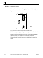
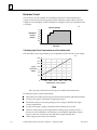
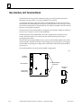
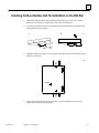
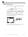
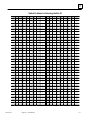
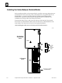
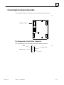
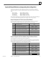
1
ÎÎ
GE Fanuc Automation
Programmable Control Products
t
Field Control
Distributed I/O and Control System
Profibus Bus Interface Unit
User’s Manual
GFK-1291A
September 1996
GFL–002
Warnings, Cautions, and Notes
as Used in this Publication
Warning
Warning notices are used in this publication to emphasize that
hazardous voltages, currents, temperatures, or other conditions that
could cause personal injury exist in this equipment or may be
associated with its use.
In situations where inattention could cause either personal injury or
damage to equipment, a Warning notice is used.
Caution
Caution notices are used where equipment might be damaged if care is
not taken.
Note
Notes merely call attention to information that is especially significant to
understanding and operating the equipment.
This document is based on information available at the time of its publication. While
efforts have been made to be accurate, the information contained herein does not
purport to cover all details or variations in hardware or software, nor to provide for
every possible contingency in connection with installation, operation, or maintenance.
Features may be described herein which are not present in all hardware and software
systems. GE Fanuc Automation assumes no obligation of notice to holders of this
document with respect to changes subsequently made.
GE Fanuc Automation makes no representation or warranty, expressed, implied, or
statutory with respect to, and assumes no responsibility for the accuracy, completeness,
sufficiency, or usefulness of the information contained herein. No warranties of
merchantability or fitness for purpose shall apply.
The following are trademarks of GE Fanuc Automation North America, Inc.
Alarm Master
CIMPLICITY
CIMPLICITY
PowerTRAC
CIMPLICITY 90–ADS
CIMSTAR
Field Control
GEnet
Genius
Genius PowerTRAC
Helpmate
Logicmaster
Modelmaster
ProLoop
PROMACRO
Series Five
Series 90
Series One
Series Six
Series Three
VuMaster
Workmaster
Copyright 1996 GE Fanuc Automation North America, Inc.
All Rights Reserved
Preface
Content of this Manual
t
This manual describes the Field Control Profibus Bus Interface Unit (IC670PBI001). It
explains operation of the Bus Interface Unit as a Profibus device.
t
Chapter 1. Introduction: Chapter 1 introduces Field Control modules, the Profibus Bus
Interface Unit (IC670PBI001), and other equipment that may be used with the Bus Interface
Unit.
Chapter 2. Installation: Chapter 2 describes installation procedures for the Bus Interface
Unit.
Chapter 3. Autoconfiguration: Chapter 3 explains the features of Autoconfiguration,
which automatically configures the operation of the I/O Station and enables it to start
exchanging I/O and diagnostics data with the master.
Chapter 4. Instructions for Using a Hand-held Programmer: Chapter 4 explains how to
use a Hand-held Programmer with a Profibus BIU.
Chapter 5. Operation: Chapter 5 is a general description of the operation of the Profibus
BIU.
Chapter 6. Communications: Chapter 6 explains how Profibus master devices
communicate with the Profibus Bus Interface Unit. The communications described in
this chapter are controlled by the master through the application program. Specific
Profibus system programming instructions are not included.
Related Publications
For more information, refer to these publications:
t
Field Control I/O Modules User’s Manual (GFK-0826). This book describes Field Control
I/O Modules and I/O Terminal Blocks and explains how to install them.
We Welcome Your Comments and Suggestions
At GE Fanuc automation, we strive to produce quality technical documentation. After
you have used this manual, please take a few moments to complete and return the
Reader ’s Comment Card located on the next page.
Jeanne Grimsby
Senior Technical Writer
GFK-1291A
Profibus Bus Interface Unit User’s Manual – September 1996
iii
iv
User’s Manual – September 1996
GFK-1291A
Contents
Chapter 1
Chapter 2
Chapter 3
GFK-1291A
Introduction . . . . . . . . . . . . . . . . . . . . . . . . . . . . . . . . . . . . . . . . . . . . . . . .
1-1
Overview . . . . . . . . . . . . . . . . . . . . . . . . . . . . . . . . . . . . . . . . . . . . . . . . . . . . . . .
1-1
Field Control Modules . . . . . . . . . . . . . . . . . . . . . . . . . . . . . . . . . . . . . . . . . . . . .
1-2
Locations for Field Control . . . . . . . . . . . . . . . . . . . . . . . . . . . . . . . . . . . . . . . . .
1-4
Field Control Environmental Specifications . . . . . . . . . . . . . . . . . . . . . . . . . . .
1-5
Profibus Bus Interface Unit . . . . . . . . . . . . . . . . . . . . . . . . . . . . . . . . . . . . . . . . .
1-6
Bus Interface Unit Terminal Block . . . . . . . . . . . . . . . . . . . . . . . . . . . . . . . . . . .
1-10
Bus Interface Unit Functional Specifications . . . . . . . . . . . . . . . . . . . . . . . . . .
1-11
Configuration . . . . . . . . . . . . . . . . . . . . . . . . . . . . . . . . . . . . . . . . . . . . . . . . . . . .
1-12
Hand-held Programmer . . . . . . . . . . . . . . . . . . . . . . . . . . . . . . . . . . . . . . . . . . .
1-12
Profibus . . . . . . . . . . . . . . . . . . . . . . . . . . . . . . . . . . . . . . . . . . . . . . . . . . . . . . . . .
1-13
Installation . . . . . . . . . . . . . . . . . . . . . . . . . . . . . . . . . . . . . . . . . . . . . . . . .
2-1
Preinstallation Check . . . . . . . . . . . . . . . . . . . . . . . . . . . . . . . . . . . . . . . . . . . . .
2-2
Static Protection . . . . . . . . . . . . . . . . . . . . . . . . . . . . . . . . . . . . . . . . . . . . . . . . . .
2-2
Conformance to Standards . . . . . . . . . . . . . . . . . . . . . . . . . . . . . . . . . . . . . . . . .
2-2
Removing the Bus Interface Unit from the Terminal Block . . . . . . . . . . . . .
2-3
Installing the DIN Rail . . . . . . . . . . . . . . . . . . . . . . . . . . . . . . . . . . . . . . . . . . . .
2-4
Installing the Bus Interface Unit Terminal Block on the DIN Rail . . . . . . . . .
2-5
Setting the BIU DIP Switches . . . . . . . . . . . . . . . . . . . . . . . . . . . . . . . . . . . . . . .
2-6
Installing the Cables Between Terminal Blocks . . . . . . . . . . . . . . . . . . . . . . .
2-8
Installing the Bus Interface Unit on the Terminal Block . . . . . . . . . . . . . . . . .
2-9
Removing the Bus Interface Unit from the Terminal Block . . . . . . . . . . . . . .
2-9
System Wiring Guidelines . . . . . . . . . . . . . . . . . . . . . . . . . . . . . . . . . . . . . . . . .
2-10
System Grounding . . . . . . . . . . . . . . . . . . . . . . . . . . . . . . . . . . . . . . . . . . . . . . . .
2-11
Power Wiring to the Bus Interface Unit . . . . . . . . . . . . . . . . . . . . . . . . . . . . . .
2-12
Connecting the Communications Bus . . . . . . . . . . . . . . . . . . . . . . . . . . . . . . . .
2-13
Bus Termination . . . . . . . . . . . . . . . . . . . . . . . . . . . . . . . . . . . . . . . . . . . . . . . . . .
2-15
Observing the LEDs . . . . . . . . . . . . . . . . . . . . . . . . . . . . . . . . . . . . . . . . . . . . . .
2-16
Removing/Replacing the Bus Interface Unit Fuse . . . . . . . . . . . . . . . . . . . . . .
2-17
Removing the Bus Interface Unit Terminal Block . . . . . . . . . . . . . . . . . . . . . .
2-18
Upgrading the BIU Firmware . . . . . . . . . . . . . . . . . . . . . . . . . . . . . . . . . . . . . .
2-19
Autoconfiguration . . . . . . . . . . . . . . . . . . . . . . . . . . . . . . . . . . . . . . . . . .
3-1
Description . . . . . . . . . . . . . . . . . . . . . . . . . . . . . . . . . . . . . . . . . . . . . . . . . . . . . .
3-2
Input and Output References Assigned by Autoconfiguration . . . . . . . . . . .
3-3
Hand-held Programmer Settings for Autoconfiguration . . . . . . . . . . . . . . . .
3-5
Autoconfiguration with a Hand-Held Programmer . . . . . . . . . . . . . . . . . . . .
3-5
Notes about Adding and Deleting Modules . . . . . . . . . . . . . . . . . . . . . . . . . . .
3-6
Profibus Bus Interface Unit User’s Manual – September 1996
v
Contents
Chapter 4
Chapter 5
Chapter 6
vi
Instructions for Using a Hand-held Programmer . . . . . . . . . . . . . . . .
4-1
Getting Started . . . . . . . . . . . . . . . . . . . . . . . . . . . . . . . . . . . . . . . . . . . . . . . . . . .
4-2
Displaying and Editing BIU Configuration Data . . . . . . . . . . . . . . . . . . . . . . .
4-4
Performing and Disabling Autoconfiguration . . . . . . . . . . . . . . . . . . . . . . . . .
4-6
Enabling or Disabling I/O Scanning . . . . . . . . . . . . . . . . . . . . . . . . . . . . . . . . .
4-7
Configuring the BIU Manually . . . . . . . . . . . . . . . . . . . . . . . . . . . . . . . . . . . . .
4-8
Configuring I/O Modules Manually . . . . . . . . . . . . . . . . . . . . . . . . . . . . . . . . .
4-10
Monitoring and Forcing I/O Data . . . . . . . . . . . . . . . . . . . . . . . . . . . . . . . . . . .
4-24
Displaying and Clearing Faults with the HHP . . . . . . . . . . . . . . . . . . . . . . . .
4-26
Operation . . . . . . . . . . . . . . . . . . . . . . . . . . . . . . . . . . . . . . . . . . . . . . . . . .
5-1
Overview . . . . . . . . . . . . . . . . . . . . . . . . . . . . . . . . . . . . . . . . . . . . . . . . . . . . . . .
5-1
I/OData . . . . . . . . . . . . . . . . . . . . . . . . . . . . . . . . . . . . . . . . . . . . . . . . . . . . . . . . .
5-2
Diagnostics . . . . . . . . . . . . . . . . . . . . . . . . . . . . . . . . . . . . . . . . . . . . . . . . . . . . . .
5-4
Synchronizing I/O Data . . . . . . . . . . . . . . . . . . . . . . . . . . . . . . . . . . . . . . . . . . .
5-6
Communications . . . . . . . . . . . . . . . . . . . . . . . . . . . . . . . . . . . . . . . . . . . .
6-1
Profibus Operation . . . . . . . . . . . . . . . . . . . . . . . . . . . . . . . . . . . . . . . . . . . . . . .
6-1
Timing . . . . . . . . . . . . . . . . . . . . . . . . . . . . . . . . . . . . . . . . . . . . . . . . . . . . . . . . . .
6-2
Communications between the Master and the BIU . . . . . . . . . . . . . . . . . . . .
6-2
BIU Communications States . . . . . . . . . . . . . . . . . . . . . . . . . . . . . . . . . . . . . . . .
6-3
Reading BIU Diagnostics: DDLM_Slave_Diag . . . . . . . . . . . . . . . . . . . . . . . .
6-5
Setting the BIU Communications Parameters: DDLM_Set_Prm
........
6-7
Checking the BIU Configuration: DDLM_Chk_Cfg . . . . . . . . . . . . . . . . . . .
6-9
Exchanging I/O Data, Diagnostics, and Fault Clearing:
DDLM_Data_Exchange . . . . . . . . . . . . . . . . . . . . . . . . . . . . . . . . . . . . . . . . .
6-11
Synchronizing I/O Data: DDLM_Global Control
.....................
6-13
Additional Messages for Programming Devices (Class 2 Masters) . . . . . . . .
6-14
Profibus Bus Interface Unit User’s Manual – September 1996
GFK-1291A
Restarts for autonumbers that do not restart in each
chapter.
figure bi level 1, reset
table_big level 1, reset
chap_big level 1, reset1
app_big level 1, resetA
figure_ap level 1, reset
table_ap level 1, reset
figure level 1, reset
table level 1, reset Table 1.
Chapter
these restarts must be in the header frame of chapter 1.
a:ebx, l 1 resetA
a:obx:l 1, resetA
a:bigbx level 1 resetA
a:ftr level 1 resetA
c:ebx, l 1 reset1
c:obx:l 1, reset1
c:bigbx level 1 reset1
c:ftr level 1 reset1
Reminders for autonumbers that need to be restarted
manually (first instance will always be 4)
let_in level 1: A. B. C.
letter level 1:A.B.C.
num level 1: 1. 2. 3.
num_in level 1: 1. 2. 3.
rom_in level 1: I. II. III.
roman level 1: I. II. III.
steps level 1: 1. 2. 3.
1 Introduction
section level 1
figure bi level 1
table_big level 1
1
This chapter describes Field Controlt modules, the Profibus Bus Interface Unit
(IC670PBI001), and other equipment that may be used with the Bus Interface Unit. It will
help you locate more information in other documents.
Overview
Bus
Interface
Unit
I/O
I/O
I/O
Field Control is a family of highly-modular distributed I/O and control products. They
are suitable for use in a wide range of host architectures.
The heart of the Field Control system is the Bus Interface Unit. The Bus Interface Unit
provides intelligent processing, I/O scanning, and feature configuration for a group of up to
eight I/O modules. Together, the Bus Interface Unit and its modules make up a Field Control
station (see the illustration, left).
The Bus Interface Unit and I/O modules are enclosed in sturdy, compact aluminum
housings. Bus Interface Unit and I/O modules bolt securely to separate Terminal Blocks,
which provide all field wiring terminals. The I/O Terminal blocks are generic and allow
different I/O module types to be mounted on the same base. I/O Terminal Blocks are
available with box-type terminals, barrier-type terminals, or wire-to-board connectors.
All Terminal Blocks must be mounted on a DIN rail. The DIN rail, which serves as an
integral part of the grounding system, can also be mounted on a panel.
I/O
Field Control Features
I/O
I/O
I/O
46445
I/O
Field
Control
Station
GFK-1291A
Features and benefits of Field Control include:
H
H
H
H
H
H
H
H
H
H
wiring savings
more up time
easy installation and maintenance
spare parts savings
low cost
feature flexibility
open architecture / adaptable to a variety of networks
distributedI/O
small, compact I/O modules with generic terminal wiring bases
DIN rail mounted
1-1
1
Field Control Modules
There are three basic types of Field Control modules:
H
H
H
Bus Interface Unit. The illustration below shows a Profibus Bus Interface Unit.
I/O modules
Terminal Blocks:
h
h
h
Bus Interface Unit Terminal Block.
I/OTerminal Blocks, each of which accommodates two I/O modules.
Auxiliary Terminal Blocks. These optional terminal strips can be connected to the
side of an I/O Terminal Block if extra common terminals are needed.
46707
Auxiliary
Terminal Blocks
1-2
Profibus Bus Interface
Unit Terminal Block
Profibus
Bus Interface Unit
I/O Terminal
Block
I/O Modules
Profibus Bus Interface Unit User’s Manual – September 1996
GFK-1291A
1
Profibus Bus Interface Unit
The Profibus Bus Interface Unit interfaces Field Control I/O modules to a Profibus I/O bus.
The intelligent processing capabilities of the Profibus Bus Interface Unit allow the
configuration of features such as fault reporting, selectable input and output defaults, analog
scaling and analog range selection for the modules in the station. In addition, the Profibus
Bus Interface Unit performs diagnostic checks on itself and its I/O modules, and relays
diagnostic information to the host (if configured for fault reporting) and to a Hand-held
Programmer.
The Bus Interface Unit mounts on a Bus Interface Unit Terminal Block. The Bus Interface
Unit can be removed and replaced if necessary without removing the wiring or
reconfiguring the I/O station.
Bus Interface Unit Terminal Block
The Bus Interface Unit Terminal Block provides connections for power wiring and single
or dual communications cables. The Bus Interface Unit Terminal Block stores the
configuration parameters selected for the station.
I/O Modules
Field Control I/O Modules are available in many types to suit a wide range of application
needs. Modules can be installed and removed without disturbing field wiring. One or
two I/O modules may be mounted on an I/O Terminal Block.
I/O Terminal Blocks and Auxiliary I/O Terminal Blocks
An I/O Terminal Block provides mounting, electrical, and field wiring connections. Each half
of the I/O Terminal Block can be mechanically keyed to accept only an I/O module of a
specific type. Auxiliary I/O Terminal Blocks can be easily attached to an I/O Terminal Block.
They provide the extra connections needed for analog and high-density discrete modules.
For more information, please refer to:
GFK-1291A
H
Chapter 2: Installation, which explains wiring to the Bus Interface Unit, and explains
how to install the Bus Interface Unit module on the Field Terminal Block.
H
H
Chapter 5: Operation, which explains how the Profibus Bus Interface Unit servicesI/O.
The Field Control I/O Modules User’s Manual, which describes I/O modules and I/O
Terminal Blocks. This manual also explains module installation and field wiring.
Chapter 1 Introduction
1-3
1
Locations for Field Control
The Profibus Bus Interface Unit and Field Control I/O modules can be located on
equipment, in junction boxes, inside panels, behind operator stations, and in other
locations where space is limited. The area should be clean, free of airborne contaminants,
and provide adequate cooling. Field Control modules can be installed in NEMA
enclosures. The enclosure can be as little as 4 inches (10.16 cm) deep. A 35mm x 7.5mm
DIN rail is required.
The Bus Interface Unit Terminal Block and up to four I/O Terminal Blocks are grouped
together using the connection cables provided. All of the I/O Terminal Blocks in a group
must be connected either before or after the Bus Interface Unit. A Bus Interface Unit
may not be connected between I/O Terminal Blocks.
46405
BIU
BIU
BIU
Terminal Blocks can be mounted in any orientation without derating the modules’
temperature specification.
1-4
Profibus Bus Interface Unit User’s Manual – September 1996
GFK-1291A
1
Field Control Environmental Specifications
Vibration
Modules perform well where vibration is a factor. Modules are installed
on a panel-mounted DIN rail using the clamp supplied, and with the
panel-mounting feet secured. For information about vibration
standards, please see the Conformance to Standards document (GFK-1179).
Noise
Modules are resistant to noise levels found in most industrial applications
when installed according to accepted practices, including proper separation
of wiring by voltage and power level. Modules must be installed on a
conductive (unpainted) DIN rail. The DIN rail is an integral part of the
grounding system.
Modules are tested to the specifications listed in the Conformance to
Standards document (GFK-1179).
Temperature
Modules operate reliably in ambient air temperatures from 0C (32F)
up to 55C (131F).
Storage temperatures are –40C (–40F) to +85C (185F).
Humidity
5% to 95%, non-condensing.
For detailed installation information, please see:
H
H
H
H
GFK-1291A
Chapter 2 of this manual. It describes installation and wiring for the Bus Interface
Unit module and terminal block.
Chapter 2 of the Field Control I/O Modules User’s Manual. It summarizes installation
instructions for modules and terminal blocks. Detailed installation instructions are
also packed with individual Field Control modules.
The individual module datasheets included in the Field Control I/O Modules User’s
Manual, which provide specific module wiring information.
Conformance to Standards (GFK-1179). This manual describes the installation
requirements for programmable control products used in industrial environments,
specifically, in situations where compliance to standards or directives from the
Federal Communications Commission, the Canadian Department of
Communications, or the European Union is necessary. The information in this
manual is applicable for GE Fanuc Series 90-70 and Series 90-30 programmable
controller products, Genius I/O products, and Field Control Distributed I/O and
Control products.
Chapter 1 Introduction
1-5
1
Profibus Bus Interface Unit
The Profibus Bus Interface Unit is a small, rugged, intelligent module with a sturdy
aluminum housing. The module has three status LEDs and a connector for a Hand-held
Programmer.
3.25” (8.2mm)
46708
HHP
Connector
5.0” (12.7mm)
LEDs
The Bus Interface Unit requires an external source of 24 VDC power.
The BIU’s internal power supply provides power for the operation of the BIU itself, and
logic power for the I/O modules connected to it.
It mounts on a separate terminal block, to which it and all field wiring are attached. The
configuration is stored in non-volatile memory located in the terminal block.
The Bus Interface Unit has a replaceable 1A, 5x20mm 250VAC slow-blow fuse on the
input power lines. The fuse can be changed without disturbing the wiring of any other
modules.
1-6
Profibus Bus Interface Unit User’s Manual – September 1996
GFK-1291A
1
Bus Interface Unit Power Supply
The 24 VDC power supply in the Bus Interface Unit provides power for the Bus
Interface Unit itself and logic power for all I/O modules that may potentially be installed
at that station. External power must be supplied for field wiring of input and output
devices. Specifications for the BIU power supply are listed on page 1-11.
The BIU power supply is not damaged by either of the following:
H
H
Reversing input voltage on terminals 1 and 2.
Temporary overcurrent conditions on the 6.5 VDC output.
Timing
The Bus Interface Unit provides power to all I/O modules that are installed at the station.
I/O module operation is governed by a System Reset signal to ensure controlled
operation during the power up and shut down processes. As shown in the timing
diagram below, momentary power losses of less than 10 milliseconds do not affect I/O
module operation; however, longer power losses generate a Reset for all system I/O
modules.
Input Power
On
24VDC
Nominal
Input Power
Off
Momentary
Power
Loss
Voltage
Overshoot
5% (max)
46456
Voltage
Overshoot
5% (max)
6.5V Output
95% (min)
Hold
Up
Time
Hold
Up
Time
200mS
10mS
200mS
10mS
(min)
(min)
(min)
(min)
3mS
(min)
3mS
(min)
RST*
GFK-1291A
Chapter 1 Introduction
1-7
1
Backplane Current
The amount of current available to the backplane depends on the minimum input
voltage as shown in the following graph. Systems operating with less than 21 V input
voltage have less backplane current available. For example, at 20Vin the available current
is 1.2 Amps.
46404
Operating Range
Backplane
Current
(Amps)
1.4
1.2
1.0
0.8
0.4
0.2
0
18 19
21
Voltage In
30
Calculating Input Power Requirements for a Bus Interface Unit
The chart below shows typical input power requirements for the 24 VDC power supply.
46422
15.9
14.1
12.3
Typical 10.0
Input Power 7.7
(Watts)
5.5
3.4
0
0.25
0.50
0.75
1.00
1.20
1.40
Total Backplane Current (Amps)
Note
Start-up surge at full load is 15–50 Amps for 3 milliseconds (maximum).
To determine specific system requirements:
H
H
H
H
H
H
1-8
Determine total output load from typical specifications listed for individual modules.
Use the lower graph to determine average input power.
Divide the input power by the operating source voltage to determine the input
current requirements.
Use the lowest input voltage to determine the maximum input current.
Allow for startup surge current requirements. Startup surge current levels are a
function of source impedance and, therefore, are installation-dependent. Startup
surge currents can vary between 25A and 50A for approximately 3mS.
Allow margins (10% to 20%) for variations.
Profibus Bus Interface Unit User’s Manual – September 1996
GFK-1291A
1
Bus Interface Unit Power Dissipation
The Bus Interface Unit power dissipation can be determined once the backplane current
supplied to the I/O modules is known. The following equation can be used to calculate
BIU power dissipation:
BIU Power Dissipation = Input Power – (total backplane current x 6.5 volts)
For example:
A. Total backplane current = 0.5 Amps
B. Typical Input power = 7.7 Watts
Therefore:
BIU Power Dissipation = 7.7 W – ( 0.5 x 6.5 ) = 4.45 Watts
Load Requirements for Hardware Components
The table below shows the DC load required by each module and hardware component.
All ratings are in milliamps. Input and Output module current ratings are with all inputs
or outputs on. These are maximum requirements, not typical.
ÁÁÁÁÁÁ
ÁÁÁÁÁÁÁÁÁÁÁÁÁÁÁÁÁÁ
ÁÁÁÁÁ
ÁÁÁÁÁÁ
ÁÁÁÁÁÁÁÁÁÁÁÁÁÁÁÁÁÁ
ÁÁÁÁÁ
ÁÁÁÁÁÁ
ÁÁÁÁÁÁÁÁÁÁÁÁÁÁÁÁÁÁ
ÁÁÁÁÁ
ÁÁÁÁÁÁ
ÁÁÁÁÁÁÁÁÁÁÁÁÁÁÁÁÁÁ
ÁÁÁÁÁ
ÁÁÁÁÁÁ
ÁÁÁÁÁÁÁÁÁÁÁÁÁÁÁÁÁÁ
ÁÁÁÁÁ
ÁÁÁÁÁÁ
ÁÁÁÁÁÁÁÁÁÁÁÁÁÁÁÁÁÁ
ÁÁÁÁÁ
ÁÁÁÁÁÁ
ÁÁÁÁÁÁÁÁÁÁÁÁÁÁÁÁÁÁ
ÁÁÁÁÁ
ÁÁÁÁÁÁ
ÁÁÁÁÁÁÁÁÁÁÁÁÁÁÁÁÁÁ
ÁÁÁÁÁ
ÁÁÁÁÁÁ
ÁÁÁÁÁÁÁÁÁÁÁÁÁÁÁÁÁÁ
ÁÁÁÁÁ
ÁÁÁÁÁÁ
ÁÁÁÁÁÁÁÁÁÁÁÁÁÁÁÁÁÁ
ÁÁÁÁÁ
ÁÁÁÁÁÁ
ÁÁÁÁÁÁÁÁÁÁÁÁÁÁÁÁÁÁ
ÁÁÁÁÁ
ÁÁÁÁÁÁ
ÁÁÁÁÁÁÁÁÁÁÁÁÁÁÁÁÁÁ
ÁÁÁÁÁ
ÁÁÁÁÁÁ
ÁÁÁÁÁÁÁÁÁÁÁÁÁÁÁÁÁÁ
ÁÁÁÁÁ
ÁÁÁÁÁÁ
ÁÁÁÁÁÁÁÁÁÁÁÁÁÁÁÁÁÁ
ÁÁÁÁÁ
ÁÁÁÁÁÁ
ÁÁÁÁÁÁÁÁÁÁÁÁÁÁÁÁÁÁ
ÁÁÁÁÁ
ÁÁÁÁÁÁ
ÁÁÁÁÁÁÁÁÁÁÁÁÁÁÁÁÁÁ
ÁÁÁÁÁ
ÁÁÁÁÁÁ
ÁÁÁÁÁÁÁÁÁÁÁÁÁÁÁÁÁÁ
ÁÁÁÁÁ
ÁÁÁÁÁÁ
ÁÁÁÁÁÁÁÁÁÁÁÁÁÁÁÁÁÁ
ÁÁÁÁÁ
ÁÁÁÁÁÁ
ÁÁÁÁÁÁÁÁÁÁÁÁÁÁÁÁÁÁ
ÁÁÁÁÁ
ÁÁÁÁÁÁ
ÁÁÁÁÁÁÁÁÁÁÁÁÁÁÁÁÁÁ
ÁÁÁÁÁ
ÁÁÁÁÁÁ
ÁÁÁÁÁÁÁÁÁÁÁÁÁÁÁÁÁÁ
ÁÁÁÁÁ
ÁÁÁÁÁÁ
ÁÁÁÁÁÁÁÁÁÁÁÁÁÁÁÁÁÁ
ÁÁÁÁÁ
ÁÁÁÁÁÁ
ÁÁÁÁÁÁÁÁÁÁÁÁÁÁÁÁÁÁ
ÁÁÁÁÁ
ÁÁÁÁÁÁ
ÁÁÁÁÁÁÁÁÁÁÁÁÁÁÁÁÁÁ
ÁÁÁÁÁ
Catalog
Number
IC670MDL233
IC670MDL240
IC670MDL241
IC670MDL640
IC670MDL641
IC670MDL642
IC670MDL643
IC670MDL644
IC670MDL730
IC670MDL740
IC670MDL742
IC670MDL330
IC670MDL331
IC670MDL930
IC670ALG230
IC670ALG240
HE670ACC100
HE670ADC810
IC670ALG620
IC670ALG630
IC670ALG320
IC670ALG330
IC670MFP100
IC693PRG300
IC660HHM501
*
GFK-1291A
Description
Input Module, 120 VAC 8 Isolated Points
Input Module, 120 VAC 16 Grouped Points
Input Module, 16 Points, 2 groups 240 VAC
Input Module, 24 VDC 16 Grouped Pos/NegPoints
Input Module, 48 VDC 16 Grouped Pos/NegPoints
Input Module, 125 VDC 16 Grouped Pos/NegPoints
Input Module, 5/12 VDC 16 Point
Input Module, 12/24 VDC 16 Grouped Pos/NegFast Inputs
Output Module, 8 Pt 24 VDC Electronic Short Circuit Protection
Output Module, 12/24 VDC 0.5 Amp, 16 Grouped Pos.
OutputModule,5/12/24VDCNegativeOutputs
Output Module, 16 Point 12–120 VAC 16 Pt 1.0 Amp
Output Module, 120 VAC 2 Amp, 8 Isolated Points
Relay Output Module, 2 Amp, 6 Form A Points and 2 Isolated
Form C Points
AnalogCurrent Input Module, 8 Grouped Points
Analog Input Module, 16 point Grouped
Input Simulator Module, Horner
Analog Input Module, Horner, +/–10VDC, 0–10 VDC
RTD Input Module
Thermocouple Input Module
AnalogCurrent/V
oltage Output Module, 4 Grp Points
AnalogCurrent source Output Module, 8 Points
Micro Field Processor
Hand-held Programmer
Genius Hand-held Monitor
Current
(mAmps)
40
77
77
83
83
77
80
80
125
111
111
285
154
313
51
251
100
131
190
195
51
85
111
170
0
When attached, the Hand-held Programmer must be considered as a load component in the system.
Chapter 1 Introduction
1-9
1
Bus Interface Unit Terminal Block
The Bus Interface Unit provides terminals for bus, power and ground connections.
Maximum wire size is AWG #14. (avg 2.0690mm2 cross-section).
A connecting cable is provided with each I/O Terminal Block. It is used to connect the
Bus Interface Unit Terminal Block to the first I/O Terminal Block. The same type of cable
interconnects subsequent I/O Terminal Blocks. The cable has molded connectors that are
keyed to assure proper orientation.
The Bus Interface Unit Terminal Block is designed to be extremely reliable; it should not
be necessary to replace or rewire it after installation.
The Bus Interface Unit Terminal Block stores the configuration parameters for the
station. The Bus Interface Unit can be removed without removing the wiring or
reconfiguring the station.
DIP switches on the Terminal Block can be used to set the Profibus Address that will be
used by the BIU. The BIU reads these switch settings at powerup. (If they are changed
while the BIU is operating, the change will not take effect until the next time the BIU is
powered up.)
The Profibus Address can also be set during BIU configuration.
46709
Profibus
Connector
DIP Switches
I/O Terminal Block
Connectors
Connecting
Cable
Terminals for
power wiring
1-10
Profibus Bus Interface Unit User’s Manual – September 1996
GFK-1291A
1
Bus Interface Unit Functional Specifications
Bus Interface Unit:
Reliability
More than 183,000 hours operation MTBF, calculated
Power Supply Input
Nominal Rated Voltage
Voltage Range
Power
Inrush Current
Power Supply Output
toI/Omodules:
Holdup Time
24 VDC
18 VDC to 30 VDC
16.8 Watts maximum at full load (nominal voltage)
15–50 Amps peak, 3 mS maximum (see note)
6.5 VDC ±5%
1.4 Amp maximum. See module list on page 1-9.
10mS maximum from nominal input voltage.
Bus Interface Unit Terminal
Block:
Power Requirements
Reliability
16mAmaximum
More than 600,000 hours operation MTBF, calculated
Note: Inrush current is installation dependent. See page 2-4.
For power requirements of specific I/O modules, please see the Field Control I/O Modules
User’s Manual, (GFK–0826).
GFK-1291A
Chapter 1 Introduction
1-11
1
Configuration
The Profibus BIU and the Field Control I/O modules are shipped with a set of default
operating characteristics that can be used as-is in many applications.
At powerup the BIU will automatically read the configuration of the modules installed in
the I/O Station and create the overall configuration for the I/O Station. The BIU stores
the configuration in non-volatile memory in the BIU Terminal Block., where it is
protected against power loss.
As soon as the master establishes communication with the BIU, it is ready to start
exchanging I/O and diagnostics data.
Custom Configuration
The BIU can also be configured with a Hand-held Programmer:
H
H
H
H
to assign non-default values to the modules in the I/O Station
to configure modules which are not installed at the time of configuration
to configure modules located after empty slots in the I/O Station
To edit an existing configuration.
For more information, please see:
Chapter 4, Using a Hand-held Programmer.
The Hand-held Programmer Manual (GFK-0402) for basic HHP operating instructions.
Hand-held Programmer
The Hand-held Programmer provides a convenient portable operator interface to the
Bus Interface Unit and I/O modules.
Hand-held
Programmer
46710
Profibus
The Hand-held Programmer can be used to monitor, force I/O and unforce I/O, and to
display diagnostics.
1-12
Profibus Bus Interface Unit User’s Manual – September 1996
GFK-1291A
1
Profibus
Profibus is a serial fieldbus that is used for both inter-control and I/O information.
Profibus consists of several separate protocols, the most common of which are
Profibus-FMS and Profibus-DP. Profibus-FMS is used for communication between
controllers, where communications services are more important than system reaction
time. Profibus-DP is used for high-speed data transfer at the I/O level, including sensors
and actuators. The GE Fanuc Field Control Profibus BIU supports Profibus-DP protocol.
Profibus serves both master and slave devices.
H
H
Master devices are able to control the bus. When it has the right to access the bus, a
master may transfer messages without remote request.
Slave devices are simple peripheral devices such as sensors, actuators, transmitters,
or a modular I/O unit such as the GE Fanuc Field Control Profibus BIU. Slaves have
no bus access rights—they may only acknowledge received messages, or at the
request of a master, transmit messages to that master.
The protocol architecture of Profibus is based on the Open Systems Interconnection
(OSI) reference model in accordance with the international standard ISO 7498.
Bus Specifications
GFK-1291A
Network Topology
Linear bus, terminated at both ends. Stubs are
possible.
Medium
Shielded twisted pair cable. Shielding may be
omitted, depending on the environment.
Number of Stations
32 stations in every segment without repeaters.
With repeaters, extendible up to 127.
TransmissionSpeed
9.6, 19.2, 93.75, 187.5, 500, 1500 Kbits, 3 Mbits, 6
Mbits, 12 Mbits.
Connector
9-pin D-sub connector
Chapter 1 Introduction
1-13
Chapter
2 Installation
section level 1
figure bi level 1
table_big level 1
2
This chapter describes installation procedures for the Bus Interface Unit.
H
H
H
H
H
H
H
H
H
H
H
H
H
H
H
H
H
GFK-1291A
Preinstallation Check
Static Protection
Removing the Bus Interface Unit from the Terminal Block
Installing the DIN Rail
Installing the Bus Interface Unit Terminal Block on the DIN Rail
Installing the Cables Between Terminal Blocks
Setting the BIU DIP Switches
Installing the Bus Interface Unit on the Terminal Block
Removing the Bus Interface Unit from the Terminal Block
System Wiring Guidelines
System Grounding
Power Wiring to the Bus Interface Unit
The Communications Bus
Observing the LEDs
Removing/Replacing the Bus Interface Unit Fuse
Removing the Bus Interface Unit Terminal Block from the DIN Rail
Upgrading the BIU Firmware
2-1
2
Preinstallation Check
Carefully inspect all shipping containers for damage during shipping. If any part of the
system is damaged, notify the carrier immediately. The damaged shipping container
should be saved as evidence for inspection by the carrier.
As the consignee, it is your responsibility to register a claim with the carrier for damage
incurred during shipment. However, GE Fanuc will fully cooperate with you, should
such action be necessary.
After unpacking the Field Control modules and other equipment, record all serial
numbers. Serial numbers are required if you should need to contact Product Service
during the warranty period of the equipment.
All shipping containers and all packing material should be saved should it be necessary
to transport or ship any part of the system.
Static Protection
The Bus Interface Unit has CMOS components that are susceptible to static damage. Use
proper static handling techniques when handling this module.
Conformance to Standards
Before installing Field Control products in situations where compliance to standards or
directives from the Federal Communications Commission, the Canadian Department of
Communications, or the European Union is necessary, please refer to GE Fanuc’s
Installation Requirements for Conformance to Standards, GFK-1179.
2-2
Profibus Bus Interface Unit User’s Manual – September 1996
GFK-1291A
2
Removing the Bus Interface Unit from the Terminal Block
The Bus Interface Unit is shipped pre-installed on the BIU Terminal Block.
Remove it to install the connector cable to the first I/O Terminal Block.
1.
Loosen the Bus Interface Unit retaining screws.
Caution
Do Not Tilt
Be sure screws are fully disengaged.
Attempting to remove the module
with screw(s) partially engaged may
damage it.
46426
2.
Pull the Bus Interface Unit module straight
away from the Terminal Block.
Caution
Do not tilt the Bus Interface Unit to
remove it. Attempting to remove the
Bus Interface Unit at an angle may
damage it.
GFK-1291A
Chapter 2 Installation
2-3
2
Installing the DIN Rail
All Field Control Terminal Blocks must be mounted on a 7.5mm x 35mm DIN rail. The
rail must have a conductive (unpainted) finish for proper grounding. For best vibration
resistance, the DIN rail should be installed on a panel using screws spaced
approximately 6 inches (5.24cm) apart. When using multiple rail sections, be sure they
are properly aligned. Mount the DIN rail at least 4.25 inches (10.80 cm) from any
wireway or other obstruction on the wiring side of the Bus Interface Unit. Allow more space
if the wiring for I/O modules is very stiff.
Drill mounting holes for the BIU Terminal Block as shown below. Allow a small tolerance
between the top and bottom of adjacent terminal blocks.
46458
4.25 in
4.50 in
11.43 cm
Wireway
5.90 in
14.99 cm
1.75 in
4.445 cm
2-4
5.00 in
12.70 cm
Clamp
Screw
4.31 in
10.95 cm
Profibus Bus Interface Unit User’s Manual – September 1996
GFK-1291A
2
Installing the Bus Interface Unit Terminal Block on the DIN Rail
1.
Tilt the Bus Interface Unit Terminal Block and position it over the rail, as shown
below left, catching the rail behind the tabs in the terminal block.
2.
Pivot the terminal block downward until the spring-loaded DIN rail latches in the
terminal block click into place.
1
2
tabs
3.
46412
DIN
rail
Tighten the DIN rail clamp screw (see below left). Maximum recommended torque
is 8 in/lbs to 10 in/lbs.
46459
Tighten
4.
GFK-1291A
Secure the terminal block to the panel with 3/8 inch (9.525mm) #6 screws (not
supplied) through the mounting ears.
Chapter 2 Installation
2-5
2
Setting the BIU DIP Switches
The DIP switch pack on the BIU Terminal Block can be used to assign the bus ID of the
BIU. Each device on the bus must have a unique ID. Valid bus addresses are 1 to 126.
Note
The master will not exchange I/O data with a device that uses ID 126, so
do not use 126 for the BIU (also see below).
Switch 8 determines whether the Profibus ID is read from memory or from DIP switches.
To have the Profibus ID read from memory, set switch 8 to the off position. If the address
in memory is invalid, a default address of 126 is used. If switch 8 is set to on (to Read ID
from DIP switches) BUT switches 1– 7 are set to 0n (127 decimal), the ID, the default
address of 126 decimal is used.
To use the DIP switches to select the ID, set switch 8 to the on position and position
switches 1 – 7 to select the bus ID, as shown in the table on the next page.. The
illustration below shows the DIP switches positioned to have switch 1 on the right to
correspond with the table of switch settings.
46715
OFF
ON
8
7 6 5 4 3 2 1
OFF
ON
DIP Switches
The following table shows switch settings for selecting bus IDs 0 to 127. Switch settings
are binary. In the table, the least significant bit (switch 1) is on the right.
2-6
Profibus Bus Interface Unit User’s Manual – September 1996
GFK-1291A
2
Switch Positions for Selecting the Bus ID
GFK-1291A
8
7
6
5
4
3
2
1
Bus ID
8
7
6
5
4
3
2
1
Bus ID
on
on
off
off
off
off
off
off
off
off
off
off
off
off
off
on
0
1
on
on
on
on
off
off
off
off
off
off
off
off
off
off
off
on
64
65
on
on
off
off
off
off
off
off
off
off
off
off
on
on
off
on
2
3
on
on
on
on
off
off
off
off
off
off
off
off
on
on
off
on
66
67
on
on
off
off
off
off
off
off
off
off
on
on
off
off
off
on
4
5
on
on
on
on
off
off
off
off
off
off
on
on
off
off
off
on
68
69
on
on
off
off
off
off
off
off
off
off
on
on
on
on
off
on
6
7
on
on
on
on
off
off
off
off
off
off
on
on
on
on
off
on
70
71
on
on
off
off
off
off
off
off
on
on
off
off
off
off
off
on
8
9
on
on
on
on
off
off
off
off
on
on
off
off
off
off
off
on
72
73
on
on
off
off
off
off
off
off
on
on
off
off
on
on
off
on
10
11
on
on
on
on
off
off
off
off
on
on
off
off
on
on
off
on
74
75
on
on
off
off
off
off
off
off
on
on
on
on
off
off
off
on
12
13
on
on
on
on
off
off
off
off
on
on
on
on
off
off
off
on
76
77
on
on
off
off
off
off
off
off
on
on
on
on
on
on
off
on
14
15
on
on
on
on
off
off
off
off
on
on
on
on
on
on
off
on
78
79
on
on
off
off
off
off
on
on
off
off
off
off
off
off
off
on
16
17
on
on
on
on
off
off
on
on
off
off
off
off
off
off
off
on
80
81
on
on
off
off
off
off
on
on
off
off
off
off
on
on
off
on
18
19
on
on
on
on
off
off
on
on
off
off
off
off
on
on
off
on
82
83
on
on
off
off
off
off
on
on
off
off
on
on
off
off
off
on
20
21
on
on
on
on
off
off
on
on
off
off
on
on
off
off
off
on
84
85
on
on
off
off
off
off
on
on
off
off
on
on
on
on
off
on
22
23
on
on
on
on
off
off
on
on
off
off
on
on
on
on
off
on
86
87
on
on
off
off
off
off
on
on
on
on
off
off
off
off
off
on
24
25
on
on
on
on
off
off
on
on
on
on
off
off
off
off
off
on
88
89
on
on
off
off
off
off
on
on
on
on
off
off
on
on
off
on
26
27
on
on
on
on
off
off
on
on
on
on
off
off
on
on
off
on
90
91
on
on
off
off
off
off
on
on
on
on
on
on
off
off
off
on
28
29
on
on
on
on
off
off
on
on
on
on
on
on
off
off
off
on
92
93
on
on
off
off
off
off
on
on
on
on
on
on
on
on
off
on
30
31
on
on
on
on
off
off
on
on
on
on
on
on
on
on
off
on
94
95
on
on
off
off
on
on
off
off
off
off
off
off
off
off
off
on
32
33
on
on
on
on
on
on
off
off
off
off
off
off
off
off
off
on
96
97
on
on
off
off
on
on
off
off
off
off
off
off
on
on
off
on
34
35
on
on
on
on
on
on
off
off
off
off
off
off
on
on
off
on
98
99
on
on
off
off
on
on
off
off
off
off
on
on
off
off
off
on
36
37
on
on
on
on
on
on
off
off
off
off
on
on
off
off
off
on
100
101
on
on
off
off
on
on
off
off
off
off
on
on
on
on
off
on
38
39
on
on
on
on
on
on
off
off
off
off
on
on
on
on
off
on
102
103
on
on
off
off
on
on
off
off
on
on
off
off
off
off
off
on
40
41
on
on
on
on
on
on
off
off
on
on
off
off
off
off
off
on
104
105
on
on
off
off
on
on
off
off
on
on
off
off
on
on
off
on
42
43
on
on
on
on
on
on
off
off
on
on
off
off
on
on
off
on
106
107
on
on
off
off
on
on
off
off
on
on
on
on
off
off
off
on
44
45
on
on
on
on
on
on
off
off
on
on
on
on
off
off
off
on
108
109
on
on
off
off
on
on
off
off
on
on
on
on
on
on
off
on
46
47
on
on
on
on
on
on
off
off
on
on
on
on
on
on
off
on
110
111
on
on
off
off
on
on
on
on
off
off
off
off
off
off
off
on
48
49
on
on
on
on
on
on
on
on
off
off
off
off
off
off
off
on
112
113
on
on
off
off
on
on
on
on
off
off
off
off
on
on
off
on
50
51
on
on
on
on
on
on
on
on
off
off
off
off
on
on
off
on
114
115
on
on
off
off
on
on
on
on
off
off
on
on
off
off
off
on
52
53
on
on
on
on
on
on
on
on
off
off
on
on
off
off
off
on
116
117
on
on
off
off
on
on
on
on
off
off
on
on
on
on
off
on
54
55
on
on
on
on
on
on
on
on
off
off
on
on
on
on
off
on
118
119
on
on
off
off
on
on
on
on
on
on
off
off
off
off
off
on
56
57
on
on
on
on
on
on
on
on
on
on
off
off
off
off
off
on
120
121
on
on
off
off
on
on
on
on
on
on
off
off
on
on
off
on
58
59
on
on
on
on
on
on
on
on
on
on
off
off
on
on
off
on
122
123
on
on
off
off
on
on
on
on
on
on
on
on
off
off
off
on
60
61
on
on
on
on
on
on
on
on
on
on
on
on
off
off
off
on
124
125
on
on
off
off
on
on
on
on
on
on
on
on
on
on
off
on
62
63
on
on
on
on
on
on
on
on
on
on
on
on
on
on
off
on
126
127
Chapter 2 Installation
2-7
2
Installing the Cables Between Terminal Blocks
Before installing modules on their terminal blocks, install the connecting cable(s) between
terminal blocks. A short connecting cable, as illustrated below, is supplied with each I/O
Terminal Block. A set of 12 connecting cables is available as renewal part number
IC670ACC001. Optional 21 inch (0.53 meter) cable (part number IC670CBL002) is also
available (only one longer cable can be used per I/O station).
The illustration below shows cable connection between a Bus Interface Unit terminal
block and an I/O Terminal Block. Make connections between I/O Terminal Blocks in the
same manner. The connectors are keyed to assure proper installation.
After installing the cable, be sure it is firmly seated on both connectors.
46498
Bus Interface
Unit Terminal
Block
Tighten
a
a
Terminal
Block
Connection
Cable
I/O Terminal
Block
Connector for Cable
to Next Device
2-8
Profibus Bus Interface Unit User’s Manual – September 1996
GFK-1291A
2
Installing the Bus Interface Unit on the Terminal Block
46455
End View
Cable Slot
b
Connecting
Cable
(cross section)
1.
Power must be OFF when installing the BIU.
2.
Before installing a new BIU, remove the cable slot
knockout on the end of the module that will cover
the connecting cable. It can be removed with pliers,
or by pressing out from inside the module housing.
3.
Position the BIU module so that the cable slot in the
module housing is over the connecting cable. Press
the module down firmly.
Caution
Do not exert excessive force; it may damage
the equipment.
4.
After placing the Bus Interface Unit onto the terminal
block, tighten its screws to secure it. Maximum
recommended torque is 9 in/lbs.
Removing the Bus Interface Unit from the Terminal Block
Do Not Tilt
46426
1.
Power to the I/O Station should be Off.
2.
Loosen the Bus Interface Unit retaining screws.
Caution
Be sure screws are fully disengaged. Attempting to
remove the module with screw(s) partially engaged
may damage the equipment.
3.
Pull the Bus Interface Unit module straight away from
the Terminal Block.
Caution
Do not tilt the Bus Interface Unit to remove it.
Attempting to remove the Bus Interface Unit at an
angle may damage the equipment.
GFK-1291A
Chapter 2 Installation
2-9
2
System Wiring Guidelines
Four types of wiring may be encountered in a typical factory installation:
1.
Power wiring – the plant power distribution, and high power loads such as high horsepower motors. These circuits may be rated from tens to thousands of KVA at 220 VAC or
higher.
2.
Control wiring – usually either low voltage DC or 120 VAC of limited energy rating.
Examples are wiring to start/stop switches, contactor coils, and machine limit switches.
This is generally the interface level of discrete I/O.
3.
Analog wiring – transducer outputs and analog control voltages. This is the interface
level to I/O analog blocks.
4.
Communications and signal wiring – the communications network that ties everything
together, including computer LANs, MAP, and Profibus and Genius busses.
These four types of wiring should be separated as much as possible to reduce the hazards
from insulation failure, miswiring, and interaction (noise) between signals. A typical PLC
system may require some mixing of the latter three types of wiring, particularly in cramped
areas inside motor control centers and on control panels.
In general, it is acceptable to mix the communications bus cable with the I/O wiring from the
blocks, as well as associated control level wiring. All noise pickup is cumulative, depending on
both the spacing between wires, and the distance span they run together. I/O wires and
communications bus cable can be placed randomly in a wiring trough for lengths of up to 50
feet. If wiring is cord–tied (harnessed), do not include the bus cable in the harness, since
binding wires tightly together increases the coupling and mechanical stress that can damage
the relatively soft insulation of some serial cable types.
Consider using shielded cable in noisy environments.
Wiring which is external to equipment, and in cable trays, should be separated following
National Electrical Code practices.
Installing Additional Suppression
It is possible some installations might exceed the surge immunity capabilities of the Bus
Interface Unit. This is most likely in outdoor installations or where the power source is from
another building or ground system. It is prudent to provide local transient protection.
Transient suppression is most effective when installed at the load.
2-10
Profibus Bus Interface Unit User’s Manual – September 1996
GFK-1291A
2
System Grounding
All components of a control system and the devices it controls must be properly
grounded. Ground conductors should be connected in a star fashion, with all branches
routed to a central earth ground point as shown below. This ensures that no ground
conductor carries current from any other branch.
Programming
Device
Each Terminal
Block
Earth
Ground
Motor Drives and
Other Electrical
Control
Equipment
Central
Ground Point
Machinery
NOTE
Signal and power
connections not shown
Each Field Control Terminal Block has a chassis ground terminal for safety and noise
protection. This terminal should be connected to the conductive mounting panel with a
4-inch maximum length of AWG #14 (avg 2.1mm2) wire. Use hardware such as star
washers to ensure ground integrity.
The control panel and enclosure should also be bonded to the plant system ground per
code. Inadequate grounding may compromise system integrity in the presence of power
switching transients and surges.
GFK-1291A
Chapter 2 Installation
2-11
2
Power Wiring to the Bus Interface Unit
1.
Connect an appropriate source of 24 VDC (nominal) to the Bus Interface Unit
Terminal Block as shown below. Do not apply power yet.
46711
2.
2-12
–
+
3 2 1
24 VDC
Connect the ground terminal to chassis ground using an AWG #14 (avg 2.1mm2)
stranded wire.
Profibus Bus Interface Unit User’s Manual – September 1996
GFK-1291A
2
Connecting the Communications Bus
Attach Profibus cable to the connector on the front of the Bus Interface Unit.
46712
Profibus Connector
Pin Assignments for the Profibus Connectors
The diagram below shows pin assignments for the Profibus connector.
GND
(RxD/TxD–N)
GFK-1291A
Chapter 2 Installation
5
4
3
2
1
46713
9
8
7
6
A (RxD/TxD–N)
VP
2-13
2
Bus Cable Types
Profibus DP can use cables of either type listed below.
Parameter
Cable Type A: Profibus DP
Cable Type B: DIN 19245
Part 1/4.91, Section 3.1.2.3
Impedance
135 to 165 Ohms (3 to 20 MHz)
100 to 300 Ohms (f > 100 kHz)
Capacity
< 30 pF per meter
< 60 pF per meter
Resistance
< 110 Ohms per Kilometer
–
Wire Gauge
> 0.64 mm
> . 0.53 mm
ConductorArea
> 0.34 mm2
> 0.22 mm2
For data rates up to 500 kbits/second, the stub recommendations of Profibus Part 1
should be applied. At 1500 kbits/second the overall drop capacity should be less than
0.2nF. The maximum length of the stub at 1500 kbits/second of cable type A (Profibus
DP) is 6.6 meters.
Bus Length
The maximum bus length depends on the data rate, as shown in the following table.
Maximum Bus Length
in Meters
2-14
Kbits per Second
1,200
9.6
1,200
19.2
1,200
93.75
600
187.5
400
500
200
1,500
100
12,000
Profibus Bus Interface Unit User’s Manual – September 1996
GFK-1291A
2
Bus Termination
For type B cable, termination resistors are needed, as defined in DIN 19245 Part1/4.91
section 3.1.2.5.
For type A cable, which has higher line impedance, the following bus termination
resistors are needed:
VP (6)
46761
Ru = 390 Ohms
RxD/TxD–P (3)
Rt = 220 Ohms
RxD/TxD–N (8)
Rd = 390 Ohms
DGND (5)
Compensation for 12 Mbit Busses
In addition to the termination shown above, the following compensation should be
added for 12 Mbit bus technology:
46765
5
to /
from
other
node
110 nH
4
9
8
110 nH
3
110 nH
2
1
7
110 nH
to /
from
other
node
6
Additional Information
For detailed information about Profibus system cable installation requirements, please
contact the Profibus Trade Organizaton at the address below.
Profibus Trade Organization
5010 East Shea Blvd, Suite C–226
Scottsdale, AZ. 85254
Phone Number: (602) 483–2456
GFK-1291A
Chapter 2 Installation
2-15
2
Observing the LEDs
When power is applied, the LEDs on the BIU indicate operating and communications status.
46716
LEDs
+
–
PWR –
This LED is on when the BIU is receiving power.
OK –
Shows the status of the BIU. This LED blinks during power-up
diagnostics and should remain on as long as power is applied to
the BIU. See the table below for more information.
RUN –
Shows whether the BIU is actively receiving outputs from the
network. See the table below.
OK
RUN
ON
ON
Module functioning, CPU communicating
ON
OFF
Module functioning, no Profibus Master activity for the time set into the Set_Prm by the
master. This watchdog time can be disabled by the master. If it is disabled, the RUN LED
does not turn OFF when the master stops I/O exchange.
ON
Blinking
Module functioning, circuit forced
Blinking
ON
Circuit fault, CPU communicating
Blinking
OFF
Circuit fault, no Profibus Master activity for the time set into the Set_Prm by the master.
This watchdog time can be disabled by the master. If it is disabled, the RUN LED does
not turn OFF when the master stops I/O exchange.
Alternate Blinking
Synchronous Blinking
2-16
24 VDC
OFF
Blinking
OFF
OFF
Meaning
Circuit fault, Circuit forced
BIU is in boot mode
Electronics/T
erminalAssemblymismatch
No block power, or Block faulty
Profibus Bus Interface Unit User’s Manual – September 1996
GFK-1291A
2
Removing/Replacing the Bus Interface Unit Fuse
If all the Bus Interface Unit LEDs go off, it may be necessary to replace its fuse. The fuse
can be removed without disturbing any other parts of the station or wiring.
To check the fuse, remove power from the station.
Fully loosen the retaining screws in the Bus Interface Unit and carefully remove it from
the Terminal Block. Do not tilt the module during removal.
Caution
Avoid touching the exposed wiring on the Terminal Block when
removing the Bus Interface Unit.
Caution
Electrostatic discharge can damage the module when it is not installed
on a Terminal Block. Always observe normal ESD protection practices
(for example, use a grounding strap) when handling an un-installed
module.
The fuse location is shown below. Visually inspect the fuse to see whether it has blown.
46719
Fuse
To remove the fuse from the holder, carefully pry it upward. Take care not to damage any
components in the module. Place the new fuse in position and press it into the holder.
The fuse should be a 1A, 5x20mm 250VAC slow-blow type.
Reinstall the Bus Interface Unit on the BIU Terminal Block.
GFK-1291A
Chapter 2 Installation
2-17
2
Removing the Bus Interface Unit Terminal Block
1.
Loosen the clamp screw.
2.
Remove the panel-mounting screws.
3.
Insert a small flat-blade screwdriver into the upper latch and pry it outward. Then, pull
up gently on the top of the terminal block to disengage the upper latch from the rail.
46717
'
Remove panel mount
screws (2 places)
Loosen
Pry
Upper
latch
Pry
Lower
latch
4.
2-18
Keep gently pulling the top of the terminal block away from the rail. Insert the
screwdriver into the lower latch and pry it outward to free the terminal block.
Profibus Bus Interface Unit User’s Manual – September 1996
GFK-1291A
2
Upgrading the BIU Firmware
The BIU firmware can be upgraded from an IBM PC (or compatible) computer.
You will need the following equipment:
H
A special cable and RS232/422 converter to connect the computer’s COM1 port to the
Monitor connector on the Profibus BIU. This can be either of the following (A or B):
A. Cable/converterIC690ACC901.
B. Converter IC690ACC900, used with cable IC690CBL303 plus either of the
following cables:
H
–
25-pin RS232 Serial Cable IC690CBL705
–
9-pin RS232 Serial Cable IC690CBL702
An IBM AT/PC compatible computer with at least 640K ram, one diskette drive,
MSDOS 3.3 (or higher), and one RS232 serial port.
If the computer’s COM1 port is not a 9-pin serial port, an adapter can be used if
necessary.
If the COM1 port is not available, the PC Loader program can be adapted to work
with other COM ports. Contact GE Fanuc PLC Technical Support for information.
H
H
(Recommended) a hard drive with at least 1 Megabyte of available space.
The firmware upgrade diskette. The diskette also includes PC Loader software and
an installation program. The PC Loader utility controls downloading the new
firmware from the floppy to the FLASH memory of the BIU.
Upgrade Instructions
1.
Connect the cable/converter (as listed above) from the computer’s COM port to the
Monitor connector on the BIU.
2.
Insert the upgrade diskette into the computer’s diskette drive (A or B).
If the computer has a hard disk, at the DOS prompt (C:\>), type A:install (or B:install
if the diskette is in drive B). The PC Loader program is copied to the computer’s
hard drive. It is automatically deleted after the download is complete.
Install can also be run from the floppy drive directly if there is no hard drive or not
enough space on the hard drive. To run from the diskette, change the working
directory to point to the drive where the Install diskette is inserted and type
INSTALL (carriage return).
GFK-1291A
3.
DO NOT CHANGE THE BAUD RATE NOW. Press the F3 key to change the
communications port used by the PC. The Tab key toggles the port selection
between COM1 and COM2. (The default is COM1)
4.
From the main menu, press the F1 key to attach to the slave device (the BIU).
5.
Once the BIU is attached, the boot mode menu appears – press F1 to enter BOOT
MODE and press the ‘Y’ key to confirm the operation.
6.
Once in boot mode, a new menu appears where the baud rate can be changed from
the default rate of 19200 if desired. To change the baud rate, press the F2 key. Press
Chapter 2 Installation
2-19
2
the TAB key to toggle through the supported baud rates then press the ENTER key
to change the baud rates of both the master (PC) and the slave.
7.
When the baud rate change operation is complete, press the F1 key to download the
new firmware.
8.
Press the ’Y’ key to confirm the operation. The download will take several minutes.
Download time is approximately 5 minutes at 19200 baud. If the download fails,
refer to Restarting An Interrupted Firmware Upgrade.
9.
When the download is complete , the PC loader will instruct you to power cycle
your module. At this time, power cycle the BIU.
Restarting an Interrupted Firmware Upgrade
2-20
1.
Connect all cables as described above.
2.
Power cycle the BIU.
3.
Follow steps 2 through 4 above.
4.
If the update still fails, repeat the process with a lower baud rate.
5.
Place the upgrade label supplied with the diskette next to existing product label.
Profibus Bus Interface Unit User’s Manual – September 1996
GFK-1291A
Chapter
3 Autoconfiguration
3
section level 1
At powerup, a new Profibus Bus Interface Unit can automatically configure the
operation of the I/O Station and start exchanging I/O and diagnostics data with the
master.
Autoconfiguration can also be done using a Hand-held Programmer.
This chapter explains the features of Autoconfiguration.
H
H
H
H
H
H
Description
Input and Output References Assigned by Autoconfiguration
Default Module Features Selected by Autoconfiguration
Hand-held Programmer Settings for Autoconfiguration
Autoconfiguration from a Hand-held Programmer
Notes about Adding and Deleting Module Configurations
For Additional Information, Also See:
Chapter 4, Using a Hand-held Programmer.
GFK-1291A
3-1
3
Description
During Autoconfiguration, the BIU automatically reads the configuration of the I/O
modules that are presently installed. The BIU generates a configuration for the I/O
Station which it stores in the BIU Terminal Block.
The BIU configures modules slot-by-slot, starting with slot one. It continues to slot eight or
the first empty slot.
Autoconfiguration assigns I/O memory to each module and uses the module’s default
configuration.
The configuration can be edited using a Hand-held Programmer. This must be done in
any of the following cases:
H
H
H
H
There is a module installed after an empty slot.
A module must be deleted after configuration.
A different type of module is installed in a slot after configuration.
A module’s default features need to be changed.
Default Module Features Selected by Autoconfiguration
Autoconfigured I/O modules use the following settings (these can be changed manually):
Feature
Configured
for:
Default
Report Faults
module
yes
Hold Last State
circuits
no
Hold Last State
circuits
no
Module Type
Discrete Input
Discrete Output
Analog Input
Output Default States
circuits
0
Report Faults
module
yes
Report Faults
channels
yes
Channel Active
channels
yes
Range
channels
0–20mA
channels
low=00000
high=20000
low=00000
high=20000
Alarm limits
channels
low=00000
high=*
Hold Last State
module
no
Hold Last State
module
no
Output Default States
channels
00000
Report Faults
channels
yes
Channel Active
channels
yes
Range
channels
0–20mA
channels
low=00000
high=*
low=00000
high=*
Scaling Units :
engineering units
integer units
Analog Output
Scaling Units :
engineering units
integer units
*
3-2
Default value depends on module type.
Profibus Bus Interface Unit User’s Manual – September 1996
GFK-1291A
3
Input and Output References Assigned by Autoconfiguration
During Autoconfiguration, a BIU assigns the modules in its I/O Station to reference
addresses within its own memory tables. References start at 0001 within each memory
type.
Discrete Inputs
Discrete Outputs
Analog Inputs
Analog Outputs
Begin at I00001 (bit data)
Begin at Q00001 (bit data)
Begin at AI0001 (word data)
Begin at AQ0001 (word data)
These reference addresses are used locally by the BIU and are also used when looking at
I/O data with a Hand-held Programmer (for example, when forcing I/O data). .
Example Configuration #1: Discrete Input and Output Modules
The first example configuration shows how the BIU assigns references to a group of
discrete input and output modules that are present when it is powered up.
Slot 0
Bus Interface Unit
none
Slot 1
Relay Output module (8 points)
Q00001 – Q00008
Slot 2
ESCP Output module (8 points)
Q00009 – Q00016
Slot 3
Discrete Output module (16 points)
Q00017 – Q00032
Slot 4
Discrete Output module (16 points)
Q00033 – Q00048
Slot 5
Discrete Input module (16 points)
Slot 6
ESCP Output module (8 points)
Slot 7
Discrete Input module (16 points)
I00017 – I00032
Slot 8
Discrete Input module (16 points)
I00033 – I00048
I00001 – I00016
Q00049 – Q00064
Example Configuration #2: Discrete Modules, Empty Slot Between Modules
Autoconfiguration by the BIU stops at the first empty slot.
This example shows the same modules as example configuration #1, but the module in
slot 7 is not present when the BIU is powered up. Therefore, the module in slot 8 is not
included in the configuration (it can be configured manually).
GFK-1291A
Slot 0
Bus Interface Unit
Slot 1
Relay Output module (8 points)
Q00001 – Q00008
Slot 2
ESCP Output module (8 points)
Q00009 – Q00016
Slot 3
Discrete Output module (16 points)
Q00017 – Q00032
Slot 4
Discrete Output module (16 points)
Q00033 – Q00048
Slot 5
Discrete Input module (16 points)
Slot 6
ESCP Output module (8 points)
Slot 7
Empty
Slot 8
Discrete Input module (16 points)
Chapter 3 Autoconfiguration
none
I00001 – I00016
Q00049 – Q00064
not configured
3-3
3
Example Configuration #3: Discrete and Analog Input and Output Modules
The BIU autoconfigures analog modules in the same way as discrete modules. Each
analog reference address represents one word of memory. (Each discrete reference
represents one bit of memory).
3-4
Slot 0
Bus Interface Unit
Slot 1
Analog Input module (8 points)
AI0001 – AI0008
Slot 2
ESCP Output module (8 points)
Q00001 – Q00008
Slot 3
Discrete Output module (16 points)
Q00009 – Q00024
Slot 4
Analog Output module (4 points)
AQ0001 – AQ0004
Slot 5
Discrete Input module (16 points)
I00001 – I00016
Slot 6
ESCP Output module (8 points)
Slot 7
Discrete Input module (16 points)
I00017 – I00032
Slot 8
Analog Output module (4 points)
AQ0005 – AQ0008
Profibus Bus Interface Unit User’s Manual – September 1996
none
Q00025 – Q00032
GFK-1291A
3
Hand-held Programmer Settings for Autoconfiguration
A new Profibus is already set up to perform Autoconfiguration when it is powered up.
No Hand-held Programmer is needed for Autoconfiguration.
However, a Hand-held Programmer can control Autoconfiguration in two ways:
H
Autoconfiguration can be disabled (or re-enabled) with a Hand-held Programmer.
Auto Config
Disabled
Manually changing the BIU’s I/O map or manually configuring any slot automatically
disables Autoconfiguration.
H
Both Autoconfiguration and manual configuration (done with a Hand-held
Programmer) can be prevented by turning on Configuration Protection.
Config Protect
Enabled
Autoconfiguration with a Hand-Held Programmer
Autoconfiguration can also be done using a Hand-held Programmer, from the Auto
Config enable/disable display:
Auto Config
Disabled
Pressing the Toggle key toggles the state of Autoconfiguration. When the state is toggled
from disabled to enabled, the following screen appears:
Do New Config!
Are you sure?
Pressing the ENT key deletes the current configuration and autoconfigures the
currently-installed modules. If the CLR key is pressed, no Autoconfiguration is
performed.
GFK-1291A
Chapter 3 Autoconfiguration
3-5
3
Notes about Adding and Deleting Modules
Adding
Modules
Autoconfiguration will only add modules to the BIU configuration. It
will never delete an individual module.
Deleting
Modules
Individual modules must be deleted manually.
Deleting
I/O Station
An entire I/O Station configuration can be deleted by powering up the
BIU with NO modules present in the Field Control bases.
Messages Resulting from Adding or Deleting Modules
H
H
H
H
3-6
For each module added by Autoconfiguration, an Addition of I/O Module fault is
generated.
For each module that was previously configured which is no longer present,
Autoconfiguration generates a Loss of I/O Module fault. However, the slot remains
configured for the absent module.
If a slot has been configured for one module type but has a different module
installed when Autoconfiguration is performed, a Configuration Mismatch error is
generated. However, the slot remains configured for the original module type.
If there is an unconfigured module present after an empty slot, the module is not
configured and an Extra I/O Module fault is generated.
Profibus Bus Interface Unit User’s Manual – September 1996
GFK-1291A
Chapter
4 Instructions for Using a
Hand-held Programmer
4
section level 1
This chapter explains how to use a Hand-held Programmer with a Profibus BIU:
H
H
H
H
H
H
H
H
Getting Started
Displaying and Editing BIU Configuration Data
Performing and Disabling Autoconfiguration
Enabling or Disabling I/O Scanning
Configuring the BIU Manually
Configuring I/O Modules Manually
Monitoring and Forcing I/O Data
Displaying and Clearing Faults with the HHP
For Additional Information, Also See:
For additional information on basic Hand-held Programmer functions, please refer to the
Hand-held Programmer User’s Manual (GFK-0402).
GFK-1291A
4-1
4
Getting Started
Attach the Hand-held Programmer to the MONITOR connector on the BIU.
46718
Hand-held
Programmer
Bus Interface Unit
4-2
Profibus Bus Interface Unit User’s Manual – September 1996
GFK-1291A
4
HHP Displays
This is the HHP’s main menu for a Profibus Bus Interface Unit:
1 Monitor I/O
2 Configuration
Menu Overview
The illustration below shows the primary Hand-held Programmer menus that are
accessed from the Profibus BIU main menu.
46720
1 Monitor I/O
2 Configuration
(1)
(2)
1 Monitor I/O
2 Faults
1 Station Config
2 Module Config
(1)
(2)
(↑)
I00001
1
B
(↑)
Q00001
0
B
1 First 16 Flts
2 Last 16 Flts
Slot 2 Fault#02
Loss I/O Module
1 FORCE
2 UNFORCE
(1)
(↑)
Q00001
0
B
1 Clear
2 Exit
(2)
1 BIU Config
2 COMM Config
Auto Config
Enabled
(1)
(1)
Slot 1 Fault#01
CONFIG MISMATCH
(ENT)
(↑)
(1)
(↑)
(↑)
Software Version
Comm: *.*
(↑)
(↑)
Blk Map Start I
I00001
(→ )
(↑)
Profibus ID
123
Software Version
Core: *.*
(↑)
I/O Scan
Enabled
(2)
(↑)
Blk Map Lngth I
16
(↑)
R0:S1
I:16
I00001– I00016
R0:s2
(↑)
EMPTY
(↑)
(↑)
(↑)
(↑)
(→ )
Report Faults
Yes
(↑)
(→ )
Config Protect
Disable
(↑)
Moving from Screen to Screen
To move between displays, use the following keys:
'
a
y
GFK-1291A
press the Right Arrow key to go to the next screen.
press the Left Arrow key to go to the previous screen.
press the Up Arrow key to return to the previous level.
Chapter 4 Instructions for Using a
Hand-held Programmer
4-3
4
Displaying and Editing BIU Configuration Data
From the main menu, press the 2 key (Configuration). This menu appears:
1 Station Config
2 Module Config
All configurations, whether automatic or manual. are stored in EEPROM and are
retained through a power cycle.
From this menu, you can:
H
H
1 Monitor I/O
2 Configuration
Press the 1 key to display and change, the station configuration.
Press the 2 key to enter, display, and edit I/O module configurations.
Displaying or Changing the Station Configuration
To view or change the BIU configuration, press the 1 key from the Station
Config/Module Config screen.
(2)
1 Station Config
2 Module Config
(1)
1 BIU Config
2 Comm Config
1 BIU Config
2 COMM Config
(1)
Software Version
Core: *.*
Report Faults
Yes
Config Protect
Disable
Display the BIU Core Software Version
When you select BIU Configuration menu, the first BIU configuration display screen
appears. This screen shows the version of the BIU’s core software.
Software Version
Core: *.*
Press the Right Arrow key to go to the next screen.
Enable or Disable Fault Reporting
The next screen can be used to enable or disable fault reports from the Profibus BIU on
the bus.
Report Faults
YES
You can change the configuration of fault reporting using the Toggle key then the ENT key
To go to the next screen, press the Right Arrow key.
Enable or Disable Configuration Protection
This feature can be used to protect the station configuration. To make subsequent
changes, protection must be removed again. Before the station is used, its configuration
should be protected.
4-4
Profibus Bus Interface Unit User’s Manual – September 1996
GFK-1291A
4
Config Protect
Disabled
By default, Configuration Protection is disabled. You can change Configuration
Protection using the Toggle key then the ENT key.
Note that toggling the state of Configuration Protection does not cause
Autoconfiguration to be performed if the Autoconfiguration feature is enabled.
1 Monitor I/O
2 Configuration
(2)
Displaying the BIU Communications Software Version
When you select Comm Configuration menu, the first Comm configuration display
screen appears. This screen shows the version of the BIU communications software.
1 Station Config
2 Module Config
(1)
Software Version
Comm: *.*
1 BIU Config
2 COMM Config
(2)
Press the Right Arrow key to go to the next screen.
Software Version
Comm: *.*
Displaying or Changing the Bus ID
Profibus ID
123
To view or change the Profibus configuration, press the Right Arrow key from the BIU
software version screen.
Profibus ID
45
Note
The Profibus ID can be changed any time. However, the selected ID will
not be used until the BIU is power-cycled with DIP switch 8 set to zero.
If you want to change the Profibus ID, enter a new number from the keypad then press
the ENT key.
To return to the Station Configuration screen, press the Up Arrow key.
GFK-1291A
Chapter 4 Instructions for Using a
Hand-held Programmer
4-5
4
Performing and Disabling Autoconfiguration
1 Monitor I/O
2 Configuration
(2)
1 Station Config
2 Module Config
(2)
Auto Config
Enabled
Enabling Autoconfiguration causes the BIU to automatically generate configuration data
based on the modules currently present in the station. Autoconfiguration can also be
performed from a Hand-held Programmer. For more information about
Autoconfiguration, see chapter 3.
Autoconfiguration can be disabled with the Hand-held Programmer. Configuration
Protection can be set to prevent all configuration changes, both automatic and manual.
Configuration Protection must be disabled for Autoconfiguration to be performed.
Disabling Autoconfiguration
The default state of Autoconfiguration is enabled. To prevent Autoconfiguration, press the 2 key
from the Station Config/Module Config menu. The Autoconfiguration screen appears.
I/O Scan
Enabled
Auto Config
Enabled
Blk Map Start I
I00001
Blk Map Lngth I
16
R0:S1
I:16
I00001– I00016
R0:s2
You can disable Autoconfiguration using the Toggle key followed by the ENT key.
Performing Autoconfiguration from the Hand-held Programmer
Autoconfiguration is executed with the Hand-held Programmer from the
Autoconfiguration enabled/disabled display:
EMPTY
Auto Config
Disabled
Toggling the state of Autoconfiguration from disabled to enabled then pressing the
ENT key causes Autoconfiguration to occur.
When the state is toggled to enabled, the HHP prompts:
Do New Config!
Are you sure?
If you press the ENT key, the existing configuration is deleted and installed modules
are autoconfigured. (This deletes the entire configuration, including any selections
made manually). To quit without autoconfiguring, press the CLR key instead.
Configuration Protection
Configuration Protection must be disabled for Autoconfiguration. If the Configuration
Protection feature is enabled, toggling Autoconfiguration has no effect.
Note
If Autoconfiguration is enabled while Configuration Protection is enabled, toggling
the state of Configuration Protection does not cause Autoconfiguration to be
performed. Disable Configuration Protection, then go to the Autoconfiguration
screen and toggle the state of Autoconfiguration to autoconfigure the BIU.
4-6
Profibus Bus Interface Unit User’s Manual – September 1996
GFK-1291A
4
Enabling or Disabling I/O Scanning
1 Monitor I/O
2 Configuration
(2)
1 Station Config
2 Module Config
(2)
Auto Config
Enabled
I/O Scan
Enabled
During normal operation of the Profibus BIU, I/O scanning is enabled. With I/O scanning
enabled, the BIU scans the I/O modules and exchanges I/O data with the master via the
Profibus. I/O scanning can be disabled for special circumstances when it was necessary
to shut down the station.
If I/O scanning is disabled, the BIU stops reading inputs and sets outputs to their
individually-configured defaults.
The I/O Scan enable/disable screen of the Hand-held Programmed is located after the
Auto Configuration screen as shown at left.
I/O Scan
ENABLED
Blk Map Start I
I00001
Blk Map Lngth I
16
You can disable (or enable) I/O scanning by using the Toggle key followed by the ENT
key.
R0:S1
I:16
I00001– I00016
R0:s2
GFK-1291A
EMPTY
Chapter 4 Instructions for Using a
Hand-held Programmer
4-7
4
Configuring the BIU Manually
Manual configuration can be used to assign features to the BIU and to the modules in
the I/O station. It can be used in addition to or instead of Autoconfiguration. Manual
configuration is necessary if:
H
H
H
You want to change the default features.
You want to configure modules that are not present.
There is an empty slot between modules in the I/O Station. Autoconfiguration stops
at the first empty slot. Modules after the empty slot must be configured manually.
Configuring the BIU’s Network I/O Map
The Bus Interface Unit’s network (bus) I/O map defines the BIU memory addresses used
for the data that will be exchanged on the bus. These addresses are used only by the BIU
(they are not meaningful to the host).
I/O module data assigned to addresses within this I/O map will be exchanged on the
bus. I/O data assigned to addresses outside the I/O map will not be exchanged on the
bus. Note that the steps described below define only the BIU’s I/O map. Individual I/O
module addresses are assigned separately, either by autoconfiguration or manual
configuration.
The following table shows the maximum amount of each data type that may be
configured in the BIU’s I/O map, and the highest reference address available for each
type. The maximum amount of input data (discrete + analog) is 128 bytes.
BIU Memory
Type
Used For
Maximum Length for
BIU I/O Map
Highest Available
Reference Address
I
discrete inputs
up to 1024 contiguous bits
32767
1.
Q
discreteoutputs
up to 1024 contiguous bits
32767
AI
analog inputs
up to 64 contiguous words
9999
AQ
analog outputs
up to 64 contiguous words
9999
Enter a starting address for I data. Press the ENT key to accept the address and continue.
Blk Map Start
I00001
2.
Enter a length in bits for the I data. For example:
Blk Map Lngth
16
4-8
I
I
3.
Press the ENT key to accept the length.
4.
Continue as above, entering starting addresses and lengths for the other data types.
Lengths for AI and AQ are 16-bit words.
Profibus Bus Interface Unit User’s Manual – September 1996
GFK-1291A
4
The lengths entered must not add up to more than 128 bytes of inputs (discrete +
analog) and 128 bytes of outputs (discrete + analog).
The lengths selected should include all the I/O data that will be exchanged on the bus. If a
data length is too short, modules that overflow the configured limit will not be serviced
by the main CPU system.
Any I/O modules (or portions of modules) configured outside the I/O map will be scanned
by the Bus Interface Unit, but the data will not be exchanged on the bus.
You might use a worksheet like the one shown below to record the I/O references
configured for the Bus Interface Unit and for the modules in the I/O Station. Slot 0 is the
location of the BIU. Slots 1 through 8 (maximum) contain I/O modules.
Module References and Reference Parameters Worksheet
Slot #
0
Module Type
Bus Interface Unit
(These references are the ones
transferred on the bus).
1
2
3
4
5
6
7
8
GFK-1291A
Memory Type
I
Q
AI
AQ
I
Q
AI
AQ
I
Q
AI
AQ
I
Q
AI
AQ
I
Q
AI
AQ
I
Q
AI
AQ
I
Q
AI
AQ
I
Q
AI
AQ
I
Q
AI
AQ
Chapter 4 Instructions for Using a
Hand-held Programmer
References Used
Data Type
Length
bits
bits
2-byte words
2-byte words
bits
bits
2-byte words
2-byte words
bits
bits
2-byte words
2-byte words
bits
bits
2-byte words
2-byte words
bits
bits
2-byte words
2-byte words
bits
bits
2-byte words
2-byte words
bits
bits
2-byte words
2-byte words
bits
bits
2-byte words
2-byte words
bits
bits
2-byte words
2-byte words
4-9
4
Configuring I/O Modules Manually
1 Monitor I/O
2 Configuration
1 Station Config
2 Module Config
Auto Config
Enabled
I/O modules can be configured manually if they are not present for Autoconfiguration or if
they will not use the default features (see the table on page 3-2). In addition, if there is an
empty slot in the I/O Station, any module located after that slot must be configured
manually.
The module configuration screens are located following the BIU I/O map configuration
screens as shown at left.
If there is a module present in the slot, the module configuration screen looks like this:
I/O Scan
Enabled
Rack
number
Blk Map Start I
I00001
Assigned
references
R0:S1
I:16
I00001– I00016
The Rack Number is always 0 for Field Control.
The Slot Number refers to the location of the module in the station, relative to
the Bus Interface Unit.
EMPTY
46476
8
Module type and
number of points
R0:S1
I:16
I00001– I00016
Blk Map Lngth I
16
R0:s2
Slot
number
BIU
0
Specify the I/O reference addresses to be used by the module. For most
applications, you can simply have the Bus Interface Unit assign the next
available addresses in that memory type. Or you can enter specific addresses for
the module as described in the individual module configuration pages.
1
For the present version of the Profibus BIU, all module reference
addresses should fall within the network map configured for the BIU.
2
In addition, input data and output data (discrete plus analog) each have
a total of 256 bytes allocated within the BIU.
7
6
5
3
4
4
3
5
2
6
1
7
BIU
0
8
In the example screen illustrated above, the Bus Interface Unit assigns 16
reference addresses beginning at I00001 to a 16-point input module. In the same
system, the next discrete input module in the station would automatically be
assigned references beginning at I00017.
It is not necessary to assign a new reference address to I/O modules. However, if
you have removed a configured module you may wish to re-assign its references
to another module on the new module’s configuration screens. (The HHP will
not automatically go back and re-use references after a module is deleted.)
From this screen, you can:
H
H
H
Display other modules using the Right Arrow and Left Arrow key.
Delete the currently-displayed module by pressing the DEL key.
Configure the current module by pressing the Down Arrow key.
Refer to the configuration instructions on the following pages for more information.
4-10
Profibus Bus Interface Unit User’s Manual – September 1996
GFK-1291A
4
Reading a Module Configuration
If there is an unconfigured module present in the slot, press the READ key to read its
configuration. This brings up the module’s identification screen. For example:
R0:S1 Mod type?
Discrete Out 16
Module
type
You can edit this configuration as described on the following pages.
Configuring an Empty Slot
If there is no module present in the slot, the screen displays:
R0:S1
EMPTY
If you want to enter a configuration, press the Toggle key. This screen will appear:
R0:S1 I/O Type ?
Generic I/O
1.
Press the Toggle key to select either Generic I/O or Special I/O (see the list below).
Then press the ENT key..
R0:S1 I/O Type ?
Special I/O
2.
The screen prompts: R0:S1 Mod Type ? Use the Toggle key to go through
the module names listed below.
Generic I/O
3.
GFK-1291A
Special I/O
DiscreteInput 4/8
Analog 8 Current Input
All 16-point Discrete Input modules
Analog 4 Current Output
DiscreteOutput4/8
Analog 8 Volt Differential Input
All 16-point Discrete Output modules
ESCP 8 Discrete Out
When the correct module name appears, press the ENT key. Complete the module
configuration as described on the following pages.
Chapter 4 Instructions for Using a
Hand-held Programmer
4-11
4
Configuring a Discrete Input Module
Follow the steps below to configure a discrete input module.
S1: Mod Type ?
Discrete In 16
(enter)
S1:
I
I:16
Module Reference Address
On the first configuration screen, the assigned module reference address appears. It is
not necessary to enter a new address.
(enter)
S1
I:16
I00001– I00016
(down
S1 Ref Address
I00001
arrow)
S1 Ref Address
I00001
S1 Report Faults
YES
1.
Use the keypad if you want to enter a new address.
Module reference addresses must fall within the network map configured for
the Bus Interface Unit to be sent to the master.
S1 Hld Lst State
NO
Input data (discrete plus analog) has a total of 256 bytes allocated within the
BIU.
2.
Use the ENT key to save the entry and go on.
Report Faults
If you press the Right Arrow key from the Reference Address screen, the following
configuration screen appears:
S1 Report Faults
NO
The first line shows the module’s slot number (Slot 1 above) and the first configuration
parameter, Fault Reporting. This parameter determines whether or not the Bus Interface
Unit will report faults from the module to the host.
4-12
1.
Select YES if the Bus Interface Unit should report module faults to the host. Select
NO if it should not. Use the +/– key if you want to change the selection.
2.
Use the ENT key to save the selection.
Profibus Bus Interface Unit User’s Manual – September 1996
GFK-1291A
4
Default Inputs or Hold Last State
If you press the Right Arrow key from the Report Faults screen, the following
configuration screen appears:.
S1 Hld Lst State
NO
This parameter determines what type of data the Bus Interface Unit should provide to
the host if it stops receiving actual input data from the module.
1.
Select YES if the Bus Interface Unit should hold inputs in their last states and supply
that data to the host.
Select NO if the Bus Interface Unit should default all the module’s inputs to 0 and
supply that data to the host instead.
GFK-1291A
2.
Use the ENT key to save the selection.
3.
Use the Right Arrow key from here to go to the original slot configuration screen.
Chapter 4 Instructions for Using a
Hand-held Programmer
4-13
4
Configuring a Discrete Output Module
Follow the steps below to configure a discrete output module.
S1: Mod Type ?
Discrete Out 16
(enter)
S1:
Q
Q:16
Module Reference Address
On the first configuration screen, the assigned module reference address appears. It is
not necessary to enter a new address.
(enter)
S1 Ref Address
Q00001
S1
Q:16
Q00001– Q00016
(down
arrow)
S1 Ref Address
Q0001
1.
Use the keypad if you want to enter a new address.
S1 Hld Lst State
NO
Module reference addresses must fall within the network map configured for
the Bus Interface Unit to be received from the master.
S1 Out Def Pt 01
Output data (discrete plus analog) has a total of 256 bytes allocated within
the BIU.
S1 Report Faults
YES
2.
Use the ENT key to save the selection. Use the Right Arrow key to go to the next
parameter.
Default Outputs or Hold Last State
The selection determines what type of data the Bus Interface Unit will provide to the
module if it stops receiving actual output data from the host.
S2 Hld Lst State
NO
1.
Use the +/– key if you want to change the selection.
Select YES if the Bus Interface Unit should hold outputs in their last states and
supply that data to the module.
Select NO if the Bus Interface Unit should default all the module’s outputs and
supply that data to the module instead. Note: This has no effect if the BIU itself fails.
2.
Use the ENT key to save the selection. If Hold Last State is set to NO, the following
screen appears after a Right Arrow key is pressed:
S1 Out Def Pt 01
0010000010010101
4-14
Number of the point
at the cursor location
3.
On this screen, select a default state (1 or 0) for each output. To scroll between
outputs use the Right and Left Arrow keys.
4.
Use the ENT key to save the entries.
5.
Press the Right Arrow key to go to the next parameter.
Profibus Bus Interface Unit User’s Manual – September 1996
GFK-1291A
4
Report Faults
On the next screen, configure whether or not the Bus Interface Unit will report faults
from this module to the host.
S2 Report Faults
NO
GFK-1291A
1.
If you want to change the current selection, press the +/– key.
2.
Use the ENT key to save the selection.
3.
Use the Right Arrow key here to go back to the original slot configuration.
Chapter 4 Instructions for Using a
Hand-held Programmer
4-15
4
Configuring an Analog Input Module
Follow the steps below to configure an analog input module.
S1: Mod Type ?
Analog 8 cur In
(enter)
S1:
AI
AI:08
Module Reference Address
On the first configuration screen, the assigned module reference address appears. It is
not necessary to enter a new address.
(enter)
S1
AI:08
AI001– AI008
(down
S1 Ref Address
AI0001
arrow)
S1 Ref Address
AI00001
1.
S1 Faults Ch 01
YYYYYYYY
Module reference addresses must fall within the network map configured for
the Bus Interface Unit to be sent to the master.
S1 Active Ch 01
YYYYYYYY
S1 Range Ch 01
0mA – 20mA
Range for
other channels
Use the keypad if you want to enter a new address.
Input data (discrete plus analog) has a total of 256 bytes allocated within the
BIU.
2.
Use the ENT key to save the selection and go on.
3.
Use the Right Arrow key to go to the next parameter.
Fault Reporting
S1 Scale 1 Ch 01
00000 Eng lo
S1 Scale 1 Ch 01
20000
Eng hi
S1 Scale 4 Ch 01
00000 Int lo
The Bus Interface Unit can report faults for each channel to the host. If fault reporting is
enabled for a channel, the Bus Interface Unit sends a message to the host CPU if any fault
occurs on that channel. If fault reporting is disabled, the Bus Interface Unit does not send
fault reports for the channel to the host CPU.
Regardless of whether fault reporting is enabled, the Bus Interface Unit detects faults on the
circuit and takes appropriate action. If a fault occurs, the fault condition must be corrected
for proper operation of the I/O module.
S1 Scale 4 Ch 01
20000 Int hi
S3 Faults
NNYYYYYY
Scaling Units for
other channels
S1 Alarm
00000
Alarm Limits for
other channels
Number of the channel
at the cursor location
1.
For each channel, select Y if the Bus Interface Unit should report module faults to
the host for that channel. Select N if it should not. Use the +/– key if you want to
change the selection.
2.
Use the Left Arrow and Right Arrow keys to select channels.
3.
Use the ENT key to save the selections on this screen.
4.
Use the Right Arrow key from the last channel to go to the next parameter.
Ch 01
low
S1 Alarm Ch 01
00000
high
Ch 01
S1 Hld Lst State
NO
4-16
Profibus Bus Interface Unit User’s Manual – September 1996
GFK-1291A
4
Channel Active
When a channel is configured as Active, it is scanned for data and checked for errors. If a
channel should not be scanned, that channel can be configured as inactive. An inactive
input channel returns no faults and no data.
S3 Active
NNNNNNYY
CH 01
Number of the channel
at the cursor location
1.
For each channel, select Y if the channel should be active. Select N if it should not.
2.
Use the Left Arrow and Right Arrow keys to select channels.
3.
Use the ENT key to save the selections on this screen.
4.
Use the Right Arrow key from the last channel to go to the next parameter.
Input Current Ranges
Select a current range for each channel, to correspond to the signal level of the input device.
Note that Current Source Analog Input Module (IC670ALG230) and Current Source
Analog Output Module (IC670ALG320) cannot be used with negative voltages.
0 to 20mA
4 to 20 mA
S3 Range
Ch 01
0ma – 20ma
Number of the channel
you are now configuring
1.
For each channel, use the + /– key to select a range.
2.
Repeat this step for each of the eight channels, using the Left Arrow and Right
Arrow keys to select channels.
3.
Use the ENT key to save the selections on this screen and go on to the next item.
4.
Use the Right Arrow key from the last channel to go to the next parameter.
Note
Range Selection is a setup parameter; it is not ordinarily changed while
the module is operating.
GFK-1291A
Chapter 4 Instructions for Using a
Hand-held Programmer
4-17
4
Input Scaling
Based on the actual analog input signal level for a channel, the analog input module reports
a value from decimal 0 to 4095 to the Bus Interface Unit. The Bus Interface Unit can
convert this digital input to a value that is more meaningful to the application by using the
“scaling values” configured on this screen.
For each channel, two sets of values are configured: high and low ”scaled” values and the
actual high and low digital values they represent. Based on these two pairs of values, the
Bus Interface Unit will be able to scale values for all other input levels.
See the Field Control I/O Modules User’s Manual (GFK-0826) for information on finding
appropriate scaling values for your application. If you don’t have scaling values ready,
you can continue to the next screen now, and configure scaling at another time. The Bus
Interface Unit will use default scaling values of 1:1 if no scaling values are entered.
S3 Scale 1 Ch 01
00000
Eng lo
Scaling or digital value
Scaling type
1.
Indicates which of
the 4 scaling values
you are currently
configuring
Number of the
channel you are
now configuring
For EACH channel in turn, enter scaling values in this order:
Low scaling value (“eng lo”)
High scaling value (“eng hi”)
Low digital value (“int lo”)
High digital value (“int hi”)
2.
If you press the Right Arrow key, the display goes from value to value in sequence. If
you press the Left Arrow key, the display goes to the first value for the previous
channel.
3.
Use the HHP keypad to enter values. To enter a negative value, first enter the
numbers, then press the - key.
4.
Use the ENT key to save the selections on this screen and go to the next item.
5.
From the last scaling screen, press the Right Arrow key to go to the next parameter.
Alarm Thresholds
Each input channel can have two Alarm Thresholds, one for a low engineering units
(scaled) value and one for a high value.
Maximum values are " 32,767. The high threshold should be greater than the low
threshold. Threshold limits are based on circuit scaling. If scaling is changed, review
and readjust the Alarm Thresholds if necessary.
Alarm Thresholds can be set anywhere over the dynamic range of the signal. Typically,
they are set at levels beyond which the input should not operate or levels beyond which
alternate processing is required. They can also be set beyond the dynamic range of the
signal, ensuring that they will never be activated. See the examples on the next page.
4-18
Profibus Bus Interface Unit User’s Manual – September 1996
GFK-1291A
4
1.
For EACH channel in turn, first, enter a low alarm value.
S3 Alarm
00000
2.
Ch 01
low
Number of the
channel you are
now configuring
Press the ENT key. Press the Right Arrow key to go to the High Alarm screen. The
actual default high value depends on the module type.
S3 Alarm
00000
Ch 01
high
3.
Enter a high alarm value.
4.
Use the Arrow keys to select channels.
5.
Press the ENT key to save the selection. Press the Right Arrow key to return to the
original slot configuration screen.
Example 1:
A circuit is expected to report engineering unit values of -20 ft/sec (-6 m/sec) to +180
ft/sec (+50 m/sec). The high alarm is set at 150 ft/sec (+40 m/sec) and the low alarm
at -25 ft/sec (-7.5m/sec).
If an input reached its high alarm, a new threshold could be set dynamically. This
could generate a high-high alarm or an alarm-cleared threshold.
Example 2:
An Alarm Threshold is set at 150 ft/sec. Upon receiving an alarm message, the CPU
changes the Alarm Threshold to 165 ft/sec by using a Write Configuration command
and sends the appropriate Clear Circuit Fault command. No alarm message is sent
upon changing the threshold unless the speed is greater than 165 ft/sec. If the speed
is only 157 ft/sec but increasing, a second message would be sent at 165 ft/sec. Since
these two diagnostic messages are the same, it would be necessary for the program
to keep track of the level of the Alarm Thresholds and recognize this as a higher
alarm than that received initially. At the same time, it could move the low alarm to
140 ft/sec and use this level to detect the end of the high alarm conditions.
Default Inputs or Hold Last Values
First, configure what type of data the Bus Interface Unit should provide to the host if it
stops receiving actual input data from the module.
S3 Hld Lst State
NO
1.
Use the +/– key if you want to change the selection.
Select YES if the Bus Interface Unit should hold inputs in their last states and supply
that data to the host.
Select NO if the Bus Interface Unit should default all the module’s inputs to 0 and
supply that data to the host instead.
GFK-1291A
2.
Use the ENT key to save the entry.
3.
Use the Right Arrow key from here to go to the original slot configuration screen.
Chapter 4 Instructions for Using a
Hand-held Programmer
4-19
4
Configuring an Analog Output Module
Follow the steps below to configure an analog output module.
S1: Mod Type ?
Analog 4 cur Out
Module Reference Address
(enter)
S1:
AQ
AQ:04
(enter)
On the first configuration screen, the assigned module reference address appears. It is
not necessary to enter a new address.
S1
AQ:04
AQ00001–AQ00004
(down
S1 Ref Address
AQ0001
arrow)
S1 Ref Address
AQ00001
1.
Use the keypad if you want to enter a new address.
S1 Hld Lst State
NO
Module reference addresses must fall within the network map configured for
the Bus Interface Unit to be received from the master.
S1 Out Def Ch 01
00000
Output data (discrete plus analog) has a total of 256 bytes allocated within
the BIU.
Output Defaults
for other channels
S1 Faults
NNYY
Ch 01
S1 Active
NYYN
CH 01
2.
Use the ENT key to save the selection.
3.
Use the Right Arrow key to go to the next parameter.
Default Outputs or Hold Last Values
Next, configure what type of data the Bus Interface Unit should provide to the module if
it stops receiving actual output data from the host.
S1 Range Ch 01
0mA – 20mA
S4 Hld Lst State
NO
Range for
other channels
S1 Scale 1 Ch 01
00000
Eng lo
1.
Select NO if the Bus Interface Unit should default all the module’s outputs and
supply that data to the module instead.
S1 Scale 1 Ch 01
00000
Eng hi
S1 Scale 4 Ch 01
00000 Int lo
Select YES if the Bus Interface Unit should hold outputs in their last states and
supply that data to the module.
2.
Press ENT to save the selection.
3.
Use the Right Arrow key to go to the next parameter.
S1 Scale 4 Ch 01
00000 Int hi
Scaling Units for
other channels
4-20
Profibus Bus Interface Unit User’s Manual – September 1996
GFK-1291A
4
Fault Reporting
The Bus Interface Unit can report faults for each channel to the host. If fault reporting is
enabled for a channel, the Bus Interface Unit sends a message to the host CPU if any fault
occurs on that channel. If fault reporting is disabled, the Bus Interface Unit does not send
fault reports for the channel to the host CPU.
Regardless of whether fault reporting is enabled, the Bus Interface Unit detects faults on the
circuit and takes appropriate action. If a fault occurs, the fault condition must be corrected
for proper operation of the I/O module.
Selections for all 4
channels
GFK-1291A
S4 Faults
NNYY
Ch 01
Number of the channel
at the cursor location
1.
Use the +/– key to select Y or N for each channel. Select Y if the Bus Interface Unit
should report module faults to the host for that channel. Select N if it should not.
2.
Use the Arrow keys to select channels. If Hold Last State is set to NO, pressing the
Left Arrow key from the first channel displays the Output Default screen.
3.
From the last channel, press the Right Arrow key to go to the next parameter.
Chapter 4 Instructions for Using a
Hand-held Programmer
4-21
4
Channel Active
If a channel is configured as active, it will be scanned for data and checked for errors. If a
channel should be ignored, configure that channel as inactive.
S4 Active
Ch 01
NNYY
Number of the channel
at the cursor location
1.
For each channel, select Y if the channel should be active. Select N if it should not.
2.
Use the Left Arrow and Right Arrow keys to select channels.
3.
Use the ENT key to save the selections on this screen.
4.
Use the Right Arrow key to go to the next parameter.
Output Current Ranges
Select the current range for each channel to correspond to the signal level of the output
device. Note that Current Source Analog Output Module (IC670ALG320) can only be set
for 0 to 20mA or 4 to 20mA.
0 to 20mA
4 to 20 mA
S4 Range Ch 01
0ma – 20ma
Number of the channel
you are now configuring
1.
For each channel, use the + /– key to select a range.
2.
Repeat this step for each of the eight channels, using the Left Arrow and Right
Arrow keys to select channels.
3.
Use the ENT key to save the selections on this screen.
Note
Range Selection is a setup parameter; it is not ordinarily changed while
the module is operating.
4.
4-22
Use the Right Arrow key to go to the next parameter.
Profibus Bus Interface Unit User’s Manual – September 1996
GFK-1291A
4
Output Scaling
While the actual values received from the application program may represent various types
of engineering units, the Bus Interface Unit reports values from decimal 0 to 4095 to an
analog output module. The BIU converts the application data into internal units using
“scaling values”. These internal values are then converted to counts and sent to the output
channels.
For each channel, two sets of values are configured: high and low internal values and the
actual high and low engineering units values they represent. Based on these two pairs of
values, the Bus Interface Unit will be able to scale values for all other output levels.
See the Field Control I/O Modules User’s Manual (GFK–0826) for information on finding
appropriate scaling values for your application. If you don’t have scaling values ready,
you can continue to the next screen now and configure scaling at another time. The Bus
Interface Unit will use default scaling values of 1:1 if no scaling values are entered.
S3 Scale 1 Ch 01
00000
Eng lo
Scaling or digital value
Scaling type
1.
Indicates which of
the 4 scaling values
you are currently
configuring
Number of the
channel you are
now configuring
For EACH channel in turn, enter scaling values in this order:
Low scaling value (“eng lo”)
High scaling value (“eng hi”)
Low digital value (“int lo”)
High digital value (“int hi”)
2.
If you press the Right Arrow key, the display goes from value to value in sequence. If
you press the Left Arrow key, the display goes to the first value for the previous
channel.
3.
Use the HHP keypad to enter values. To enter a negative value, first enter the
numbers, then press the +/– key.
4.
Use the ENT key to save the selections on this screen and go to the next item.
Note
Range Selection is a setup parameter; it is not ordinarily changed while
the module is operating.
5.
GFK-1291A
From the last scaling screen, press the Right Arrow key to go to the original slot
configuration screen.
Chapter 4 Instructions for Using a
Hand-held Programmer
4-23
4
Monitoring and Forcing I/O Data
1 Monitor I/O
2 Configuration
From the main menu, press the 1 key (Monitor I/O). This menu appears:
(1)
1 Monitor I/O
2 Faults
1 Monitor I/O
2 Faults
(1)
I00001
Q00001
1
0
B
From this menu, you can:
B
H
H
Press the 2 key to display fault information.
Looking at I/O Data
1 FORCE
2 UNFORCE
Q00001
Press the 1 key to display and force I/O data.
0
B
When you press 1 from the Monitor I/O menu, the HHP displays I/O data starting with
the first configured discrete input (I) data. Press the Right Arrow key to display more
data in this sequence:
All discrete inputs ( I )
All discrete outputs ( Q )
All analog inputs ( AI )
All analog outputs ( AQ )
The illustration below shows the format of the data display screens.
I/O Type
I = discrete input data
Q = discrete output data
AI = analog input data
AQ = analog output data
I/O Offset
bits for discrete I/O data
I/O Data
I00001
0
B
Data format:
B = binary
D = decimal
H = hexadecimal
Changing the Data Display Format: Binary, Hex, Decimal
To change the data format, press the DEC/HEX key.
4-24
I00001
0
B
I00001
007E H
I00001
+00216D
Binary format
Hexadecimal format
Decimal format
Profibus Bus Interface Unit User’s Manual – September 1996
GFK-1291A
4
Forcing and Unforcing Data
To force data with the Hand-held Programmer:
1.
Place the HHP in the correct display format:
A. Binary for discrete data.
B. Hex or decimal for analog data.
2.
Select the data to be forced or unforced. For example:
I00001
3.
0
B
Press the ENT key. The screen displays:
1 Force
2 Unforce
4.
To force the point, press the 1 key. A cursor appears on the screen, indicating that the
HHP is ready for you to enter the intended force value from the keypad.
I00001
0
B
Enter the force value and press the ENT key. An asterisk after the value indicates that it
is forced.
I00001
5.
GFK-1291A
*1
B
To remove the force, press the ENT key to display the Force menu. Press the 2 key.
Chapter 4 Instructions for Using a
Hand-held Programmer
4-25
4
Displaying and Clearing Faults with the HHP
The Bus Interface Unit reads faults from I/O modules. It can store up to 32 uncleared
faults (both BIU and module faults) in its internal fault table. As faults occur, the first 16 are
saved in the internal table. They stay there until the faults are cleared; none of these 16
faults is lost if the table overflows. However, for faults 17 through 32, the internal fault
table operates as a First-In-First-Out stack. When fault 33 occurs, fault 17 is dropped
from the table.
Fault 1
.
.
Fault 16
Fault 17
'
Faults overflow here
Fault 32
a
New faults are added here
y
y
Faults are reported to the master automatically in the BIU’s regular I/O data. The master
can clear all faults in the BIU by setting a bit in the output data it sends to the BIU. See
page 6-12 for information. In addition, the master can request specific diagnostic
information from the BIU. .
Faults can also be displayed and cleared with the Hand-held Programmer.
1 Monitor I/O
2 Configuration
Displaying Faults
1.
From the main menu, press the 1 key (Monitor I/O). This menu appears:
(1)
1 Monitor I/O
2 Faults
1 Monitor I/O
2 Faults
(2)
1 First 16 Flts
2 Last 16 Flts
2.
Slot 1 Fault#01
CONFIG MISMATCH
Slot 2 Fault#02
Loss I/O Module
1 Clear
2 Exit
From this menu, press the 2 key to display the Faults menu.
1 First 16 Flts
2 Last 16 Flts
3.
Press the 1 key or the 2 key to display a set of 16 faults (one fault at a time). For
example:
Slot #1 Fault#01
CONFIG MISMATCH
4-26
Profibus Bus Interface Unit User’s Manual – September 1996
GFK-1291A
4
Clearing Faults
To clear all faults, press the ENT key from the Fault display. The following menu
appears:
1 Clear
2 Exit
Press the 1 key to clear all the faults that are presently in the BIU’s internal fault tables.
(Any faults that still exist are reported again).
Clearing faults from the Hand-held Programmer does not clear faults at the host PLC. To
keep the entire system in step and up-to-date, fault clearing should be performed from
the host PLC.
If you want to exit the menu without clearing faults, press the 2 key.
GFK-1291A
Chapter 4 Instructions for Using a
Hand-held Programmer
4-27
Chapter
5
5 Operation
section level 1
figure bi level 1
table_big level 1
This chapter is a general description of the operation of the Profibus BIU.
Overview
When the BIU is powered up, it performs a series of self–diagnostic tests including
EPROM checksum verification, RAM testing, and communication testing.
Next, the Bus Interface Unit starts scanning the Field Control modules in the I/O Station
to identify those present.
The Bus Interface Unit scans I/O modules in its station in the order of their physical
location.
The Bus Interface Unit stores input data in its own I and AI memories. These memories
always contain the most recent value for each input.
Field Control Station
I
AI
Q
AQ
Scan
'
Bus Interface Unit
46757
'
Input
Modules
Output
Modules
After the input scan, the Bus Interface Unit scans the output modules in order, sending
them the most recent output data from its internal discrete output (Q) and analog
output (AQ) memories.
Communications Startup
The BIU cannot communicate on the Profibus until the master provides it with
appropriate communications parameters. See chapter 5 for details.
I/O Scanning Enabled or Disabled
Ordinarily, the I/O scanning of the BIU is enabled. However, it can be disabled if
necessary (for example, during system setup and testing) with a Hand-held
Programmer.
GFK-1291A
5-1
5
I/O Data
After communications have been successfully established, the BIU supplies input data to
the master by responding to data exchange request messages.
The lengths of the input data and output data exchanged are established by the BIU’s
network I/O map configuration. Similar information must be supplied to the master
separately. Before the exchange of I/O data begins, the master sends the BIU a message
containing its configuration parameters. The BIU checks these parameters to be sure
they match its own. If they do, the BIU starts sending data to the master upon request.
Input Data Sent by the Bus Interface Unit
The amount of input data sent to the master is equal to the total discrete input (I) and
analog input (AI) lengths configured in the BIU’s network I/O map. The BIU sends one
input message to the master containing all input data from its configured I/O map
addresses. The data is sent in the same sequence the modules occupy in the I/O
Station—first input module’s data, second input module’s data, and so on. If one module
provides both discrete and analog input data, its discrete data will be placed before its
analog data.
The maximum overall length of input data is 128 bytes. An additional 2 bytes at the start
of the message are used by the BIU for diagnostics messages to the master. So the actual
maximum length of the input message from the BIU is 130 bytes.
46755
Input Data Message
first byte
a
BIU diagnostics data
To master
a
a
2 bytes
last byte
Discrete and Analog Module input data
' a
Maximum Input Data Length = 128 bytes
Maximum Total Length 130 bytes
'
'
The diagram below shows an example input data message for an I/O Station that
includes a discrete input module (IC670MDL640) in slot 2 and an analog input module
(IC670ALG230) in slot 8. The total length of the example input data is 20 bytes.
46776
Input Data Message
first byte
a
2 bytes
2 bytes
(16 bits)
16 bytes
(8 words)
To master
BIU
(slot 0)
last byte
Discrete
Output
Discrete
Input
740
640
ÉÉÉÉ
ÉÉÉ
ÉÉÉÉ
ÉÉÉ
ÉÉÉÉ ÉÉÉ
Relay
Output 8
930
empty
Discrete
Output
740
empty
Analog
Output
320
Analog
Input
230
(slot 8)
Input Defaults
When configuring input modules, either a default state ( 0 ) or hold last state can be
selected (see chapter 3 for more information). If an input module is removed or fails to
operate correctly, the chosen default state is substituted for actual input data. A
diagnostic message is provided to indicate loss of module. Forced input data is not affected.
5-2
Profibus Bus Interface Unit User’s Manual – September 1996
GFK-1291A
5
Outputs from the Master to the BIU
The amount of output data received from the master is equal to the total configured
discrete output (Q) and analog output (AQ) lengths configured in the BIU’s network I/O
map. The BIU receives one output message from the master containing all the output
data for its configured I/O map. The data is received in the same sequence the modules
occupy in the I/O Station—first output module’s data, second output module’s data, and
so on. If one module receives both discrete and analog output data, its discrete data will
be located before its analog data.
The maximum overall length of this output data is 128 bytes. An additional 2 bytes at the
start of the message are used by the master for fault clearing. So the actual maximum
length of the output message from the master is 130 bytes.
46755
Output Data Message
first byte
a
Discrete and Analog Module output data
Fault clearing
From
master
a 2 bytes '
last byte
a
a
'
Maximum Output Data Length = 128 bytes
'
Maximum Total Length 130 bytes
The diagram below shows an example output data message for an I/O Station that
includes discrete output modules (IC670MDL740) in slots 1 and 5, a relay output module
(IC670MDL930) in slot 3 and an analog output module (IC670ALG320) in slot 7. The
total length of the example input data is 15 bytes.
46777
Input Data Message
first byte
a
2 bytes
(16 bits)
1 byte
(8 bits)
Discrete
Output
Discrete
Input
Relay
Output 8
740
640
2 bytes
To master
BIU
(slot 0)
930
last byte
2 bytes
(16 bits)
8 bytes
(4 words)
ÉÉÉÉ
ÉÉÉ
ÉÉÉÉ
ÉÉÉ
ÉÉÉÉ ÉÉÉ
empty
Discrete
Output
740
empty
Analog
Output
320
Analog
Input
230
(slot 8)
Output Defaults
On powerup, all outputs go to their configured default state, except outputs which had
previously been forced––they go immediately to their forced state or value. Outputs
remain at the Output Default State until the module receives output data from the
master. Outputs do not “glitch on” during powerup.
GFK-1291A
Chapter 5 Operation
5-3
5
Diagnostics
The Profibus BIU provides two separate ways to access and clear faults in the I/O station:
through a Hand-held Programmer and from the master.
Both the Hand-held Programmer and master get data on module faults from the BIU’s
internal fault table. The master also has access to additional diagnostics information
about the communications status of the BIU.
This section is a description of these diagnostics capabilities. It gives:
H
the format of the BIU fault table.
H
A list of the module and point diagnostics that are available to the master.
H
A list of the communications diagnostics that are available to the master.
The instructions for displaying and clearing faults with a Hand-held Programmer are
located in chapter 4.
The formats of diagnostic and fault clearing data exchanged between the BIU and the
master are located in chapter 6.
The BIU Fault Table
The Bus Interface Unit maintains an internal fault table that can store up to 32 uncleared
faults. As faults occur, the first 16 are saved in the table. They stay there until the faults
are cleared; none of these 16 faults is lost if the table overflows. However, for faults 17
through 32, the internal fault table operates as a First-In-First-Out stack. When fault 33
occurs, fault 17 is dropped from the table.
Fault 1
.
.
Fault 16
Fault 17
'
Faults overflow here
Fault 32
a
New faults are added here
y
y
These faults can include both the standard diagnostics provided by the Field Control I/O
modules and the BIU’s own diagnostics.
Faults are reported to the master automatically in the BIU’s regular I/O data. The master
can request individual faults from the BIU, and the master can clear all faults by setting a
bit in the output data it sends to the BIU. See page 6-12 for information. This fault
information can also be read from a class 2 master such as a programmer.
In addition, contents of the BIU fault table can be displayed and cleared using a
Hand-held Programmer.
5-4
Profibus Bus Interface Unit User’s Manual – September 1996
GFK-1291A
5
Module and Point Diagnostics Provided to the Master
The first two bytes of input data from the BIU to the master are reserved for diagnostics
data. Each input data message can contain one fault from the BIU fault table. The
message contains the point number and slot location where the fault occurred and a
number that corresponds to one of the following types of faults:
H
H
H
H
H
H
H
H
H
H
H
H
H
H
H
H
corrupted EEPROM
unsupported feature
calibration memory failure
configuration mismatch
fuse blown
loss of module
addition of module
extra module
loss of user power
open wire
high alarm
low alarm
overrange
underrange
short circuit
unknown fault
46756
a
Input Data Message
first byte
diagnostics
last byte
input data
To master
2 bytes of diagnostic data
Details of this data message are located on page 6-11.
Communications Diagnostics
In addition to the diagnostics in the BIU’s own fault table, the Profibus system provides
diagnostics related to communications.
H
Station not present
H
H
Station not ready
Static diagnostics: the BIU wants the
master to request diagnostics
H
H
Invalid response
H
Parameter fault
H
Master lock: the BIU was
parameterized by another master.
H
H
H
H
H
H
H
Watchdog on
Configuration mismatch fault
H
Parameters required by the BIU
Freeze mode is active
Sync mode is active
Deactivated BIU
Diagnostic Overflow
Master Address
ID number
The master periodically requests this diagnostic information using a Get Diagnostics
message. This message is described starting on page 6-5.
GFK-1291A
Chapter 5 Operation
5-5
5
Synchronizing I/O Data
The master can synchronize the I/O data of multiple BIUs (and other slave devices) by
assigning the devices to groups and using a multicast message to temporarily control
their I/O data.
46758
Master
Slaves
A Global Control Group
The master can command all of the devices in the group to:
5-6
H
H
Clear the states of all their I/O data to 0.
H
Synchronize outputs across several devices by postponing the actual I/O state
change until a Synch command is issued to the devices simultaneously.
Freeze the content of their input data in BIU memory and ignore the actual input
data being supplied by the I/O modules. Data remains frozen until commanded to
unfreeze.
Profibus Bus Interface Unit User’s Manual – September 1996
GFK-1291A
Chapter
6 Communications
section level 1
figure bi level 1
table_big level 1
6
This chapter explains how Profibus master devices communicate with the Profibus Bus
Interface Unit. The communications described in this chapter are controlled by the
master through the application program. Specific Profibus system programming
instructions are not included here.
Profibus Operation
The Profibus protocol utilizes both token-passing and master-slave communications for
optimal efficiency.
H
H
Token-passing is used to regulate which of several master devices (such as a PLC) is
currently controlling the bus. When a master controls the bus it may communicate
with other master devices or with slave devices such as a Field Control Profibus BIU.
The token circulates from one master to another in the order of ascending addresses.
Slave devices can never receive a token. Instead, their communications are
completely controlled by a master that currently holds the token. The slave device in
effect receives data or responds to a specific request for data from that master.
Logical Token Ring Among Master Devices
Masters
PLC
PLC
Slaves
46759
For a certain time, after a master receives a token, it is allowed to exercise the master
function on the bus. It can communicate with all slave stations in a master-slave
relationship, and with all master stations in a master-master relationship.
The protocol recognizes the addition or removal of masters. It also detects transmission
errors, addressing errors, and errors in token-passing.
GFK-1291A
6-1
6
Timing
Transmission time depends on the number of stations and the transmission speed. For example,
the time to transmit 512 bit I/O data over 32 stations at 1.5 Mbits/sec is approximately 6 mS (see
below). As the diagram illustrates, at 500 Kbits/sec (1/3 the transmission speed), the same
amount of data would reach only 1/3 as many stations. Actual time should be calculated by the
system administrator.
Bus Cycle Time (mS)
46760
18
500 Kbits/second
14
10
1.5 Mbits/second
6
2
5
10
20
Number of Slaves
30
Communications between the Master and the BIU
The BIU operates as a slave device on the Profibus. All transmissions of I/O data and
diagnostics must be initiated by a class 1 (controller) or class 2 (programmer) master.
To communicate with a BIU (or other slave), a class 1 master must:
1.
Set the parameters of the BIU using the DDLM_Set_Prm message.
2.
Send the configuration to be checked by the BIU using the DDLM_Chk_Cfg message.
3.
Transfer data using DDLM_Data_Exchange messages.
During operation, the class 1 master can also:
H
H
Read diagnostics from the BIU using the DDLM_Slave_Diag message.
Send data synchronization commands to groups of slaves using the
DDLM_Global_Control function.
The formats of these messages and the message data structures are described on the
following pages.
A class 2 master (programmer or monitoring device) can use the following commands to
obtain information about the BIU:
H
H
DDLM_RD_Inp and DDLM_RD_Outp messages provide information about the
BIU’s input and output data.
DDLM_Get_Cfg can be used to read the BIU’s configuration information.
Note that the DDLM_Set_Slave_Address function is not supported by this version of the
Profibus BIU.
6-2
Profibus Bus Interface Unit User’s Manual – September 1996
GFK-1291A
6
BIU Communications States
The BIU cannot communicate on the Profibus until the master provides it with
appropriate communications parameters.
After successful powerup, the BIU waits for a DDLM_Set_Prm message from the master
(see page 6-7). After receiving the parameter data, the BIU checks its validity and sends
an acknowledgement to the master.
If the data was valid, the BIU next waits for a DDLM_Chk_Cfg message from the master
(see page 6-9). When the BIU receives this message, it checks its own configuration to
be sure it matches what is expected by the master. The BIU sends a positive or negative
acknowledgement to the master, depending on the validity of the configuration
message. If the configuration sent by the master does not match that of the BIU, the BIU
goes back to the Wait_Param state.
If the BIU has accepted both the parameter setting and configuration check, it enters
Data Exchange mode (see page 6-11). It can then accept outputs from the master and
provide inputs from the input modules in the I/O Station.
In Data Exchange mode, the BIU can also:
H
H
H
GFK-1291A
Provide diagnostics to the master (see page 6-12).
Accept Clear All Faults commands from the master (see page 6-12).
Handle all the data management functions associated with the Field Control
modules in the I/O station.
Chapter 6 Communications
6-3
6
If the Profibus watchdog time is disabled by the master, the BIU remains in Data
Exchange mode even if the master stops sending I/O data. The BIU keeps scanning I/O
modules. The BIU continues to refresh data in its input tables, although the data is not
read by the master. Output modules continue to receive the data already in the BIU’s
output tables, causing them to hold their last states. The BIU does not default outputs in
this situation.
Master
Profibus BIU States
46762
Power On
Not Valid
Send Parameters
Get Slave Diagnostic
Wait—Parameters
Check Parameters
Valid
Check Configuration
Get Slave Diagnostic
Wait—Configuration
Wait—Configuration
Valid
Data Exchange
Data Exchange
Slave Diagnostics
Global Control
Read Inputs
Signal diagnostic
ready to master
Check validity of
messages
Read Outputs
Set Parameters
6-4
Profibus Bus Interface Unit User’s Manual – September 1996
GFK-1291A
6
Reading BIU Diagnostics: DDLM_Slave_Diag
The master periodically sends the DDLM_Slave_Diag message to the BIU to request
diagnostic information about the status of a Field Control I/O Station itself. The Profibus
BIU uses only the first six bytes of this message.
At startup, the master uses this message to check the BIU status prior to sending the
communications parameters or checking the BIU configuration.
If a class 2 master (such as a programmer) takes control of the BIU, the BIU temporarily
stops exchanging data with its usual master (the master that supplied its
communications parameters). By cyclically issuing a DDLM_Slave_Diag message to the
BIU, that master can determine when the class 2 master has released its control. It can
then resume normal I/O data transfer.
GFK-1291A
Chapter 6 Communications
6-5
6
Message Contents: DDLM_Slave_Diag
Byte #
0
1
2
Description
Bit
Station not present
Master cannot reach the BIU. If this bit is set to 1, the
diagnostic bits contain the state of the previous diagnostic message. The BIU sets this bit to 0.
1
Station not ready
The BIU sets this bit to 1 if it is not ready for data transfer.
2
Configuration fault
The BIU sets this bit to 1 if the configuration sent by the
master does not match its own.
3
Extendeddiagnostic
The BIU sets this bit to 1 if the diagnostic length is more
than 6 bytes. During the Wait_Param and Wait_Cfg
phase, the BIU uses only the first 6 bytes of this message,
so this bit should be 0.
4
(Function) not supported
The BIU sets this bit to 1 if it receives a request for a
function that it does not support.
5
Invalidresponse
The master sets this bit to 1 if it receives an inconsistent
response from the BIU. The BIU sets this bit to 0.
6
Parameter fault
The BIU sets this bit to 1 if the last parameter frame was
faulty (wrong length, ID, or parameters).
7
Master lock
The master sets this bit to 1 if the address in byte 4 is not
its own address, indicating the BIU has been parameterized by another master. The BIU sets this bit to 0.
Bit
4–5
6 – 31
6-6
Station Status Byte #2
0
Parametersrequired
The BIU sets this bit to 1 if it needs to be reparameterized and reconfigured. The bit stays set until parameterization is finished.
1
Staticdiagnostics
The BIU sets this bit to 1 if it wants the master to request
diagnostics.For example, the BIU would set this bit if it
is not able to provide valid user data. The master should
continue to request diagnostic data until the BIU resets
this bit to 0.
2
(Set to 1 by the BIU)
3
Watchdog on
If the BIU sets this bit to 1, it indicates that the Watchdog
Control in the BIU has been activated.
4
Freeze mode
The BIU sets this bit to 1 when it receives the Freeze
command.
5
Sync mode
The BIU sets this bit to 1 when it receives a Sync command.
6
reserved
7
Deactivated
Bit
Station Status Byte #3
0–6
Reserved
7
3
Station Status Byte #1
0
Diagnostic Overflow
Master Address
ID number.
The BIU sets this bit to 1 there is more channel diagnostic data than the BIU diagnostic buffer can contain or the
master sets this bit if the BIU sends more diagnostic data
than the master diagnostic buffer can contain.
The BIU sets this bit if it receives more module diagnostics
data than it can accommodate. The master sets this bit if it
receives more BIU diagnostics than it can accommodate.
The address of the master that parameterized the BIU. If
no master has parameterized the BIU, the BIU sets this
byte to FF hex.
For the GE Fanuc Profibus BIU, this is 0534 hex.
reserved data area
Profibus Bus Interface Unit User’s Manual – September 1996
GFK-1291A
6
Setting the BIU Communications Parameters: DDLM_Set_Prm
After successfully checking the diagnostics status of the BIU, the master begins
communications with the BIU. It first uses a DDLM_Set_Prm message to send
communications parameters.
These parameters establish:
H
H
H
H
H
H
H
The ID number of the BIU (0534h).
The watchdog time used by the BIU.
The minimum time that can elapse between frames.
A Group Identifier, if the BIU will be part of a group controlled using the
DDLM_Global_Control message. See page 6-13 for more information.
Whether Freeze mode is enabled or disabled.
Whether Synchronization mode is enabled or disabled.
Whether access by other masters is unlocked or locked. Access must be unlocked for
a BIU that is also part of a global control group. See the next page.
The DDLM_Set_Prm message has 32 bytes; however, the Profibus BIU does not use any
user-related parameters and the message should only contain the 7 first bytes specified
in the standard.
After receiving the DDLM_Set_Prm message, the BIU sends back a positive
acknowledgment if parameters are valid or a negative acknowledgment if they are not.
Message Contents: DDLM_Set_Prm
Byte #
Description
0
Station Status (see below)
1
Watchdog Factor 1. Range = 1 to 255. The time can be between 10mS
and 650 seconds
TWD[seconds] = 10ms x (Factor 1) x (Factor 2)
2
Watchdog Factor 2. Range = 1 to 255.
3
Minimum Station Delay Responder. This is the minimum time that can
elapse between receiving the last bit in a frame and the first bit of the
next frame.
Note that the Minimum Station Delay Responder Time (Byte 3) can be
set if both bits 6 and 7 of Byte 0 (see below) are set to 0, and the ID number is identical.
4, 5
6
ID Number. This number must match the BIU’s own ID number, or it
will not accept the Set_Prm message.
Group Identifier. This byte can be used to build groups for the function
DDLM_Global_Control. Each bit represents a group. If a bit in this byte
is set to 1 it indicates the control group (1–8) to which the BIU belongs).
bits
Group 8
7
6
5
4
3
2
1
0
Group 1
The Group Identifier is accepted only if the Lock Access Bit (bit 7 of byte
0) is set to 1.
7 – 31
GFK-1291A
Not used by this version of the Profibus Bus Interface Unit.
Chapter 6 Communications
6-7
6
Station Status Bits in Byte 0
The bits in byte 0 of the DDLM_Set_Prm message indicate the status of watchdog
control, freeze mode, synchronization mode, and access by other masters.
If the BIU is included in a global control group (as indicated in byte 6) the Lock Access bit
(bit 7) of this byte must be set to 1.
7
6
5
4
3
2
1
0
reserved
watchdog control (1 = active, 0 = not active)
Freeze Mode enabled * (enabled = 1)
Sync Mode enabled * ( enabled = 1)
unlock access for other masters (see table below)
lock access for other masters
Bit 7 Bit 6
6-8
Meaning
0
0
Overwriting minimum Station Delay Time Responder and BIUspecific parameters is permitted. All other parameters are unchanged.
0
1
The BIU will be unlocked for other masters.
1
0
The BIU is locked for other masters. All parameters are accepted,
except a minimum Station Delay Time Responder of 0.
1
1
The BIU is unlocked for other masters.
Profibus Bus Interface Unit User’s Manual – September 1996
GFK-1291A
6
Checking the BIU Configuration: DDLM_Chk_Cfg
After the master receives a positive acknowledgement to its DDLM_Set_Prm message, it
sends the BIU a DDLM_Chk_Cfg message.
This message contains the I/O configuration of the Profibus BIU. It does not configure
the BIU or I/O modules—that must be done first through Autoconfiguration or with a
Hand-held Programmer (as described previously).
If the BIU determines that the I/O configuration expected by the master matches the I/O
configuration supplied via the Hand-held Programmer, it sends back a positive
acknowledgment. Otherwise, it returns a negative acknowledgement and goes back to
the Wait_Param state, in which case the Set_Parm message has to be sent again.
Message Contents: DDLM_Chk_Cfg
The DDLM_Chk_Cfg message sent by the master contains 1 byte of data for each I/O
module and the BIU.
Note that when transferring data in word format, Profibus transfers the most-significant
byte first, then the least-significant byte
Data Format for Each Module
MSB
7 6
5
4
3
2
1
LSB
0
length of data
00 = 1 byte or word (see bit 6) . . .
15 = 16 bytes or words
input or output
00 = not used
01 = input
10 = output
11 = input–output (BIU)
byte or word
0 = byte format, 1 = word format
consistency over 0 = byte or word, 1 = whole length
The following table shows the values that could be entered in this message for various
types of Field Control I/O modules. Consistency shown here is byte/word, not whole
length. Other formats can be determined using the information above. (Notice that data
length choices are 0 – 15, so enter a length that is equal to the actual length minus 1).
Module Type
GFK-1291A
Binary
Hexadecimal
ProfibusBIU (used for diagnostics and fault clearing data)
01110000
70
Discrete Input Module: 16 points (e.g. IC670MDL640)
01010000
50
Relay Output Module: 8 points (IC670MDL930)
01000000
20
Electronic Short Circuit Protection Output Module: (8 points)
(IC670MDL730)
01000000
20
Discrete Output Module: 16 points
01100000
60
Analog Output Module: 4 points (e.g. IC670ALG320)
01100011
63
Analog Input Module: 8 points (e.g. IC670670230)
01010111
57
Chapter 6 Communications
6-9
6
Example Configuration
The DDLM_Chk_Cfg message is not affected by empty slots in the I/O Station. So for the
example I/O Station represented below, the master would send the following data in the
DDLM_Chk_Cfg message:
70h, 60h, 50h, 20h, 60h, 63h, 57h
BIU
740
640
Discrete
Output
Discrete
Input
930
ÉÉÉÉ
ÉÉÉÉ
ÉÉÉÉ
ÉÉÉÉ
ÉÉÉÉ ÉÉÉÉ
Relay
Output 8
740
empty
Discrete
Output
empty
320
230
Analog
Output
Analog
Input
Ordinarily, there would not be empty slots between modules in an I/O Station.
Autoconfiguration of the I/O Station does not skip empty slots, so the exampleI/O
Station would require manual configuration of the modules to the right of the first
empty slot even if the rest were automatically configured.
6-10
Profibus Bus Interface Unit User’s Manual – September 1996
GFK-1291A
6
Exchanging I/O Data, Diagnostics, and Fault Clearing:
DDLM_Data_Exchange
The master uses the DDLM_Data_Exchange message to exchangeI/O, diagnostics, and
command data with the Profibus BIU. Before accepting this message, the BIU must first
have successfully accepted the Set_Prm and Chk_Cfg messages, as described on the
previous pages.
The Data_Exchange message begins with two bytes of diagnostic data followed by
inputs from the BIU, or two bytes of fault-clearing command data followed by outputs
from the master.
Diagnostics
2 bytes
Clear Fault
Commands 2 bytes
Input Data
Output Data
Input Data
to Master
Output Data
to BIU
The Diagnostics word and Clear Fault Command word are always sent regardless of the
BIU’s configuration.
Configuration Required for Diagnostics/Fault Clearing
To exchange the two bytes of diagnostics and fault clearing data, the DDLM_Set_Prm
message sent by the master must include the BIU in slot 0 and reserve a length of 2 bytes
for it. See the previous description of DDLM_Chk_Cfg.
This diagnostics data is included in the total length of data that may be exchanged on the
Profibus.
GFK-1291A
Chapter 6 Communications
6-11
6
Format of the Diagnostics Data Word
As mentioned, the first two bytes of each Data_Exchange message are used for
diagnostics and fault clearing.
Each Data_Exchange message sent by the BIU can contain one fault report. This
Diagnostic Data word contains the slot and point number of the fault’s location and a
numerical value identifying the type of fault that has occurred.
The Diagnostics Data word has the following format:
Bit #
15
14
F
13
12
11
10
9
8
7
6
Value that Identifies fault
5
4
2
Point
1
0
Slot
Point where
the fault
occurred
1 = fault present
0 = no fault;
ignore data
0 = unknown fault
1 = corrupted EEPROM
2 = unsupported feature
3 = calibration memory failure
4 = configuration mismatch
5 = fuse blown
6 = loss of module
7 = addition of module
8 = extra module
3
BIU is slot 0.
Slots are 1–8,.
Slot 1 is nearest to
the BIU
9 = loss of user power
10 = open wire
11 = high alarm
12 = low alarm
13 = overrange
14 = underrange
15 = short circuit
16–129 = reserved for future use
Numerical value
identifying the
type of fault
Clearing All Faults
Similarly, the first two bytes of each Data_Exchange message sent by the master can be
used to request the next fault report from the BIU or to clear all faults in the BIU’s
internal fault table.
To request a fault report, the master should set the least significant bit of the least
significant byte from 0 to 1. Upon noting the transition of this bit, the BIU will update its
next Data_Exchange message with the next fault in its internal fault table. This does not
remove the fault from the fault table or clear the fault.
If the master wants to clear all faults, it should set bit 7 (the MSB of the first byte) to 1.
The Clear command is also transition-sensitive (from 0 to 1).
Bit #
15
14
13
12
11
10
9
8
not used
Clear All Faults:
If the master sets this bit to 1, the BIU clears ALL
faults. This is equivalent to clearing all faults with
a Hand-held Programmer. It is normally done
when the BIU indicates that no more faults are
present, to stop the flashing of the OK LED.
7
6
5
4
3
not used
C
2
1
0
A
Fault Acknowledge:
When this bit transitions from 0 to 1,
the BIU sends the next fault in the
fault table.
Note that if all faults are cleared and fault conditions are still present, the BIU generates
a new diagnostics message.
6-12
Profibus Bus Interface Unit User’s Manual – September 1996
GFK-1291A
6
Synchronizing I/O Data: DDLM_Global Control
The master can synchronize the I/O data of multiple BIUs (and other slave devices)
using the DDLM_Global _Control message. Each BIU can be included in a Global
Control group with the other devices with which it will be synchronized.
Master
46758
Slaves
A Global Control Group
The DDLM_Global_Control message controls only the synchronization. Inputs from the
modules or outputs from the master can be frozen by the BIU, data which has been
frozen can be unfrozen, or all outputs at the BIU can be set to zero.
The actual transfer of I/O data is handled in the usual way with the DDLM_Data
Exchange message.
The DDLM_Global_Control message sent by the master includes the control command
(shown below). It must also specify for which global control group the message is
intended.
Parameter Contents: Control_Command
MSB
7 6
5
4
3
2
1
LSB
0
reserved (must be set to 0)
clear I/O data buffer to all zeros (1 = clear buffer)
unfreeze input data in BIU (1 = unfreeze)
freeze input data from modules in BIU. BIU will not update its input
buffer until the next Freeze command is received (1 = freeze)
unsynchronize (1 = unsynchronize)
synchronize: Output data from master is frozen at BIU and not
updated until the next Sync command is received (1 = sync)
reserved (must be set to 0)
The assignment of the BIU to a specific global control group is made by setting a bit in
the DDLM_Set_Prm message, as shown on page 6-7.
Note that failing to set the reserved bits to 0 or setting conflicting bits to 1 in this
message will cause the BIU to return to Wait_Param mode and to send a “Not
Supported” error message to the master.
GFK-1291A
Chapter 6 Communications
6-13
6
Additional Messages for Programming Devices (Class 2 Masters)
The messages described on the previous pages are exchanged between the BIU and a
Class 1 master such as a PLC or other type of system controller.
Class 2 masters, such as programming devices, can additionally use the following two
messages to read information from the BIU:
H
H
DDLM_Get_Cfg can be used to read the BIU configuration.
DDLM_RD_Inp and DDLM_RD_Outp can be used to read the BIU I/O buffers.
DDLM_Get_Cgf
A class 2 master reads the configuration of the Profibus BIU by sending the BIU a
DDLM_Get_Cfg message.
The message contents is the same as for DDLM_Chk_Cfg. There is 1 byte of data for
each I/O module and the BIU.
Data Format for Each Module
MSB
7 6
5
4
3
2
1
LSB
0
length of data
00 = 1 byte or word (see bit 6) . . .
15 = 16 bytes or words
input or output
00 = not used
01 = input
10 = output
11 = input–output (BIU)
byte or word
0 = byte format, 1 = word format
consistency over 0 = byte or word, 1 = whole length
For examples, see DDLM_Chk_Cfg on page 6-9.
6-14
Profibus Bus Interface Unit User’s Manual – September 1996
GFK-1291A
6
DDLM_RD_Inp and DDLM_RD_Outp
A class 2 master read the I/O buffers of the Profibus BIU using the DDLM_RD_Inp and
DDLM_RD_Outp messages.
The message contents are the same as for DDLM_Data_Exchange.
The DDLM_RD_Inp message begins with two bytes of diagnostic data (see below)
followed by inputs from the BIU.
The DDLM_RD_Outp message begins with two bytes of fault-clearing command data
followed by outputs from the master.
Diagnostics
2 bytes
Clear Fault
Commands 2 bytes
Input Data
Output Data
Data in DDLM_RD_Inp
Data in DDLM_RD_Outp
The Diagnostics Data word in the DDLM_RD_Inp message has the same format as
DDLM_Data_Exchange (see page 6-11).
GFK-1291A
Chapter 6 Communications
6-15
Index
A
Addition of Module message, 3-6
Address selection, DIP switches, 2-6
Alarm thresholds, configuring for analog
input module, 4-18
Analog input module, configuration
instructions, 4-16
Analog inputs, 5-2
Analog Output Module, configuration
instructions, 4-20
Analog outputs, 5-3
Autoconfiguration
adding and deleting modules, 3-6
configuration protection, 4-6
disable, 3-5, 4-6
I/O references assigned, 3-3
overview of, 3-2
with a Hand-held Programmer, 3-5, 4-6
with empty slot, 3-3
Auxiliary I/O Terminal Block, 1-3
C
Cables, between terminal blocks, 1-10
installing, 2-8
Channel active, configuring for analog input module, 4-17, 4-22
Clearances required, 2-4
Communications
diagnostics, 5-5
loss of, 5-3
overview, 6-2
parameters, 6-7
startup, 5-1
Configuration
HHP menus, 4-4
instructions for using HHP, 4-8
reading from programmer, 6-14
selectable features, 1-12
Configuration instructions
analog input module, 4-16
analog output module, 4-20
discrete input module, 4-12
discrete output module, 4-14
Configuration Mismatch message, 3-6
B
Binary data, 4-24
Control wiring, 2-10
BIU communication states, 6-3
Current/voltagerange
configuring for analog input module,
4-17
configuring for analog output module,
4-22
BIU diagnostics, 5-5
BIU fault table, 5-4
Boot loader, 2-19
Bus
cable specifications, 2-14
cale types, 2-14
connecting to Bus Interface Unit, 2-13
length, 2-14
termination, 2-15
GFK-1291A
Configuration protection, enable or disable, 4-4
D
Data Exchange mode, 6-3, 6-11
DDLM_Chk_Cfg, 6-9
Bus ID, configuration with HHP, 4-5
DDLM_Data_Exchange message, 6-11
Bus Interface Unit
description, 1-6
dimensions, 1-6
functional specifications, 1-11
fuse, 1-6
installing on terminal block, 2-9
introduction, 1-3
power supply, 1-7
removing from terminal block, 2-3, 2-9
terminal block, 1-3, 1-10
DDLM_Global_Control message, 6-13
DDLM_Set_Prm, 6-7
DDLM_Slave_Diag, 6-5, 6-6
Decimal data, 4-24
Default or hold last state
configuring for analog input module,
4-19
configuring for analog output module,
4-20
Profibus Bus Interface Unit User’s Manual – September 1996
Index-1
Index
configuring for discrete input module,
4-13
configuring for discrete output module,
4-14
Defaults, for configurable module features, 3-2
Features, 1-1
Firmware upgrade, 2-19
Forcing data, 4-25
Delay between messages, 6-7
Freeze mode enabled bit, 6-8
Diagnostics, 6-5
BIU, 5-5
communications, 5-5
data format to master, 6-12
module, 5-5
Freezing input data, 6-13
DIN rail
installing Terminal Block, 2-5
mounting, 2-4
removing Terminal Block, 2-18
DIP switches
board address selection, 2-6
Profibus protocol selection, 2-6
Discrete input module, configuring, 4-12
Discrete inputs, 5-2
Discrete output module, configuring, 4-14
Discrete outputs, 5-3
E
Empty slots in I/O Station, 6-10
Fuse, Bus Interface Unit, 1-6, 2-17
G
Grounding, system, 2-11
Group Identifier, 6-7
H
Hand-held Programmer
change data format, binary, hex, decimal, 4-24
connection to Bus Interface Unit, 4-2
connector on Bus Interface Unit, 1-6
Menus, 4-3
screen formatfordisplaying/forcing
data, 4-24
using with Profibus BIU, 1-12
Hex data, 4-24
Enclosures, 1-4
HHP module configuration instructions,
4-10
ESD protection, 2-2
Humidity specification, 1-5
Extra Module message, 3-6
F
Fault reporting
configuring for analog input module,
4-16
configuring for analog output module,
4-20
configuring for discrete input module,
4-12
configuring for discrete output module,
4-15
Index-2
displaying and clearing, 4-26
reading from master, 6-12
I
I/Odata
examples, 3-3
length, 5-2
reading from programmer, 6-15
I/O map, data lengths and types, 4-8
I/Omodules
configure type, 4-11
introduction, 1-3
locations for, 1-4
Fault reports, enable or disable, 4-4
I/O Scanning, instructions to enable or
disable, 4-7
Fault table, 5-4
I/O Scanning enabled or disabled, 5-1
Faults
clearing from master, 6-12
I/O tables, setting all data to zeros, 6-13
Profibus Interface Unit User’s Manual – September 1996
I/OTerminal Blocks, introduction, 1-3
GFK-1291A
Index
ID number, 6-7
O
Input module, analog, configuration
instructions, 4-20
Operation overview, 5-1
Input power requirements, 1-8
Output defaults, 5-3
Inputs, 5-2
length and references in BIU, 4-8
Outputs
length and references in BIU, 4-8
sent by master, 5-3
L
P
LEDs, 2-16
Panel mounting, 2-4
Load requirements for hardware components, 1-9
Parameters at startup, 6-3
Locations for I/O modules, 1-4
Logic power, 1-7
Loss of Module message, 3-6
M
Master access locked bit, 6-8
Messages
DDLM_Chk_Cfg, 6-9
DDLM_Data_Exchange, 6-11
DDLM_Global_Control, 6-13
DDLM_Set_Prm, 6-7
DDLM_Slave_Diag, 6-5, 6-6
Module configuration formats sent to
master, 6-9
Pin assignments for the bus connectors,
2-13
Power
specifications, 1-11
to Bus Interface Unit, 2-12
wiring, general information, 2-10
Power dissipation, 1-9
Power Supply
input power requirements, 1-8
specifications, 1-11
timing, 1-7
Preinstallation check, 2-2
Profibus, bus specifications, 1-13
Profibus operation, 6-1
Profibus protocol, selecting type with DIP
switches, 2-6
Module current requirements, 1-9
R
Module defaults, 3-2
Module diagnostics, 5-5
Modules
I/O modules, 1-3
I/OTerminal Blocks, 1-3
types of, 1-2
Mounting clearances, 2-4
Mounting positions, 1-4
Mounting screws, 2-4
N
Noise
preventing, 2-10
specifications, 1-5
GFK-1291A
Reading module configuration with HHP,
4-11
S
Scaling values
configuring for analog input module,
4-18
configuring for analog output module,
4-23
Signal wiring, 2-10
Slave devices, 6-1
Slots, empty, 6-10
Software version
BIU communication software, 4-5
Profibus Bus Interface Unit User’s Manual – September 1996
Index-3
Index
BIU core software, 4-4
Specifications, 1-11
See also individual I/O module datasheets
electrical, 1-11
environmental, 1-5
noise, 1-5
temperature, 1-5
vibration, 1-5
removing from DIN rail, 2-18
Termination, 2-15
12 Mbit busses, 2-15
Timing, 6-2
Token passing, 6-1
Transmission rate, 2-14
Transmission time, 6-2
Standards, 1-5
Startup, communications, 5-1
Sync mode enabled bit, 6-8
Synchronizing output data, 6-13
T
Temperature specifications, 1-5
Terminal Block
installing on DIN rail, 2-5
Index-4
Profibus Interface Unit User’s Manual – September 1996
V
Vibration specification, 1-5
W
Watchdog, 6-7
Watchdog enabled bit, 6-8
Wiring guidelines, 2-10
GFK-1291A