1
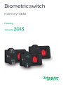
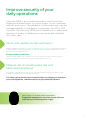
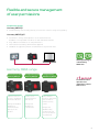
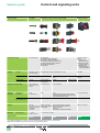
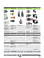
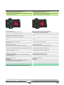
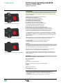
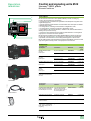
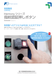
Biometric switch
Harmony® XB5S
Catalog
January
2013
Harmony XB5S
Biometric switch
Improve security of your
daily operations
Harmony XB5S is an innovative biometric switch that uses
fingerprint authentication to control access to your machines,
vehicles, and rooms. The database of authorized users can be
managed directly on the device or externally via a PC or HMI
interface. The Harmony XB5S switch enables you to determine
the level of access to different process areas and individual
HMI menu tabs.
Quick and reliable access verification
Using fingerprint recognition, the Harmony XB5S biometric switch is a competitive alternative
to other access control systems that do not provide sufficient levels of protection for your
process functions and personnel.
Simple, reliable and efficient
Harmony XB5S enables you to restrict access to sensitive zones and machine functions
(starting, adjustment, maintenance, etc.) to authorized personnel only.
Mitigate risk of unauthorized use and
associated downtime
The Harmony XB5S biometric switch is an automated solution that ensures that only the
entitled persons attend to your key process areas.
This allows you to prevent unwarranted machine use, helping you to protect
your staff, equipment, and the continuity of your production process.
Your finger is a unique access controller !
Fingerprint recognition is one of the fastest and most
accurate ways of verifying access rights.
1
Control access to your critical
assets and areas
Can you modify this
specific process?
Yes, if you’re authorized.
With Harmony XB5S, you can identify,
authorize and track user operations
on HMIs.
Can you operate this
automated line?
Yes, if you’re authorized.
With Harmony XB5S, you can improve
security of your automated lines and
tool machines.
Can you access this robot area?
Yes, if you’re authorized.
With Harmony XB5S, you can control
access to restricted areas.
Can you drive this forklift?
Yes, if you’re authorized.
With Harmony XB5S, you can prevent
unwarranted access to the start function of
special vehicles.
2
Flexible and secure management
of user permissions
Simple to manage:
Harmony XB5S1/2
•
Parameterizing and recording directly on front face of device using LED signalling
Harmony XB5S3/4/5
•
•
•
•
Visualization, saving and duplication of the authorized user
database is now possible via HMI or PC and dedicated software
Easy addition and deletion of user permissions
Data transfer secured by administrator approval
Database encrypted to prevent unwarranted use of personal data
With Vijeo Designer
and Harmony
XB5S Soft
Harmony XB5S range
Stand-alone product
Harmony XB5S1/2
Configuration by PC
Harmony XB5S3/4
Configuration by
HMI Harmony XB5S5
<to authenticate
1 second
an
operator and
authorize or refuse
their access
Improve control of
access to equipment
and restricted areas.
Restrict use of
special machines
and vehicles.
Manage embedded
database of
authorized users
directly on the
product.
Manage user
database via
a PC interface.
Define different
profiles of authorized
users on HMIs to
enhance security
control.
Manage user
database easily
via HMI; track and
store access data of
recorded users.
3
Content
Harmony® XB5S Biometric switch
Control and signaling units selection guide. . . . . . . . . . . . . . . . . . . . . . . . page 6
Biometric switch selection guide. . . . . . . . . . . . . . . . . . . . . . . . . . . . . . . . . page 8
bb Presentation. . . . . . . . . . . . . . . . . . . . . . . . . . . . . . . . . . . . . . . . . . . . . . page 10
1
vv Mounting. . . . . . . . . . . . . . . . . . . . . . . . . . . . . . . . . . . . . . . . . . . . . . . . . . page 10
vv Environment. . . . . . . . . . . . . . . . . . . . . . . . . . . . . . . . . . . . . . . . . . . . . . . page 10
bb Description. . . . . . . . . . . . . . . . . . . . . . . . . . . . . . . . . . . . . . . . . . . . . . . . page 11
bb References . . . . . . . . . . . . . . . . . . . . . . . . . . . . . . . . . . . . . . . . . . . . . . . . page 11
vv Complete units. . . . . . . . . . . . . . . . . . . . . . . . . . . . . . . . . . . . . . . . . . . . . . page 11
2
vv Accessories . . . . . . . . . . . . . . . . . . . . . . . . . . . . . . . . . . . . . . . . . . . . . . . . page 11
3
4
5
6
7
8
9
10
5
Control and signaling units
Selection guide
Type of products
Pilot lights
Pushbuttons, selector switches and pilot lights
Biometric switches
b Pushbuttons
b Multiple-headed pushbuttons b Emergency Stop pushbuttons
b Emergency switching off pushbuttons
b Selector switches and key switches
b Illuminated pushbuttons
b Pilot lights
Fingerprint readers
.
24V c
.
b Stand-alone
.
biometric switches
b Stand-alone USB
biometric switches
b USB biometric
switches dedicated
to Schneider HMI (1)
.
1
2
3
4
Description of range
. b LED pilot lights
.
.
Features
. Monolithic, compact, Complete units or sub-assemblies (body + head)
low consumption
5
6
7
8
9
Bezel
Double insulated
Shape of head
Circular
Monolithic
Metal, chromium plated or
black
Double insulated
Circular, square .
or rectangular
Circular
Circular or square –
Drilling or cut-out for fixing
. Ø 8 mm and Ø 12
mm/0.315 in. and
. 0.472 in.
.
Ø 16 mm/0.630 in.
Ø 22 mm/0.866 in.
Degree of
protection
. IP 40
. IP 65 with seal
IP 65
IP 66
IP 69K (Selector switches and key switches,
multiple-headed pushbuttons and Emergency
Stop pushbuttons with bellows)
Conforming to
IEC 60529
Conforming to UL 508
and CSA C22-2 N° 14
Cabling
Mounting
10
Products
–
.
.
.
.
Panel thickness
Type references
Enclosure type 4, 4X and 13
Tags for
Faston connectors
2.8 x 0.5 mm/ 0.110 x Solder pins for printed
0.020 in. connectors circuit boards
or threaded
connector
1…6 mm/0.039…0.236 in.
XVLA
XB6
XB4
(1) Compatible with Magelis iPC, STU, OT, GXO, GT (except GT1000 series), GK, GH, and GTO models.
(2) Wireless and batteryless pushbutton and receiver ready-paired at the factory.
6
IP 65 (control button)
Enclosure type 12
Spring clamp terminal connections
Screw clamp terminal connections
Faston connectors
Connector
With adaptor for printed circuit board
1…8 mm/
0.039…0.315 in.
Double insulated,
dark grey
XB5
Cable or connectors
XB5S
.
.
Wireless and batteryless Pushbuttons, selector
pushbuttons
switches and pilot lights
Joystick controllers
Pushbuttons, selector
switches and pilot lights
Cam switches
1
2
3
4
b Wireless and
batteryless
pushbuttons and rope
pull switch
b Configurable receivers
b Access point
b Relay-antenna
b Mobile handy box or
plastic boxes for wall
mounting
b Pushbuttons b 2 or 4 direction
b Emergency Stop and
b Stay put or spring return
Emergency switching off
pushbuttons
b Selector switches and key
switches
b Illuminated pushbuttons
b Pilot lights
Ready-to-use packs (2)
Monolithic
and «components» range
Complete units or sub-assemblies
(body + head with lever)
Metal, chromium plated or Double insulated, dark grey
double insulated, black
(or white for pilot lights)
Metal, chromium plated
Transmitter with circular
head
Circular
Circular
b Switches
b Stepping switches
b Reversing and changeover
switches
b Ammeter switches
b Voltmeter switches
b Reversing switches
b Star-delta and reversing
star-delta switches
b Pole change switches
Complete units or
sub-assemblies.
(body + head)
Complete units or subassemblies (body + front panel
+ head)
Double
Metal, chromium plated or double insulated, black
insulated,
black
Ø 22 mm/0.866 in.
IP 66
b Pushbuttons
b Emergency Stop buttons
b Selector switches and key
switches
b Illuminated pushbuttons
b Pilot lights
IP 65
Hexagonal
Square
Ø 30 mm/1.181 in.
Ø 16 or Ø 22 mm/0.630 or
0.866 in.: series K10
Ø 22 mm/0.866 in. and multifixing:
series K1/K2
4 holes, 48 or 68 centres: series
K30…K150
IP 66
IP 65: series K10
IP 40, IP 65 with seal: series
K1/K2
IP 40: series K30…K150
Enclosure type 4 and 13
(9001K)
Enclosure type 4, 4X, 13
(9001SK)
–
IP 65
IP 65 (control buttons and
pilot lights)
IP 54 (Emergency switching
off pushbuttons)
IP 65
Enclosure type 12
Enclosure type 3
(pushbuttons and
Emergency stop)
and 4 (pilot lights)
Enclosure type 4, 4X and 13
Wireless (transmitter)
Through cable (receiver)
Screw and captive clamp
Screw and captive clamp terminal connections
terminal connections
Faston clip connections (pilot
lights)
1…6 mm/0.039…0.236 in.
XB5R, XB4R
5
6
7
8
9
0.5…6 mm/0.020…0.236 in.
(depending on model)
XB7
XD4PA XD2GA XD5PA 9001K, 9001SK
K10, K1, K2, K30, K50,
K63, K115, K150
7
10
Selection guide
Control and Signaling Units Ø 22
Harmony® XB5S, plastic
Biometric switches for fingerprint recognition
1
Applications
Simple access control for indoor industrial restricted areas
Type of products
Stand-alone biometric switch
Functions
b 1 level of authorization
b Authorizes user through fingerprint recognition
Static Output
b Bistable output, machine operation at 2 fixed states
b Monostable output, machine operation at pulse control
Power
24 V DC
Connection
b Pre-wired 3 wire cable (2 m/6.56 ft long) or
b M12 connector
Memory capacity
b 200 records of fingerprints
b 100 authorized users with each registering 2 fingerprints or 200 authorized users with each
registering 1 fingerprint
Communication
No communication
Database management
software tools
None
.
User database update
Stand-alone as updates are done directly on the biometric switch
Associated accessories
b Translucent protective cover
b Fixing nut
b Legend plate
Type references
XB5S1, XB5S2
2
3
4
5
6
7
8
9
(1) Compatible with Magelis iPC, STU, OT, GXO, GT (except GT1000 series), GK, GH and GTO models .
(2) Compatible with all versions of Harmony XB5SSoft application. The XB5SSoft is a freeware application and can be downloaded from our website
www.schneider-electric.com.
10
8
bSecure the control of automated lines and tool machines
bProtect the start function of special vehicles
bIdentify and authorize the user for HMI operations
bTrace the HMI operations of each user
Stand-alone USB biometric switch
USB biometric switch dedicated to Schneider HMI (1)
1
2
3
b 1 level of authorization
b Authorizes user through fingerprint recognition
b Provides access to HMI pages based on the user profile
b Several levels of authorization associated with HMI
b Traceability of users and operations by HMI
b Bistable output, machine operation at 2 fixed states
b Monostable output, machine operation at pulse control
None
24 V DC
24 V DC
b Pre-wired 3 wire cable (2 m/6.56 ft long) or
b M12 connector
Pre-wired 2 wire cable (2 m/6.56 ft long)
b 400 records of fingerprints
b 200 authorized users with each registering 1 or 2 fingerprints
b 400 records of fingerprints
b 200 authorized users with each registering 2 fingerprints
Connects with a PC via the USB port for database management when required
Connects with a HMI via the USB port permanently
With Harmony XB5SSoft (2) on a PC
With Vijeo Designer (3) and Harmony XB5SSoft (2)
b Should be connected to a PC
b Download the new user database to the biometric switch from Harmony
XB5SSoft application (4)
b With VijeoDesigner in Run time on HMI (4)
b With VijeoDesigner in Build time on PC (4)
b Translucent protective cover
b Fixing nut
b Legend plate
b Female/Female USB extension cable with a female USB port of
Ø 22 mm/0.866 in. on one end for panel mount
b Translucent protective cover
b Fixing nut
b Legend plate
XB5S3, XB5S4
XB5S5
4
5
6
7
8
(3) Compatible with VijeoDesigner HMI editor software V6.1, Service pack 2.
(4) The user database cannot be uploaded from biometric switch to the PC.
9
10
9
Presentation
Control and signaling units Ø 22
Harmony® XB5S, plastic
Biometric switches
Presentation
1
The biometric switches of the Harmony® XB5S range are designed to control and
secure access to systems and machines by checking users’ authorization through
fingerprint recognition.
2
The following types of biometric switches are available:
b Stand-alone biometric switches
v type XB5S1, with 2 fixed states (bistable)
v type XB5S2, with pulse control (monostable)
b Stand-alone USB biometric switches
v type XB5S3, with 2 fixed states (bistable)
v type XB5S4, with pulse control (monostable)
b USB biometric switches dedicated to Schneider HMI
v type XB5S5, connected permanently with HMI
Stand-alone biometric switch (XB5S1/XB5S2)
The biometric switches are aimed at 2 categories:
b Administrators, who decide and manage the list of users
v the only people who can record the fingerprints in the device memory
b Users, who are authorized to use the biometric switch as a control unit
v at least 1 of their fingerprints should be recorded in the device memory
v access is granted when the finger is placed on the sensing screen
3
The USB switches communicate with the PC/HMI via the USB port to manage the
user database. This database can be visualized, saved, and duplicated by PC/HMI
with XB5SSoft application (1) (2). The fingerprint records can also be erased in the
absence of users.
4
Stand-alone USB biometric switch (XB5S3/XB5S4)
5
The Schneider HMI (3) with VijeoDesigner software (4) enables the switches to
authorize different access levels and trace HMI operations of each user.
The switch operates on 24 V DC and provides protection against:
v Reverse polarity
v Overload and short-circuit (switching capacity y 200 mA)
Mounting
The product is of monolithic design (a single plastic housing) and is fixed by means of
a nut (hand-tightened without need for tools) in a standard 22.5 mm/0.886 in. diameter
hole. It can be installed on a flat, horizontal, or vertical surface.
6
A protective cover is available as an accessory to protect the active face of the
sensing screen. This cover is fixed using a self-adhesive hinge.
7
USB biometric switch dedicated to Schneider HMI (XB5S5)
A Female/Female USB extension cable makes it possible for the USB biometric
switch to have the female USB port within a 22 mm/0.866 in. diameter hole on the
control panel front.
Environment
b Conformity to standards: UL, CSA, GOST, and e.
b Product certifications:
v CSA C22-2 n° 14
v UL 508
v IEC 61000-6-2 and IEC 61000-6-4
8
b Degree of protection conforming to standard IEC 60529:
v IP 65
v NEMA 12
9
b Ambient air temperature:
v For storage: - 25 to + 70 °C
v For operation: - 5 to + 50 °C
(1) Compatible with all versions of Harmony XB5SSoft application. The XB5SSoft is a freeware
application and can be downloaded from our website www.schneider-electric.com.
(2) The user database cannot be uploaded from USB biometric switch to the PC.
(3) Compatible with Magelis iPC, STU, OT, GXO, GT (except GT1000 series), GK, GH, and
GTO models .
(4) Compatible with VijeoDesigner HMI editor software V6.1, Service pack 2.
10
10
Control and signaling units Ø 22 Description,
references
2
2
4
3
1
PF121408A
5
6
Harmony® XB5S, plastic
Biometric switches
Description
b The stand-alone biometric switch (XB5S1/XB5S2) consists of a dark gray
housing, with the following on its front face:
v A sensing screen 1 that allows the registration and subsequent recognition of the
registered fingerprints,
v A green LED output state indicator 2 that illuminates when the output is activated
(solid-state NO contact),
v An orange LED 3, indicating an administrator’s “Registration” mode,
v An orange LED 4, indicating an operator’s “Registration” mode,
v A red “RESET” LED 5 which indicates, in “Delete” mode, that the administrator is
deleting all or part of the memory,
v A red LED 6 which flashes when the reader is presented with an “unrecognized”
fingerprint or in the event of incorrect operation.
b The stand-alone USB biometric switch (XB5S3/XB5S4) consists of a dark gray
housing with a sensing screen 1 for fingerprints, a green LED 2 for indicating the
output state, and a red LED 6 for the unrecognized fingerprint on its front face.
b The USB biometric switch dedicated to Schneider HMI (XB5S5) consists of a dark
gray housing with a sensing screen 1 for fingerprints on its front face.
1
2
3
References
Complete units
Description
Bistable biometric switch
24 V DC
PNP output
XB5S1Bpppp
Monostable biometric switch
24 V DC
PNP output
PF121406A
Bistable USB biometric switch
24 V DC
PNP output
Monostable USB biometric
switch
24 V DC
PNP output
USB biometric switch .
dedicated to Schneider HMI
24 V DC
Connection
Reference
By 2 m/6.56 ft cable
XB5S1B2L2
Weight
kg/lb
0.170/0.375
By M12 connector
XB5S1B2M12
0.183/0.403
By 2 m/6.56 ft cable
XB5S2B2L2
0.170/0.375
By M12 connector
XB5S2B2M12
0.183/0.403
By 2 m/6.56 ft cable
XB5S3B2L2
0.202/0.445
By M12 connector
XB5S3B2M12
0.215/0.474
By 2 m/6.56 ft cable
XB5S4B2L2
0.202/0.445
By M12 connector
XB5S4B2M12
0.215/0.474
By 2 m/6.56 ft cable
XB5S5B2L2
0.202/0.445
4
5
6
7
XB5S3Bpppp
Accessories
PF121307A
Description
Function
Reference
Female/Female USB extension For connecting biometric
cable with Ø 22 mm/0.866 in.
switch to the PC via the .
female USB port on one end
Ø 22 mm/0.866 in. hole on
the control panel front
XB5SFFUSBEXT
Weight
kg/lb
0.108/0.238
Protective cover, translucent
and self-adhesive
Protection of sensing .
screen
ZB5SZ70
0.020/0.044
Fixing nut
Ø 22 mm/0.866 in.
Spare part
ZB5SZ71
0.030/0.066
Legend plate, 27 x 8 mm/.
1.06 x 0.32 in., self-adhesive,
blank, black background, for
engraving
_
ZBY0101T
0.005/0.011
8
569117
XB5SFFUSBEXT
ZB5SZ70
9
10
11
Head Office
35, rue Joseph Monier
F-92500 Rueil-Malmaison
France
The information provided in this documentation contains general descriptions and/or technical
characteristics of the performance of the products contained herein. This documentation is not
intended as a substitute for and is not to be used for determining suitability or reliability of these
products for specific user applications. It is the duty of any such user or integrator to perform the
appropriate and complete risk analysis, evaluation and testing of the products with respect to the
relevant specific application or use thereof. Neither Schneider Electric nor any of its affiliates or
subsidiaries shall be responsible or liable for misuse of the information contained herein.
Design: Schneider Electric
Photos: Schneider Electric
Printed by:
January 2013
DIA5ED2121215EN
www.schneider-electric.com/control
Schneider Electric Industries SAS


![[Silk Gimbal User Manual]](http://vs1.manualzilla.com/store/data/005969411_1-2c584c7da53e0ea80ffb995f6422f5dc-150x150.png)