1
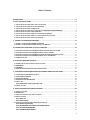
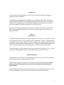
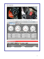
Installation and User Manual Centurion Diagnostic Software This Guide is intended to answer Centurion U/UI/M/I/S/HD questions and to act as a Quick Start Guide. It is not intended to be encyclopedic on the diagnostic/repair process - only to answer questions about Centurion U/UI/M/I/S/HD. This Guide will give some example of the screens available for you to perform your diagnostic. 1 Table of Contents INTRODUCTION........................................................................................................................................ 4 1. SETUP AND INSTALLATION................................................................................................................... 5 1.1 SETUP AND INSTALLATION: WHERE TO GET THE SOFTWARE ............................................................................ 5 1.2 SETUP AND INSTALLATION: INSTALL CENTURION U/UI ................................................................................. 7 1.3 SETUP AND INSTALLATION: RUN CENTURION .............................................................................................. 7 1.4 SETUP AND INSTALLATION: INSERT SECURITY KEY INTO USB (ONLY FOR PRO MODELS) .................................. 8 1.5 SETUP AND INSTALLATION: CONNECT USB CABLE ........................................................................................ 8 1.6 SETUP AND INSTALLATION: POWER UP THE CENTURION U/UI/M/I/S............................................................. 9 1.7 SETUP AND INSTALLATION: POWER UP TO AUTOMATICALLY INSTALL DRIVERS ................................................... 10 1.8 SETUP AND INSTALLATION: UPDATE YOUR SOFTWARE ................................................................................ 10 2. CONNECT THE CENTURION HARDWARE ............................................................................................ 11 2.1 CONNECT THE CENTURION U/UI/M/I/S HARDWARE ............................................................................... 11 2.2 CONNECT THE CENTURION HARDWARE: CONNECT THE USB CABLE ............................................................... 13 3. STARTING YOUR CENTURION U/UI/M/I/S SOFTWARE ....................................................................... 14 3.1 STARTING YOUR CENTURION U/UI/M/I SOFTWARE: INSERT SECURITY KEY INTO USB ...................................... 14 3.2 STARTING YOUR CENTURION U/UI/M/I SOFTWARE: RUN THE PROGRAM ...................................................... 15 3.3 STARTING YOUR CENTURION U/UI/M/I/S SOFTWARE: DISCLAIMER/LANGUAGE SELECTION ............................. 16 3.4 STARTING YOUR CENTURION U/UI/M/I SOFTWARE: SELECT THE COM PORT. ................................................ 17 3.5 COM PORT SETTING .......................................................................................................................... 18 4. USING THE CENTURION U/UI/M/I/S .................................................................................................. 19 4.1 CONNECTING TO YOUR MOTORCYCLE AND KEY FEATURES: ........................................................................... 19 4.2 MAIN MENU .................................................................................................................................... 21 4.3 TAB MENU ...................................................................................................................................... 21 4.4 CENTURION TOOLBAR (FOR BOTH SINGLE AND PRO USERS) ........................................................................ 21 5. CENTURION TOOLBAR ICON DESCRIPTION (FOR BOTH SINGLE AND PRO USERS) .............................. 23 5.1 TOOLBAR BUTTONS/COMMANDS IN-DEPTH ........................................................................................... 23 5.2 GAUGES/METERS WINDOW ................................................................................................................ 24 5.3 STRIP CHART WINDOW ...................................................................................................................... 24 5.4 HORIZONTAL SLIDE BARS WINDOW ....................................................................................................... 25 5.5 ACTIVE TEST ..................................................................................................................................... 25 5.5.1 TSSM testing → Harley Davidson only ................................................................................... 26 5.6 ACTIVE SETTINGS............................................................................................................................... 27 6. HARLEY-DAVIDSON TESTS AND ACTIVATIONS................................................................................... 30 6.1 SPECIFIC FUNCTIONS ........................................................................................................................... 30 6.2 CONNECTING .................................................................................................................................... 31 6.3 SELECT THE PROCEDURE YOU WANT TO PERFORM ...................................................................................... 31 6.4 SELECT FUNCTION .............................................................................................................................. 32 6.4.1 Active Test ............................................................................................................................. 32 6.4.2 Active Settings ....................................................................................................................... 32 6.5 SPECIFIC FUNCTIONS FOR HARLEY-DAVIDSON MOTORCYCLES ....................................................................... 33 6.5.1 Module Programming............................................................................................................ 33 6.5.2 ABS BLEEDING* NOT HARLEY DAVIDSON SPECIFIC................................................................. 34 6.5.3 KEY FOB PROGRAMMING ...................................................................................................... 35 6.5.4 ALARM DISSABLE/ENABLE ..................................................................................................... 36 2 7. HOW TO CHANGE UNITS/COLORS...................................................................................................... 38 7.1 HOW TO CHANGE UNITS AND COLORS ..................................................................................................... 38 7.1.1 Color settings menu............................................................................................................... 39 7.1.2 Select channel for color change ............................................................................................. 39 7.1.3 Select color ............................................................................................................................ 39 8. MONITOR REAL-TIME DATA (GAUGES/METER DISPLAY) .................................................................... 40 8.1 MONITOR DATA ............................................................................................................................... 40 8.3 CHANGE VISIBLE PARAMETER ............................................................................................................... 41 8.4 SELECT PARAMETER ........................................................................................................................... 41 8.5 COMMUNICATE................................................................................................................................. 42 9. MONITOR REAL-TIME DATA (STRIP CHART DISPLAY/METER DISPLAY)............................................... 44 9.1 VIEW DATA...................................................................................................................................... 44 9.2 TURN IGNITION TO RUN ...................................................................................................................... 45 9.3 COMMUNICATION ............................................................................................................................. 45 9.4 START ENGINE .................................................................................................................................. 46 9.5 CHANNEL MODE ............................................................................................................................... 46 9.6 CHANNEL DISPLAY ............................................................................................................................. 47 9.7 SELECT PARAMETER ........................................................................................................................... 48 9.8 SELECT DISPLAY ................................................................................................................................ 49 10. LOCATION OF DIAGNOSTIC CONNECTORS........................................................................................ 49 10.1 LOCATION OF DIAGNOSTIC CONNECTOR IN HARLEY DAVIDSON MOTORCYCLES ................................................. 49 10.2 LOCATION ON DUCATI MOTORCYCLES .................................................................................................. 50 10.3 LOCATION ON MV AGUSTA MOTORCYCLES ........................................................................................... 51 GLOSSARY.............................................................................................................................................. 52 3 Introduction The Centurion Scan-Tool Software is a user-friendly software tool able to diagnose engine and system problems. This Windows-based program was designed to communicate with a wide variety of Engine Control Units (ECUs). The interface between the ECU and the PC is via an RS232 interface box. The graphic user interface (GUI), along with the help screens, hotkeys, and mouse support, combine to provide a user friendly system. The main GUI consists of a pull-down menu and a tool bar. The execution of the menu items is accomplished through numeric controls, command button controls, pop-up panels and others. Basics How it works The ECM is basically a calculator that sends signals to the injectors. The sensors include the temperature of the motor (Harleys head temperature sensor), outside ambient temperature and pressure (altitude), throttle position (TPS), engine speed (RPM) and load (KPA or MAP, manifold absolute pressure). The newer models (2008 and later) also have a narrow band O2 sensor and actually run in “closed loop” when you tell it to. The ECM combines all data gathered by those sensors and compares it to the actual conditions, making adjustments so that the engine works its best at all times. About this Manual The Centurion User’s Guide is a comprehensive guide that contains all of the procedures you will need in order to work with this software. This manual is organized by chapters to assist novice users with getting started. Many topics covered in this manual are also covered in the help menus available in the program itself. This Guide/Manual has been written thinking that not only professionals will use it, but also non-professionals. That is the reason it is written in a non-technical way. 4 1. Setup and installation 1.1 Setup and installation: where to get the software Insert the CD-ROM from TechnoResearch Inc. into the DVD/CD-ROM drive of your computer… OR download from our website (www.technoresearch.com Go to Support > Downloads). For many users, downloading is better since you will get the latest versions and you can download before receiving your equipment. 5 NOTE: Download the Centurion software, the Software updater and the USB driver software from the Centurion tag. 6 1.2 Setup and installation: install Centurion U/UI After auto-run, press install button under the icon for Centurion U/UI/M/I. 1.3 Setup and installation: run Centurion Double-click on the Centurion U/UI/M/I/S icon on your desk top to run the program. This will install the USB security hardware key driver necessary for step 4. 7 1.4 Setup and installation: insert security key into USB (ONLY FOR PRO MODELS) Insert the provided pre-programmed USB product security hardware key, (color matched for application), into the USB port of your computer. This will enable the software to run. 1.5 Setup and installation: connect USB cable Connect the USB cable (shown below at left) to the Vehicle Communication Module (VCM). The module is shown below, with the USB port on the right side of the metal endplate. Connect the other end to your PC’s second USB port. 8 NOTES: • The supplied USB Hardware Key with this software is for use only with the specific Centurion U/UI/I/M software. • NEVER plug in multiple hardware keys. For example: do not plug in a Centurion U/UI key and a DirectLink key! 1.6 Setup and installation: power up the Centurion U/UI/M/I/S Connect the Vehicle Communication Cable to the DB-15/AMP3/Sicma port on the other end of the Vehicle Communication Module. Connect the other end to the motorcycle’s data link connector. If you cannot locate your bike’s data link connector, please consult your motorcycle user manual. To avoid damaging the cables, keep them clear of the exhaust 9 1.7 Setup and installation: power up to automatically install drivers Having completed Step 6, the system will now be powered up. The VCM is powered by the battery of the motorcycle. Make sure the ignition is ON and the RUN switch is ON. The light on the VCM should be lit. This will cause the software to search for the cable drivers. This will prompt you to select the folder called ‘USB 2.0 Cable Drivers’. The software will find and install the drivers. 1.8 Setup and installation: update your software After the Centurion software is installed, you must run the updater to get the latest program versions, including the calibrations and the manuals. Click the "Updater” icon on the opening screen. 10 2. Connect the Centurion Hardware 2.1 Connect the Centurion U/UI/M/I/S Hardware Connect the Centurion U/UI/M/I/S Hardware and the motorcycle's data link connector using the Deutz (4 pin or 6 pin), 3AMP, or Sicma connector cable in the kit, as well as the alligator clips to the battery. Location of diagnostic connector varies from motorcycle to motorcycle. For show purposes, a Ducati Monster with 3AMP connector was used. 11 To avoid damaging the cables, keep them clear of the exhaust TIP: If your bike does not have a headlight OFF/ON switch, you might want to take out the fuse so that the battery doesn’t die. 12 2.2 Connect the Centurion Hardware: Connect the USB cable Connect the Centurion U/UI/M/I/S Hardware to the computer using the USB cable in the kit. 2.3 Connect the Hardware (for Centurion U/UI/M/I users only): Insert Security Key into USB Connect the USB security key to a second USB port on your computer. 13 3. Starting your Centurion U/UI/M/I/S software 3.1 Starting your Centurion U/UI/M/I software: insert security key into USB Insert the USB Hardware Key into your computer’s USB port to use the Centurion U/UI/M/I software (Centurion Pro only). For Centurion S users, make sure your Centurion tool is properly connected to the vehicle’s battery and that the ignition and Run/Stop switches are in the “ON” position. 14 3.2 Starting your Centurion U/UI/M/I software: run the program Click Centurion U/UI/M/I icon on the desktop to run the software. 15 3.3 Starting your Centurion U/UI/M/I/S software: Disclaimer/Language selection Click “Accept” and select your language of preference. For single user, select “Centurion Standard”. 16 For shops or users with multiple bikes, select “Centurion Pro”. 3.4 Starting your Centurion U/UI/M/I software: select the COM port. This process should be done automatically. If there are issues during this process or COM Port is not automatically selected, see next step. 17 3.5 COM port setting If COM port is not showing, (see picture below) you will get this message: It means that the driver for it was not correctly installed when installing the Centurion U/UI/M/I software. Please follow these instructions on how to install the USB 2.0 driver. Note: These screen shots were taken on a Windows®7Pro equipped computer. Your computer might look different! After you have updated or installed the correct device driver, you should get a screen like this: This process is very similar in Windows XP and Windows 8 equipped computers. 18 4. Using the Centurion U/UI/M/I/S 4.1 Connecting to your motorcycle and key features: In order to display the data you wish to monitor, you must first establish a connection with the ECU and then set the program to either dashboard mode or strip chart mode. To establish communication*, select the ‘Connect’ command, either by clicking on the connect icon or by using the communication drop down menu. *If you have a Centurion S model, the tool is already pre-configured for your specific ECU. Just click the Connect icon or Connect under the communication drop down menu. *If you have a Pro model, M/U/UI, you must first select the motorcycle or ECU model you are going to work on for the software to correctly select the data. You do this by clicking on the “Motorcycle” or Select brand/ECU/Model icon, then, click the Connect icon or under the Communication tab, click Connect 19 Note: When communication with the ECU is lost or could not be established, the data will not be able to be displayed and an error message dialog box will come up. 20 4.2 Main Menu The Centurion main menu offers a variety of commands. To open the menus and see the available commands, either point and left click on the menu name, or press ALT + the underlined letter in the name of the menu you wish to open. Below the main menu are the Toolbar Buttons, which offer quick access to the most often used commands. 4.3 Tab Menu File Menu: Commands to open a file, export one, close an active window and quit the program View Menu: Contains commands related to data monitoring Communications Menu: Commands for connecting to the ECU, disconnecting from the ECU and selecting port settings Options Menu: Commands to select log settings, toggle log on or off, select O2/Gas Analyzer, select the ECU or model, select channels, units and color settings Utilities Menu: Contains the calculator and unit conversions Help Menu: Displays a variety of help commands 4.4 Centurion Toolbar (for both Single and Pro Users) The toolbar buttons allow one-click access to the most frequently used commands. Click to: Open data analysis Print Monitor data in dashboard (gauges/meters) mode 21 Monitor data in strip chart mode Horizontal Slide Bars Active Test Active Settings View Diagnostic Trouble Codes System Status Anti-Theft Status Antilock Brake System Status Cable specification Establish connection with ECU Disconnect from ECU Log on and Log off data recording Select brand/ECU/model Select data channel to be monitored Metric/English unit conversions Activate the calculator Measurement unit conversions 22 5. Centurion Toolbar icon description (for both Single and Pro Users) 5.1 Toolbar Buttons/Commands In-Depth Open Data Log for Analysis Opens a dialog box, where you can open the file with the data log that has been created. Please note: to make this feature available, you must first set the ‘Recording’ feature to ‘On’. If it is set to ‘Off’, a log will not be created. The software will create a filename for your data log based on date (and sequence, if applicable). Print Prints a copy of your data log Gauges/Meters The Gauges/Meters button enables viewing of data through bar slides, graphs, thermometers and check lights. It offers 6 configurable channels. Please note that the round gauges at the top of this screen are not configurable; those four gauges are set to always show those four data elements. Strip Chart The Strip Chart Monitor button is used to view data in line plot and numerical form. It offers 16 configurable channels. Horizontal Slide Bars The Horizontal Slide Bars button is used to view data with horizontal slide bars. It offers 4 configurable channels. TIP: Most Commonly-Used Channels (Gauges/Meters, Strip Chart & Horizontal Bar Slides Viewing Modes) RPM: Engine RPM numeric value Battery: Battery voltage numeric value Spark Advance: Spark adv. angle numeric value Pulse Width: Pulse width numeric value → Injection time Throttle Position: Throttle angle numeric value Air Temperature: Air temperature numeric value Engine Temperature: Engine temperature numeric value Barometric Pressure: Barometric pressure numeric value Stepper Motor: Stepper motor numeric value (Please note that any data element that is grayed out is not available for that ECU.) 23 5.2 Gauges/Meters Window 5.3 Strip Chart Window 24 5.4 Horizontal Slide Bars Window 5.5 Active Test This window has several functions including testing the actuators and adjusting the Trim EEPROM. This window is used to perform several operations, such as the Clear DTC button will clear readings from the ‘Historic’ box of the DTC window. 25 5.5.1 TSSM testing → Harley Davidson only 26 5.6 Active Settings This window is used to perform several operations. The Clear DTC button will clear readings from the ‘Historic’ box of the DTC window. DTC Read 27 OR 28 Diagnostic Trouble Code & Function Errors This window displays both current errors (even those that may appear very briefly), as well as historic errors. Please note that current errors that appear very briefly may not show in the historic box. O.C. = open circuit S.C. = short circuit High V. = high voltage Low V. = low voltage 29 6. Harley-Davidson tests and activations 6.1 Specific functions Select the ECU type you are testing by clicking on the Motorcycle icon for Brand/ECU. Select Harley Davidson and then the drop down menu (for HD, it will only show ECU/ECM type), choose your ECU, then click OK. 30 6.2 Connecting Turn ON the ignition switch and make sure the engine stop/run switch is in the RUN position. Click CONNECT. 6.3 Select the procedure you want to perform *PLEASE NOTE THAT INJECTOR TESTING CANNOT BE PERFORMED ON BIKE— INJECTORS MUST BE TAKEN OFF AND BENCH TESTED. or or 31 6.4 Select function After you have selected the procedure, select the function you want: 6.4.1 Active Test 6.4.2 Active Settings Active settings allow you to change the values of some parameters as long as they were changeable from the factory. 32 6.5 Specific functions for Harley-Davidson motorcycles 6.5.1 Module Programming 1. SELECT THE IDLE MODULE REPLACEMENT TAB ON ACTIVE SETTINGS 2. CLICK ON CALIBRATE 3. PROMPT WILL ASK YOU TO START ENGINE [DO NOT CLICK OK BEFORE STARTING ENGINE], START ENGINE 4. ENGINE WILL DIE 5. WAIT 10 SECONDS 6. CLICK OK 33 6.5.2 ABS BLEEDING* NOT HARLEY DAVIDSON SPECIFIC 1. SELECT ABS TAB ON ACTIVE SETTINGS 2. CLICK ON ACCEPT FOR THE SETTING TO BECOME “LIVE” 3. SELECT WHICH BRAKES YOU ARE GOING TO WORK ON 4. FOLLOW INSTRUCTIONS 5. HOLD BRAKE LEVER WITH CONSTANT PRESSURE. AFTER YOU HAVE FINISHED, CLICK OK 6. REPEAT SAME PROCEDURE FOR REAR BRAKE *INSTRUCTIONS ARE BASED ON THAT YOU HAVE ALREADY PERFORMED A MECHANICAL BLEEDING PROCEDURE!!! 34 6.5.3 KEY FOB PROGRAMMING 1. SELECT KEY FOB TAB ON ACTIVE SETTINGS 2. CLICK ON THE KEY-FOB BUTTON TO TEST THE SYSTEM 3. NUMBER EACH KEY FOB AS NUMBER 1 AND NUMBER 2. OPEN THEM TO MAKE SURE OF THAT THE CODES DISPLAYED ARE CORRECT 4. WRITE THE NEW KEY FOB’S CODE WHERE THE DAMAGED KEY FOB CODE WAS 35 6.5.4 ALARM DISSABLE/ENABLE 1. SELECT THE KEY FOB TAB 2. WRITE YOUR PERSONAL KEY CODE 36 3. SELECT ON/OFF 4. CLICK ON PROGRAM 37 7. How to Change Units/Colors 7.1 How to change units and colors Go to "Options" menu and select "Units". Select the unit that you want to use. Click "OK". 38 7.1.1 Color settings menu Go to "Options" menu and select "Colors". Select the unit that you want to use. Click "OK". 7.1.2 Select channel for color change Select the channel of which you want to change the color. 7.1.3 Select color Select the color you want. You can also change the background. 39 8. Monitor Real-time data (Gauges/Meter display) 8.1 Monitor Data Monitor the Real-time data with Gauges/Meters display. Go to "View" and select "Gauges/Meters", or just click "Gauges/ Meters" icon. 8.2 Change Channels If you want to change the visible data, go to "Options" and select "Channels/Mode", or just click "Channels/Mode” icon. 40 8.3 Change Visible Parameter There are six channels. Click the gray square button for the drop down menu if you want to change the visible parameter. 8.4 Select Parameter Select a parameter that you want to display. Click "OK". 41 8.5 Communicate Turn on the ignition switch and make sure the engine stop switch is in the RUN position. Go to "Communication" and select "Connect" or just click "Connect” icon. 42 For best monitoring the engine, we recommend to select the following 6 channels: 1. 2. 3. 4. 5. 6. Tachometer - RPM Throttle Pos Engine Temp Battery Voltage Air Temp Atm Pressure Any other information is optional and up to personal preferences. 43 9. Monitor Real-time data (Strip Chart display/Meter display) 9.1 View Data Monitor the Real-time data with Strip Chart display. Go to "View" and select "Strip Chart" or just click "Strip Chart” icon. You might add engine (temp) to make sure you’re never running the engine hot when recording and that the motor is in the operating temp range. For best monitoring the engine, we recommend to select the following 6 channels: 1. 2. 3. 4. 5. 6. Tachometer - RPM Throttle Pos Engine Temp Battery Voltage Air Temp Atm Pressure Any other information is optional and up to personal preferences 44 9.2 Turn ignition to run Turn on the ignition switch and make sure the engine stop switch is in the RUN position. 9.3 Communication Go to "Communication" and select "Connect" or just click "Connect” icon. 45 9.4 Start Engine Start the engine. Now you can monitor Real-time data. 9.5 Channel Mode If you want to change the showing parameter, go to "Options" and select "Channels/Mode" or just click "Channels/Mode” icon. 46 9.6 Channel display You can display up to sixteen channels at a time. If you want to increase or reduce the number of channels, click "on/off" switch. ON: Show the selected channel. OFF: Hide the selected channel. 47 9.7 Select parameter Click on the "Arrow" button if you want to change the visible parameter. Select a parameter that you want to display and then click OK. 48 9.8 Select Display Select "Parallel display" or "Overlay display". Click "OK". 10. Location of diagnostic connectors 10.1 Location of diagnostic connector in Harley Davidson Motorcycles 2001-2013 Softail Models Located under the seat, attached to the frame by the rear fender. Plug is Grey in color, with black rubber plug installed. *Requires removing the seat 2004-2013 Dyna Models Located behind the Lh side cover. Connector is Light Grey in color with black rubber plug installed. . 2007-2013 Sportster Models (includes XR Models) Located behind the Lh side cover. Plug is Grey in color with black rubber plug installed. 2002-2013 V-Rod Models Diagnostic connector is located behind the Right Front frame cover. Plug is Grey in color with black rubber plug installed. You will need tools o remove the cover. 49 2002-2007 Touring Models Diagnostic connector is located behind the right hand side cover. Plug is Grey in color with black rubber plug installed. Accessible by removing the Rh side saddle bag. 2008-2013 Touring Models Diagnostic connector is located behind the left hand side cover. Plug is Grey in color with a black rubber plug installed. Accessible by removing the Lh side saddle bag. 10.2 Location on Ducati Motorcycles Monster 2001~2007 [620-695-750-800-900-1000-S4-S2R800/1000S4R/S/T] Under the tank Rh side by ECU You will need to remove seat and lift fuel tank to access 3AMP connector and battery Monster 2008~present [696/796/1100/S/EVO] Under the seat by the battery MTS620/1000DS/1100/S Front LH lower cover, careful when you pull out the cover. Battery is also accessible here. MTS1200/S/T Under the seat. Diavel Under the seat Hypermotard Gen 1 Magnetti Marelli ECU 2007~2009[1100/S] & Gen 1 Siemens ECU2009~ present [796/1100EVO/EVO SP] Under tank MH900IE Rh side under dashboard SBK 748/916/996/998/S/RS/SP/SPS Front side of LH side of engine at bottom –Must remove Lh fairingSBK 749/999/S/R Front side of LH side of engine at bottom –Must remove Lh fairingSBK 848/1098/1198/S/R/Tricolore/EVO/Hayden/CORSE Front side of LH side of engine at bottom –Must remove Lh fairing50 SBK 888 with P8 ECU Under the seat SuperSport SS [620-750-800-90-1000DS] Under the seat Sport Classic [GT1000-Paul Smart-Sport] Under the tank Sport Touring ST2/3/4/S Under the seat StreetFighter [848/1098/S] Under the seat DS16RR Under the seat 10.3 Location on MV Agusta Motorcycles Brutale, F4: 750/1000 Under the seat by the battery This manual has been written for the professional and the DIYer Centurion user. That is the reason it is written in a non-technical language and with as much step by step images. This manual will continue to be updated with new text and/or images as the need for new or clearer instructions becomes apparent. 51 Glossary ECM/ECU (Electronic control module/unit): This is the brain of the motorcycle; it makes calculations based on inputs coming from sensors mounted all over the engine. WOT (Wide open throttle): The maximum opening of the throttle valve. AFR (Air fuel ratio): The relationship of parts of fuel to the parts of air. 13.0(air) to 1(fuel) usually makes the best power, and 14.6 is considered “perfect” air fuel ratio. This would be the AFR to get an ideal burn (theoretically). This would be at perfect atmospheric conditions and temps, with a perfect atomization which is almost impossible. MAP (Manifold absolute pressure): These sensors measure barometric absolute pressure in the intake manifold. By calculating the mass of the air going into the engine, air temperature, and the rotations per minute of the engine, the engine’s ECU can determine the density of the air flowing into the fuel mixture. The ECU can then adjust air flow or fuel flow. CKP or CP (Crank position sensor): This sensor tells the ECM when to fire and inject fuel depending on how fast the engine is running in Revolutions Per Minute. IAT (Intake air temperature): The ECM calculates how dense the air is from this input. ET (Engine temperature): The ECM uses the signals from this sensor to determine if the engine is at operating temperature, or warming up. Fuel Pressure Regulator: A mechanical device usually operated by vacuum form intake manifold that controls fuel pressure. It returns excess fuel from the fuel pump back to the fuel tank. Fuel Injectors: The fuel injectors are electric valves that open and close to deliver fuel in spray form to the cylinder. They are controlled by the ECM to precisely deliver the correct amount of fuel at every engine speed or RPM and any given load. The time of injection is also known as the injector “pulse width” and is measured in milliseconds. Injectors are rated by their flow rate – such as in gm/sec, l/hr or grams per second. Electric Fuel Pump or Fuel Pump: A 12-volt high-pressure fuel pump, usually located in the fuel tank, but it can be located outside as well. It supplies pressurized fuel to the fuel injectors. IAC (Idle air control): An electric valve that’s threaded, to open and close as needed to let air into the engine for startup and idle operation when throttle valve is closed. 52 Closed Loop injection system: This circuit has 2 Oxygen sensors. The information on the difference of how much is coming out of the cylinder is relayed to the ECM and then adjusts the amount of fuel injected by shortening or lengthening the time the injectors are open. O2 Oxygen sensor (sniffer): This tells the ECM how much oxygen is in the exhaust mixture so as to have the correct mixture. Anything under 14.7 is considered a rich mixture and anything above 14.7 is considered a lean mixture. RPM (Revolutions per minute): Used to measure engine speed. TPS (Throttle position sensor): You will be dealing with percentages (0 to 100) or Degrees (°) and/or Volts (V). DDM (Drop down menu): selection of parameters available for a field. 53