1
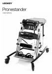
Mygo Stander
User Instructions
The Mygo Stander can be positioned in prone,
upright or supine, to allow a progressive and varied
standing therapy programme. For use by individual
or multiple children, the Mygo Stander aids and
increases functionality for children of all abilities,
with its intelligent knee supports and dynamic
footplates it can bring standing therapy to children
with fixed knee contractures of up to 25 degrees.
It’s easy and intuitive to use and simplifies the
process of getting your child into a comfortable
and secure standing position. It’s standing made
simple, whilst accommodating a broader range of
complexities. This manual shows you how you can
quickly and easily make use of all of the functions.
The instructions on the safety and maintenance of
the product will ensure that you will enjoy the use of
this product for a long time.
Contents
01
02
03
04
05
06
07
08
09
10
11
12
13
14
15
16
Intended use
Declaration of conformity
Terms of warranty
Product history record
Product Training
Safety Information
How to unpack and assemble
Fitting the Covers
Clinical setup for postural management
Frequent adjustments for daily use
Cleaning and Care Information
Daily product inspection
Annual Product Inspection
Reissuing Leckey products
Product servicing
Technical Information
1. Intended Use
The Mygo Stander is for use in prone,
supine and upright standing. The Mygo
Stander comes in 2 sizes, size 1 is for kids
aged 4-10 and size 2 is for 8-14 years,
with a maximum user weight of 50kgs
(110lbs) and 60kgs (132lbs) respectively.
2. Declaration of Conformity
James Leckey Design Ltd. as
manufacturer with sole responsibility
declares that the Leckey Mygo Stander
conforms to the requirements of the
93/42/EEC Guidelines and EN12182
Technical aids for disabled persons,
general requirements and test methods.
3. Terms of Warranty
The Warranty applies only when the
product is used according to the
specified conditions and for the intended
purposes, following all manufacturer’s
recommendations (also see general terms
of sales, delivery and payment). A two
year warranty is provided on all Leckey
manufactured products and components.
4. Product History Record
Your Leckey product is classified as
a Class 1 Medical device and as such
should only be prescribed, set up
or reissued for use by a technically
competent person who has been
trained in the use of this product.
Leckey recommend that a written record
is maintained to provide details of all
setups, reissue inspections and annual
inspections of this product.
5. Product Training Record
(Parents, Teachers & Carers)
Your Leckey product is a prescribed Class
1 Medical Device and as such Leckey
recommend that parents, teachers and
carers using the equipment should be
made aware of the following sections
of this user manual by a technically
competent person.
Section 6 Safety Information
Section 9
Clinical Setup for postural management
Section 10
Frequent adjustment for daily use
Section 11 Cleaning & Care Information
Section 12 Daily Product Inspection
Leckey recommend that a written record
is maintained of all those who have been
trained in the correct use of this product.
6 Safety Information
6.1 Always read instructions fully before
use.
6.2 Users should not be left unattended at
any time whilst using Leckey equipment.
6.3 Only use Leckey approved
components with your product. Never
modify the product in any way. Failure
to follow instructions may put the user
or carer at risk and will invalidate the
warranty on the product.
6.4 If in any doubt as to the continued safe
use of your product or if any parts should
fail, please cease using the product and
contact our customer services department
or local dealer as soon as possible.
6.5 Carry out all positional adjustments
and ensure that they are securely fastened
before you put the user into this product.
Some adjustments may require the use
of a tool which is provided with each
product. Keep all tools out of reach of
children.
6.6 When placing the user into the
standing frame, for safety reasons, always
secure the pelvic band first. The chest
and knee straps should then be fastened.
6.7 When used in the supine position it
is important to ensure the knee pads are
fastened securely. Always check the clips
are fully engaged.
6.8 Although the stander is fitted with
castors it is not a mobility device. Always
ensure that the castor brakes are locked
at all times when the frame is in use,
being adjusted or even just stored.
6.9 When adjusting the angle of the
Leckey Mygo Stander ensure that the
user and all parts of the product are well
clear of surrounding furnishings to avoid
potential collisions.
6.10 Fine positional adjustments may be
carried out safely when the user is in the
product. But it is important to support all
pads when adjusting them while the user
is in the product.
6.11 Never leave the product on a sloping
surface greater than 5 degrees. Always
remember to lock all the castors.
6.12 The product contains components
which could present a choking hazard to
small children. Always check that locking
knobs and bolts within the child’s reach
are tightened and secure at all times.
6.13 Leckey products comply with fire
safety regulations in accordance with
EN12182. However the product contains
plastic components and therefore should
be kept away from all direct sources of
heat including naked flames, cigarettes,
electric and gas heaters.
6.14 Never place hot items on the Activity
Tray as they may damage the plastic.
6.15 Clean the product regularly. Do
not use abrasive cleaners. Carry out
maintenance checks on a regular basis to
ensure your product is in good working
condition.
6.16 The product is designed for indoor
use and when not in use should be
stored in a dry place that is not subjected
to extremes of temperature. The safe
operating temperature range of the
product is +5° to +40° Celsius.
How to
unpack and
assemble
Your Mygo stander will arrive
flat in a cardboard box. Firstly
remove everything from the box
and check you have all the parts
you have ordered.
7
To assemble the product with the stander
upright, lift it up from the cross bar (a), place
vertical tubes in between the free lugs on the
chassis and line up the holes (b) (the groove
in the vertical tube should help with the
location).
Add the bolts and tighten (c). Repeat this
on the other side. Then lift up the manual
actuator to the free lugs on the cross bar and
line up the holes, then add bolts and tighten
(d).
A
A
B
B
D
C
D
7.1 Multi Tool
7.2 How to attach the
chest support
A number of adjustments will require the use
of a multi tool, which is supplied with each
product.
Remove the screw on the chest support,
place the chest support onto the metal
extrusion at the required height, replace the
screw and tighten.
7.3 How to attach the tray
receiver and tray
First of all ensure that your tray is configured
to the size of your stander.
For the Size 1 the brackets on the tray bars
should point outwards (a).
For the Size 2 the brackets on the tray bars
should point inwards (b).
If you need to change the configuration;
remove the Allen bolts (c), swap the bars
over (d) then replace the Allen bolts and
retighten (e).
Before inserting the tray receivers the clamp
plate for the height adjustment of the tray
must be moved out of the way, as it is
contained in the top of the hip pad extrusion.
To do this; loosen the knob at the top of
the hip pad (f) and push it in, this will push
the clamp plate out of the way of the tray
receiver bar. Then insert the tray receiver
bar into the top of the hip pad extrusion (g),
move it down to the required height and
retighten the knob securely.
Repeat on the opposite side. Now you can
insert your tray by inserting the tray bars into
the receivers to the required depth from the
front for prone and the back for supine then
retighten securely using knob on receiver (h).
E
A
B
C
D
G
7.4 Inserting attachment
bolt on Sandals
Insert the required attachment bolt (a)
along with the retention plate (b). Place a
rubber lid (c) on, both, the top and bottom
of the sandal. Fasten using the four screws
(d) provided. To remove or replace the
attachment bolt, reverse this process.
1
A
B
2
C
F
D
3
C
H
D
7.5 Attaching the Sandals
7.6 How to attach the
shoulder support for
supine standing
Place the sandal so that the attachment bolt
goes through the slot in the footplate. To secure,
on the underside of the footplate place the rubber
washer (a), followed by the metal washer (b) and
then the knob (c) onto the attachment bolt. To
position the sandals, simply loosen the knob
(c) under the footplate, select the position you
require and re-fasten the knob.
To attach the shoulder support to the stander,
insert the Allen bolt into the bottom hole on the
back of the chest support as shown (a). Place the
shoulder support onto the inserted Allen bolt and
secure with the two further Allen bolts supplied (b).
1
B
A
C
A
2
B
C
7.7 Attaching the headrest
for supine standing
The head support cannot be used without
the shoulder support for supine standing.
To attach the headrest place the headrest
clamp onto the shoulder support (a) and
secure using the Allen bolts provided. Then
slide the headrest stem into the receiving
bracket (b), set the height required and
secure using the hand lever (c).
A
B
C
7.8 Attaching the Knee
Straps
First of all you will need to feed the webbing
through the plastic D ring as shown in (a).
To attach the knee straps insert the plastic
clip (b) into the buckle (c) on the side of the
main knee support. Then grab the straps
ends (d) and pull firmly away from the user,
which will secure the strap around the user’s
leg. To remove the strap, simply squeeze the
tabs on the top and bottom of the plastic clip
(b) and the strap will pop off.
A
D
C
B
7.9 Attaching Sandal
Raisers
7.10 Attaching the hip belt
bracket
If sandal raisers have been ordered,
attach them by placing them onto their
corresponding building block style recesses
on the footplate (a & b). Put the sandal on
top and secure with the sandal bolt (as per
section 7.4).
Before you can attach the de-rotation hip
belt you will first of all need to attach the hip
belt bracket. To do this slide the bracket into
the receiving slots in the hip pad metalwork
(a) and secure using the Allen bolt and
washer provided (b). Repeat this on the
other side. The de-rotation hip belt does not
require hip laterals.
A
B
A
B
7.11 Attaching the hip
laterals
7.12 Attaching the
Posterior Support and
Pommel Receivers
The hip wrap around harness requires hip
laterals. To attach the hip laterals slide the
bracket into the receiving slot in the hip
pad metalwork (a) to the required width
and secure with the washer and Allen bolt
provided (b). Repeat this on the other side.
If a posterior support is required, first attach
the posterior support receiver by sliding the
bracket into the receiving slots in the hip pad
metalwork (a) and secure with the washer
and allen bolts provided (b). Repeat this on
the other side.
A
A
B
B
7.13 Attaching the
standard, flipaway &
complex chest laterals
Attaching the Pommel Receiver
Attach the pommel receiver (c) to the
bracket (d) on the hip pad, using allen bolts
provided (e).
The chest wrap around harness requires
chest laterals, either standard or flipaway.
Pull back the PU chest pad to gain access
(a). Then insert the lateral bracket together
with the angle adjustment mouldings into the
chest pad as shown (b), ensuring to insert
the plastic bosses into the chest pad slot (c).
Then secure from the outside with the Allen
bolt and washer supplied (d). Repeat this on
the other side.
A
D
E
B
C
C
7.14 Attaching the chest/
hip wrap around harness
To attach the chest/hip wrap around harness,
slide the cushions onto the PU lateral with
the flaps towards the outside of the stander
(a), feed the plastic buckle (b) through the
hole in the cover, then bring the two Velcro
fastener straps (c) around the PU lateral and
attach them to the Velcro panel as shown.
Close over the flap (d). Repeat this on the
other side.
B
C
A
D
D
C
B
7.15 Attaching the Pelvic
band
There is a different pelvic band for prone
and supine standing. In prone the pelvic
band should be attached to the user first, if
possible on a mat. The inner pelvic band is
wrapped around the user’s pelvis and then
when the user is secured into the frame (by
their feet and chest) the longer straps are
slipped through the belt bars on the hip pad
(a) and secured firmly around the user. The
safety strap with the plastic buckle and clip
should then be secured to ensure the band is
not accidentally unfastened (b).
In supine the pelvic band should stay
attached to the product. When the user is
secured into the frame (by their feet and
chest) the inner pelvic band is wrapped
around the user’s pelvis (c) and then the
longer straps (d) are slipped through the belt
bars on the hip pad (if they are not already
through) (e) and secured firmly around the
user. The safety strap with the plastic buckle
and clip should then be secured to ensure
the band is not accidentally unfastened (f).
A
E
D
B
F
Fitting
the Covers
8
8.1 Knee Support Covers
8.2 Hip Pad Cover
Wrap the covers around the knee supports
and secure by pressing down on the four
snap fasteners. There are two on either side
of the knee support (a). Repeat this on the
other knee support.
Place the cover on the hip pad in the correct
orientation. Wrap the bottom flap underneath
the hip pad and press down on the snap
fasteners to secure (a) then wrap the top
flaps of the cover over the top of the hip pad
(b).
A
A
A
A
B
8.3 Chest Pad Cover
8.4 Shoulder Support Pad
Wrap the cover over the top of the chest pad
and secure by pressing down on the snap
fasteners (a). Then wrap the bottom section
underneath and press down on these snap
fasteners to secure (b).
Follow the instructions in section 9.9 to angle
the shoulder support laterals inwards, slide
the cover over the shoulder wings (a) and
secure with the snap fasteners (b).
A
A
B
A
B
B
B
8.5 Head cushion and
cover
Place the cushion onto the head support.
Secure the central fastener (a). Bring the
lower flap under the head support (b) and
secure with the two remaining side fasteners
(c).
C
A
B
Clinical Setup
for Postural
Management
The clinical setup of the
product should be completed
by a technically and clinically
competent person who has been
trained in the use of the product.
Leckey recommend a written
record is maintained of all clinical
setups for this product.
9
9.1 Adjusting the Hip
Height
9.2 Adjusting the Chest &
Shoulder Support Height
To adjust the hip height, loosen the knobs on
either side of the stander (a), move the hip
pad to the required height and retighten the
knobs securely.
To adjust the chest height and the shoulder
support relative to the hip pad, loosen
the knob located at the back of the chest
support (a), adjust to the required height and
retighten securely.
A
A
A
9.3.1 Adjusting the knee
supports
The height, depth and lateral position
of the knee supports can be positioned
independently. To alter the height of the
knee supports, loosen the knob located at
the back of the knee post (a), adjust until
the required height has been achieved and
retighten. To alter the individual depth of the
knees, loosen the knob at the side of the
knee post (b), adjust to the required depth
and retighten securely. To alter the lateral
position of the knees, loosen the knob at
the back of the knee pad (c), adjust to the
required position and retighten securely.
A
B
C
9.3.2 Attaching the
extended knee brackets
9.4 Adjustment to
accommodate the
contracture angle
Loosen Knob (c) and remove knee support.
Slide extension bracket unto the knee
bracket and secure with white rubber
washer, silver washer, plastic spacer and
knob.
If possible, adjustment of the swinging
footplate on the Mygo stander should
be performed when the client is out
of the stander. However there may be
circumstances where it is necessary or
preferable to adjust the angle of the swinging
footplate with the client in the stander. This
process requires two competent persons;
one to make the adjustments and one to
assess the comfort of the client during the
adjustment, and is best performed with the
stander in a horizontal position.
Fix the knee supports to the extension
brackets at the required height using black
rubber washer, black washer and M6 screw.
In upright or prone standing:
Assess the client’s range of movement,
muscle tone, etc, on a plinth and determine
the optimum standing posture before
positioning the client in the stander. Position
the client in the Mygo stander. While carefully
A
Prone
Configuration
C
B
9.5 Positioning the sandals
supporting the head and shoulders, move
the client into a horizontal position. Open the
knee straps and sandal straps. Loosen the
Allen (a) bolt on both sides of the swinging
footplate ensuring the weight of the user’s
knees are supported by a carer, adjust the
angle of the swinging footplate as necessary,
always taking care to assess the client’s
comfort, and retighten the bolts securely.
Then secure the knee straps and sandal
straps. Return the client to prone standing
position.
Each sandal is attached to the individual
footplate with a single fixing bolt. The
footplate is encapsulated in rubber to ensure
the sandals do not slide when secured.
To position the user’s feet in the sandals
secure the Velcro straps provided so the foot
is held in place. The straps should be over
the bridge of the foot and over the toes. The
front strap can be fed through one of two
slots on either side of the sandals, depending
on the size of the user’s feet (2).
In supine standing:
Assess the client’s range of movement,
muscles tone, etc, on a plinth and determine
the optimum standing posture before
positioning the client in the stander. Position
the client in the Mygo stander and move it
into a horizontal position. Open the knee
straps and sandal straps. Loosen the
Allen bolt (a) on both sides of the swinging
footplate ensuring the weight of the user’s
knees are supported by a carer, adjust the
angle of the swinging footplate as necessary,
always taking care to assess the client’s
comfort, and retighten the bolts securely.
Then secure the knee straps and sandal
straps. Return the stander to preferred
supine standing angle.
If the child is wearing sandals or light
footwear check the straps to make sure
the webbing does not irritate the skin.
B
Supine
Configuration
1
2
9.6 Secondary Footplate
Angle
9.7 Adjusting the Hip
Laterals
To set the angle to accommodate plantarflexion or dorsi-flexion, simply loosen the
Allen bolt located by the knee post to the
inside of the footplate (a), place in the
required position and then retighten the bolt
securely. 10° of flexion is accommodated in
each direction.
To set the width of the hip laterals, loosen
the Allen bolts at the back of the hip pad (a),
adjust to desired width and retighten.
A
A
9.8 Adjusting the standard,
complex and flipaway chest
lateral supports
To adjust the height and angle of the lateral
supports, loosen the Allen bolt (a), adjust
to the required width, height and angle and
retighten securely.
Complex laterals
The complex laterals can also be angled to
allow the pad to contour to the user’s shape.
To adjust loosen the screw (b) at the centre
of the pad, angle the pad to the required
position and retighten the screw. The laterals
can be flipped away to aid transfer, by
pulling the pin (c) at the back and rotating
the support out of the way.
B
C
A
9.9 Shoulder Support
9.10 Headrest
To adjust the angle of the shoulder support
laterals, loosen the Allen bolt screw (a), move
laterals to required angle and retighten.
To adjust the height, depth and angle of the
headrest, loosen the hand knobs (a) and
when set to the desired position retighten the
knobs. Do not remove the headrest while the
user is in the stander.
A
A
9.11 Attaching and
adjusting the posterior
support and pommel
To adjust the posterior support, loosen
receiver allen bolt (a) slide the outside bars
into the receivers (b) to the required depth
and tighten (a).
B
A
C
E
D
9.12 Increase Tray
Adjustment
Attaching and adjusting the pommel
To attach the pommel, loosen the receiver
allen bolt (c), slide the pommel into the
receiver (d) and tighten at the required depth.
The height can also be adjusted using the
allen bolt (e) at the back of the pommel.
To increase the depth adjustment of the
tray, reposition the tray bars further back.
To do this, unscrew the Allen bolts holding
the tray bars on (a), move the bars to the
holes further back (b) replace the bolts and
retighten all bolts securely.
A
B
C
D
E
9.13 Attaching and
Adjusting the Tray
Grab Rails
To attach the grab rails firstly remove tray
bars. To do this, unscrew the Allen bolts
holding the tray bars on (a) (note positioning
holes used). Place down spacer plate (b),
then slotted plate (c). Secure, with tray bar in
original holes, using supplied longer screws
(d). Repeat this on the other side.
A
B
C
9.14 Tray Insert Changes
Attach the grab rail receiving brackets (e) as
shown. Place the grab rail into the receiving
brackets. Adjust to the required height and
tighten (f) on both sides.
To swap out different inserts for tray, firstly,
turn the tray upside down, then remove Allen
bolts holding in the current insert (a) and
tray protection pad (if there is one). Remove
old insert (b) and replace with new one and
secure to tray and add tray protection pad
using same Allen bolts.
E
A
B
F
Frequent
Adjustments
for Daily Use
Parents and carers should be
shown how to make frequent
adjustments and made aware
of the safety checks in section
6 by a technically and clinically
competent person who has been
trained in the use of the product.
Leckey recommend that a written
record is maintained of all parent
and carers who have been trained
in the use of this product.
10
10.1 Transferring the user
into and out of the Stander
10.2 Setting the Stander
Angle
Before transferring the child into the stander
carry out the daily product inspection as
outlined in section 12 of this user manual.
We would recommend that users are never
transferred straight from seating to standing
without preparation and stretching. This
is best done in a lying position whilst on a
mat but can be carried out in a wheelchair
or seating system if required. Before
transferring the child into the product lock
all the castors, ensuring that they are facing
outwards to maximise product stability. Make
sure the straps on the chest harness, pelvic
band, knee straps and sandals are released
and out of the way to facilitate transfer.
Whether used in supine or prone the frame
angle can be easily adjusted by pulling and
twisting the safety lock (a) and turning the
handle (b) until the desired angle has been
achieved (the angle can be read from the
cross bar (c). Turn the handle clockwise to
bring it upright and anti-clockwise to bring it
towards horizontal. The stander can adjust
from vertical (0°) through to 10° off horizontal
(80°). This can be done whilst the child in
the product.
Ensure that the product and user are
away from surrounding furnishings to
prevent possible collisions when adjusting
the angle.
C
A
B
10.3 Positioning the
Sandals
10.4 Knee Straps
To position the user’s feet in the sandals,
secure the Velcro straps provided so the foot
is held in place. The straps should be placed
over the bridge of the foot over the toes.
To attach the knee straps insert the plastic
clip (a) into the buckle (b) on the side of the
main knee support. Then grab the straps
ends (c) and pull firmly away from the user,
which will secure the strap around the user’s
leg. To remove the strap, simply squeeze the
tabs on the top and bottom of the plastic clip
and the strap will pop off.
The front strap can be fed through one
of two slots on either side of the sandals,
depending on the size of the user’s feet (2).
If the child is wearing sandals or light
footwear check the straps to make sure
the webbing does not irritate the skin.
Always check with your therapist as to the
correct tensioning of the straps for your
child as the kneecap is a sensitive area
and too much force could cause injury.
1
B
A
2
C
10.5 Positioning and
attaching the Pelvic band
There is a different pelvic band for prone
and supine standing. In prone the pelvic
band should be attached to the user first, if
possible on a mat. The inner pelvic band is
wrapped around the user’s pelvis and then
when the user is secured into the frame (by
their feet and chest) the longer straps are
slipped through the belt bars on the hip pad
(a) and secured firmly around the user. The
safety strap with the plastic buckle and clip
should then be secured to ensure the band is
not accidentally unfastened (b).
In supine the pelvic band should stay
attached to the product. When the user is
secured into the frame (by their feet and
chest) the inner pelvic band is wrapped
around the user’s pelvis (c) and then the
longer straps (d) are slipped through the belt
bars on the hip pad (if they are not already
through) (e) and secured firmly around the
user. The safety strap with the plastic buckle
and clip should then be secured to ensure
the band is not accidentally unfastened (f).
A
E
C
D
B
F
10.6 Wrap Around Lateral
Harness
To open the wrap around chest harness,
simply unclip the side buckle (a) and open.
Reverse the process when placing the user
back in the product, ensuring to secure the
straps firmly around the user. The safety
strap with the plastic buckle and clip should
then be secured to ensure the band is not
accidentally unfastened (a).
Always secure the chest and hip support
harnesses (and knees straps when used
in supine) first before making other
adjustments.
Always make sure the plastic buckles are
fully engaged.
A
10.7 Tray Adjustment
To insert and adjust the depth of the tray,
loosen the knobs on the back of both tray
receivers (a), slide the tray in to the required
depth, and retighten. To increase the depth
adjustment further, see 9.12.
To adjust the angle of the tray, loosen the
plastic handle in the centre of both the tray
receivers (b), set the tray to the required
angle and tighten the plastic handles again
securely.
To adjust the tray height, loosen the knobs
at the top of the hip pad (c) adjust receivers
to required height and retighten, ensuring the
tray is at a level height by matching the scale
on the side of the tray receiver bars.
Never use the tray to steer or push the
chair.
Do not place hot objects (hotter than 40°
Celsius) on the tray.
Please note that the tray is for the use of
the user only.
Do not lean or place heavy objects
(heavier than 8kgs/17.6lbs) on the tray.
A
B
C
11 Cleaning & Care
Information
How to Maintain
When cleaning the product we recommend
that you use only warm water and a
nonabrasive detergent. Never use organic
solvents or dry cleaning fluids.
Upholstery and fabrics
1. The upholstery and fabrics can be
removed and machine washed and tumble
dried at a low setting. The standard covers
can be washed at 40 degrees Celsius and
the Infection Control covers at 90 degrees
Celsius. Please remove the foam before
washing the head support, posterior support
and pommel covers. All other soft upholstery
can be placed directly in the washing
machine.
2. If the upholstery is to be cleaned in-situ,
the best cleaning method is a ‘wipe & dry’
technique.
3. Staining should be removed as quickly
as possible with absorbent cloth, towels or
a sponge. Routine soap and warm water
sponging is effective for ordinary soiling
and minor spills. Be careful not to over wet
the fabric, as this will cause the staining to
spread.
4. Antiseptic cleaning agents can be used
on more stubborn stains. These may require
a safe solvent such as Isopropyl Alcohol or
Mineral Spirit. A half cup of household bleach
to 5 litres of water can also be used as a
useful disinfectant.
5. Always ensure the product is dry before
use.
Metal and plastic components
1. Soap and water or antibacterial spray can
be used for daily cleaning.
2. For deep cleaning a low pressure steam
cleaner can be used.
3. Do not use solvents to clean plastic or
metal components.
4. Make sure the product is dry before use.
12 Daily Product Inspection
(Therapists, Parents & Carers)
We recommend that daily visual checks of
the equipment are carried out by therapists,
carers or parents to ensure the product is
safe for use. The recommend daily checks
are detailed below.
1. Ensure all adjustment knobs and bolts are
in place and secure.
2. Check all upholstery for signs of wear and
tear.
3. Check all wheels are moving freely and
lock securely.
4. Check all Velcro strips and brush fluff to
ensure straps secure firmly.
If in any doubt to the continued safe
use of your Leckey product or if any
parts should fail, please cease using
the product and contact our customer
services department or your local dealer
as soon as possible.
13 Annual Product
Inspection
(Therapist, Technician, Leckey Product
Advisor, Dealer)
Leckey recommend that each product should
be subject to a detailed inspection at least
once a year and every time the product is
reissued for use. This inspection should
be carried out by a technically competent
person who has been trained in the use of
the product and should include the following
checks as a minimum requirement.
1. Check all knobs, nuts, bolts and plastic
buckles are in place, replacing any missing
items. Paying particular attention to the
following items;
> Buckles and Velcro on pelvic bands, knee
straps and wrap around lateral harnesses
> Hip, knee and chest height adjust and lock
securely
> Contracture angle and secondary footplate
angle adjust and lock securely
> Knee supports depth and width adjust and
lock securely
> Head support locks securely
2. Lift the base to check each wheel
individually. Make sure they are moving freely
and remove any dirt from the rubber wheels.
Check that the brakes lock the wheels
securely.
3. Visually check the structure of the product
ensuring there are no signs of fatigue or
cracking around the welds.
4. Visually check the plastic parts of the
product ensuring there are no signs of
fatigue or cracking.
5. Leckey recommend that a written record is
maintained of all annual product inspections.
If in any doubt to the continued safe
use of your Leckey product or if any
parts should fail, please cease using
the product and contact our customer
services department or your local dealer
as soon as possible.
14 Re-issuing Leckey
Products
15 Product Servicing
Most Leckey products are assessed and
ordered to meet the needs of an individual
user. Before reissuing a product we
recommend that the therapist prescribing
the product has carried out an equipment
compatibility check for the new user and has
ensured that the product being re-issued
contains no modifications or special
attachments.
Servicing of all Leckey products should only
be carried out by technically competent
persons who have been trained in the use of
the product.
A detailed technical inspection should be
carried on the product prior to re-issuing.
This should be carried out by a technically
competent person who has been trained in
the use and inspection of the product. Please
refer to section 13 for the required checks to
be carried out.
Ensure the product has been cleaned
thoroughly in accordance with section 11 of
this manual.
Ensure a copy of the user manual is supplied
with the product. A copy can be downloaded
from our website www.leckey.com.
Leckey recommend that a written record is
maintained of all product inspections carried
out during the reissue of the product.
If in any doubt to the continued safe use of
your Leckey product or if any parts should
fail, please cease using the product and
contact our customer service department or
your local dealer as soon as possible.
In the UK & ROI please contact the Leckey
Service Centre on UK 0800 318265 or ROI
1800 626020 and our customer service
department will be delighted to assist you
with your servicing requirements.
All international service enquiries should be
directed to the appropriate Leckey distributor
who will be delighted to assist you. For
further information on Leckey distributors
please visit our website www.leckey.com.
16 Technical Data
Size
1
2
Age (Years Approx)
4 - 10
8 - 14
mm
inches
mm
inches
User height
min
max
1080
1450
42.5
57.1
1350
1750
53.1
66.9
Max user weight
50kgs
110lbs
60kgs
132lbs
Chest support height (footplate to armpit)
min
max
760
1080
29.9
42.5
980
1300
38.6
51.2
Chest width (distance between laterals)
min
max
160
280
6.3
11.0
200
320
7.9
12.6
Hip support height (footplate to mid
buttocks)
min
max
460
730
18.1
28.7
620
875
24.4
34.4
Hip width (distance between hip guides)
min
max
220
330
8.7
13.0
280
390
11.0
15.4
Footplate angle
Plantarflexion
Dorsiflexion
10°
10°
10°
10°
Max knee contracture accommodated
25°
25°
Tray height range (from top of hip pad)
0 - 150
Tray angle adjustment
Prone
Supine
45°
45°
Product weight
22kgs
Product angle range
Prone
Supine
0° to 80°
0° to 80°
Stander footprint
Length
Width
978
630
0-6
0 - 150
0-6
45°
45°
48lbs
25kgs
55lbs
0° to 80°
0° to 80°
38.5
24.8
1130
650
44.5
25.6
Product and accessory
codes
Code
143-1600
143-2600
Mygo Stander
Size 1 stander - with manual angle adjustment, PU chest pad, PU hip
pad, PU knee supports, two piece footplate
Size 2 stander - with manual angle adjustment, PU chest pad, PU hip
pad, PU knee supports, two piece footplate
143-1770-09
143-1770-08
143-1770-07
143-2770-09
143-2770-08
143-2770-07
Size 1 Cover
pad covers)
Size 1 Cover
pad covers)
Size 1 Cover
pad covers)
Size 2 Cover
pad covers)
Size 2 Cover
pad covers)
Size 2 Cover
pad covers)
143-1638
143-1768-09
143-1768-08
143-1768-07
Shoulder
Shoulder
Shoulder
Shoulder
pad
pad cover - pink
pad cover - blue
pad cover - orange
120-859
143-1787
137-800-05
137-699-05
143-1662
Headrest
Headrest
Headrest
Headrest
Headrest
hardware
cushion and cover - infection control (black)
cushion and cover (black)
cushion and cover (black) (includes hardware)
- infection control (black) (include hardware)
143-1619
143-1675
Chest lateral hardware only (pair)
Flipaway laterals hardware (pair)
143-1673
143-1674
Complex lateral vertical - right hand side (single with cover)
Complex lateral vertical - left hand side (single with cover)
143-1780-09
143-1780-08
143-1780-07
143-1775-14
143-2780-09
143-2780-08
143-2780-07
143-2775-14
143-3780-09
143-3780-08
143-3780-07
143-3775-14
Size
Size
Size
Size
Size
Size
Size
Size
Size
Size
Size
Size
143-1798-09
Size 1 prone derotation hip belt - pink (includes hardware)
1
1
1
1
2
2
2
2
3
3
3
3
pack - pink (contains chest pad, hip pad and knee
pack - blue (contains chest pad, hip pad and knee
pack - orange (contains chest pad, hip pad and knee
pack - pink (contains chest pad, hip pad and knee
pack - blue (contains chest pad, hip pad and knee
pack - orange (contains chest pad, hip pad and knee
chest/hip
chest/hip
chest/hip
chest/hip
chest/hip
chest/hip
chest/hip
chest/hip
chest/hip
chest/hip
chest/hip
chest/hip
wraparound
wraparound
wraparound
wraparound
wraparound
wraparound
wraparound
wraparound
wraparound
wraparound
wraparound
wraparound
harness
harness
harness
harness
harness
harness
harness
harness
harness
harness
harness
harness
-
pink
blue
orange
infection control (black)
pink
blue
orange
infection control (black)
pink
blue
orange
infection control (black)
143-1798-08
143-1798-07
143-2798-09
143-2798-08
143-2798-07
143-1783-09
143-1783-08
143-2783-07 143-2783-09
143-2783-08
143-2783-07
143-1663
Size 1 prone derotation hip belt - blue (includes hardware)
Size 1 prone derotation hip belt - orange (includes hardware)
Size 2 prone derotation hip belt - pink (includes hardware)
Size 2 prone derotation hip belt - blue (includes hardware)
Size 2 prone derotation hip belt - orange (includes hardware)
Size 1 supine derotation hip belt - pink (includes hardware)
Size 1 supine derotation hip belt - blue (includes hardware)
Size 1 supine derotation hip belt - orange (includes hardware)
Size 2 supine derotation hip belt - pink (includes hardware)
Size 2 supine derotation hip belt - blue (includes hardware)
Size 2 supine derotation hip belt - orange (includes hardware)
Hip lateral hardware only (pair)
143-1776-09
143-1776-08
143-1776-07
143-1776-14
143-2776-09
143-2776-08
143-2776-07
143-2776-14
Size
Size
Size
Size
Size
Size
Size
Size
143-1778-09
143-1778-08
143-1778-07
143-1690
143-1609
143-1633
143-1610
143-2609
143-2633
143-2610
Split knee straps - pink - fits both sizes
Split knee straps - blue - fits both sizes
Split knee straps - orange - fits both sizes
Extended knee brackets
Size 1 Mygo stander tray
Size 1 Mygo stander tray with bowl insert
Size 1 Mygo stander tray with clear insert
Size 2 Mygo stander tray
Size 2 Mygo stander tray with bowl insert
Size 2 Mygo stander tray with clear insert
143-1624
143-2624
Size 1 posterior support and pommel (fits size 1 stander only)
Size 2 posterior support and pommel (fits size 2 stander only)
143-1790-09
143-1790-08
143-1790-07
143-1790-14
143-1792-09
143-1792-08
143-1792-07
143-1792-14
Posterior support cover - pink
Posterior support cover - blue
Posterior support cover - orange
Posterior support cover - infection control
Pommel support cover - pink
Pommel support cover - blue
Pommel support cover - orange
Pommel support cover - infection control
152-1600
152-2600
152-3600
Sandals Size 1
Sandals Size 2
Sandals Size 3
143-1615
143-1649
Sandal raisers
Grab rail
1
1
1
1
2
2
2
2
basic
basic
basic
basic
basic
basic
basic
basic
knee
knee
knee
knee
knee
knee
knee
knee
straps
straps
straps
straps
straps
straps
straps
straps
-
pink
blue
orange
infection control (black)
pink
blue
orange
infection control (black)
Leckey
19 Ballinderry Road
Lisburn
BT28 2SA
Northern Ireland
United Kingdom
T: 028 9260 0750
E:[email protected]
W:www.leckey.com
24 hour postural
care for babies,
kids & adults.
Sleeping, Sitting,
Standing, Walking,
Moving, Bathing,
Toileting.
LS262-04