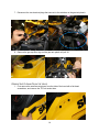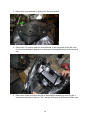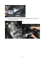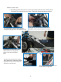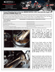
1
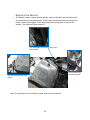
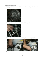
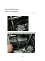
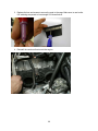
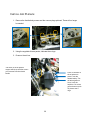
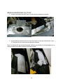
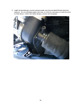
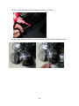
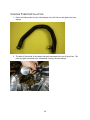
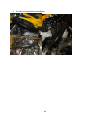
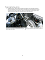
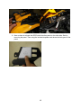
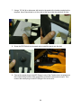
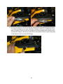
XP/XM 600/800 ETEC Turbo System Installation Manual V2.0 TABLE OF CONTENTS Introduction ................................................................................................................................1 Tools Needed: ...............................................................................................................................3 Preparation ...................................................................................................................................4 XP Only Prep ............................................................................................................................4 Remove Body Panels ..............................................................................................................4 Remove Front Air Plenum .....................................................................................................10 XM Only Prep .........................................................................................................................12 Remove Body Panels ............................................................................................................12 Remove Air Plenum From the Hood .......................................................................................14 Remove Gas Tank ....................................................................................................................18 Remove Stock Muffler .............................................................................................................20 Remove Stock Air box..............................................................................................................21 Install Air Plenum .......................................................................................................................22 Aerocharger Installation ...............................................................................................................32 Charge Tube Installation ..............................................................................................................39 Fuel Line Installation ...................................................................................................................41 Electronics and Boost Lines ..........................................................................................................42 Power Harness Installation ........................................................................................................42 Solenoid Valve Installation .......................................................................................................43 Aero-Commander Installation....................................................................................................44 Gauge Installation ....................................................................................................................46 XP Gauge Installation ...........................................................................................................46 XM Gauge Installation ..........................................................................................................48 Rave Valve Installation .............................................................................................................53 Putting the Snowmobile back together ...........................................................................................54 Reconnect The Gas Tank ..........................................................................................................54 XP Replace Panels ...................................................................................................................57 XM Replace Panels ..................................................................................................................61 Venting the Side Panels ................................................................................................................65 XP Vents .................................................................................. Error! Bookmark not defined. XM Vents ................................................................................. Error! Bookmark not defined. Air/Snow Intercooler Installation ..................................................... Error! Bookmark not defined. Appendix....................................................................................................................................67 Innovate MTX-L Error Codes....................................................................................................67 Skidoo Pressure Line Diagram...................................................................................................68 Fuel ...........................................................................................................................................70 Clutching...................................................................................................................................71 Reeds ........................................................................................................................................72 INTRODUCTION Congratulations on your purchase of the Aerocharger Turbo system for the Skidoo Etec Snowmobile. You are now the owner of the most powerful, reliable, and technologically advanced turbocharger in the world. With your new intercooled turbocharger and fuel system installed, you will experience substantial performance gains. Not only will you get amazing performance but our unique system which combines VATN technology (Variable Area Turbine Nozzle) and our nearly frictionless, non-flooded ceramic ball bearing design will provide you with our famous zero turbo-lag. This system is made and assembled by Aerocharger LLC. We manufacture turbo systems with a passion. The installation of this kit consists of: 1. Installation of the turbo system hardware 2. Installing the fuel control electronics 3. Tuning the clutching Note: Before getting started, refer to the Packing List and identify all the components of your turbo system. This will also aid in the installation process. Note: This Installation guide covers all Etec models including 600 engines, 800 engines, XP models, XM models, Non Intercooled Systems, Air/Snow Intercooled Systems. Read the entire manual before installing and skip sections the do not apply to your system. WARNING! Installation of the turbo system is not for the mechanically challenged! If you are uncomfortable performing any of the tasks outlined in this manual, please refer to trained professionals at your local performance shop. If you are performing the installation of this system, it is suggested that you read this ENTIRE manual prior to proceeding with the installation. It is also suggested that you review each section as you progress to ensure everything is installed correctly. WARNING! Do NOT hit the rev limiter. It will lead to detonation and you will damage your engine. 1 WARNING! This system is designed for use on a STOCK 600/800 Rev-XP only! WARNING: If your Rev-XP has been modified, consult Aerocharger (913.541.0200) before proceeding. This Turbo system is intended for use on a STOCK, well-maintained 600/800 Rev-XP with a strong running, well-maintained engine. Installation of this kit on brand-new snowmobiles with very few miles/hours on them is NOT recommended. New engines require specific break-in procedures that do not include adding forced induction! If your snowmobile is brand new, consult your local dealership and owner’s manual to determine proper break-in procedures BEFORE continuing with this installation. Failure to do so may result in significant internal engine damage. AEROCHARGER WILL NOT BE HELD RESPONSIBLE FOR DAMAGE TO VEHICLES POWERTRAIN. Aerocharger is not responsible for ECU tuning/ programming on 600/800 Rev-XPs that were not stock before the installation of this turbo kit. WARNING: For best performance and reliability always use minimum 91-octane non-ethanol fuels and listen for signs of detonation. IF DETONATION SHOULD OCCUR OR IF YOU ARE UNSURE IF YOU ARE HEARING DETONATION, DECREASE THROTTLE APPLICATION IMMEDIATELY and consult Aerocharger staff (913.541.0200). Detonation should NOT be an issue with this kit provided if it is installed correctly, though OEM factory shipped engine and parts inconsistencies are possible on any new vehicle. Note: Aerocharger holds no responsibility for any powertrain damage that results from misuse of this turbo system! Note: Read and understand ALL safety and technical precautions in this manual before proceeding. Failure to comply with the instructions in this manual could result in personal injury, property damage, voiding your warranty, and/or inconsistent/poor performance from the turbocharger system. Contact Aerocharger for any questions or concerns. Do NOT let any debris (hard or soft) enter the existing air intakes or exhaust ports during installation of this turbo kit. Do NOT use any silicone sealants under any circumstances. Doing so can result in F.O.D. (Foreign Object Damage) to the turbo. This will void your warranty. 2 TOOLS NEEDED: 1. Metric socket and wrench set (7mm-17mm) 2. T27 torx wrench 3. Stubby Phillips head screwdriver 4. Long Phillips head screwdriver 5. 2.5” hole saw 6. 6”-8” 3/8” socket extension 7. Spring tool 8. Torque wrench 9. 4mm Allen wrench 10. 1.5” Hole Saw 11. 7/8” Wrench 12. Razor Blade 3 PREPARATION XP ONLY PREP Only use this section of the manual if you have a XP model. If you have a XM model then you should skip to the next section. REMOVE BODY PANELS 1. Remove the left and right side panels. 2. Remove the nose panel. 4 3. Remove the gauge panel by unscrewing the 5 T27 torx screws, the two on each side and one in the front 5 4. Disconnect the Gauge panel electronics. Press with your thumb as shown in the picture and pull the clip off. Squeeze with your thumb and pull the clip off. Pull out both of the headlight clips Press with your thumb as shown in the picture and pull the clip off. 6 Push up and out with your thumb as shown. 5. Remove the headlights: there are two T27 torx screws under the windscreen holding them on. Do not discard hardware, as they will be reused later. 6. Remove the seat. 7 7. Remove the gas tank panel. First, unscrew the gas cap and remove the threaded plastic retainer. There are also two T27 torx screws toward the front that need to be removed. 8 8. Disconnect the electrical connections from the gas tank panel. There may be fewer connections depending on the sled model. 9 REMOVE FRONT AIR PLENUM 1. Unscrew the T27 torx screws connected to the gas tank. 2. Use a 7 mm socket to remove the coolant tank from the front of the air plenum and disconnect hoses. Note: this is not required on sleds with a 600cc engines. 3. Pull off the Velcro strap on the bottom of the plenum. 10 4. Loosen the hose clamp on the top of the air box then remove the top section of the plenum. 11 XM ONLY PREP Only use this section of the manual if you have a XM model. If you have a XP model then you should skip to the next section. REMOVE BODY PANELS 1. Start by taking the side panels off the sled 2. Remove the bolts holding on the hood assembly using a T27 Torx to remove the 2 bolts under the gauge cluster and the 2 bolts on either side of the hood. 3. There is also a Velcro strap holding the hood assembly to the chasis that needs to be unstrapped. Then loosen the velocity tube on the clutch side of the sled connecting the two air plenums together with a flat head screwdriver. 12 4. Disconnect the main electrical plugs from the back of the gauge cluster and the air temperature sensor on the velocity tube connecting the two air plenums. 5. At this point you can remove the hood from the sled by puling forward and up. 6. Remove the 2 T27 bolts on either side of the gas tank plastic connecting it to the gas tank. 13 7. Disconnect the two electrical plugs that connect to the switches on the gas tank plastic. 8. Remove the gas cap filler ring and the gas tank plastic will pull off. REMOVE AIR PLENUM FROM THE HOOD 1. First remove the small accent pieces from the side of the hood with a flat head screwdriver, and remove the T27 bolt under them. 14 2. Remove the 2 T27 Bolts on the underside of the hood toward the front. At this point the headlights, gauge cluster, and air plenum will come free of the hood plastic. 15 3. Remove the snow deflector by pulling it off. No tools needed. 4. Remove the T27 screws under the snow deflector so that the gauge cluster will come free from the headlights. Make sure to disconnect the headlight electrical connectors as well. 5. Remove the Intake vents from the side of the headlight assembly by removing the 2 screws that hold each of them on. The 2 screws are located on the bottom of each vent. 16 6. Remove the 2 bolts holding the headlights on. The headlights and glove box will come free of the stock air plenum. 17 REMOVE GAS TANK 1. Unbolt the gas tank: there are two 13 mm nuts on either side of the seat. There are two 10mm bolts at the handle bars and 2 more 10mm bolts connecting support members. Two 10mm bolts connect the frame members running along the gas tank to the handle bar neck. There are two vertical members attached at the handle bar neck connected with two 10mm bolts. Remove the four 10mm bolts and the frame members over the gas tank will be loose from the handlebar neck. On either side of the gas tank, midway down, there are two 13mm nuts covered by panels that snap off. Pull outward on the panels to remove them. Use a 13mm ratchet to remove the nuts on both sides of the gas tank. 18 2. Remove gas tank vent line. 3. Remove fuel lines and electrical connectors from the fuel pump assembly. 4. Slide the fuel tank away from the airbox. 19 REMOVE STOCK MUFFLER 1. The Muffler is held on with 4 exhaust springs - one on both sides near the bottom and two connecting it to the exhaust pipe. There is also a temperature sensor on top of the muffler. Remove this using a 17mm wrench and use a spring puller to remove the springs. The muffler will easily come off. Two spring tabs connect the muffler to the exhaust pipe. The clip toward the front of the muffler. The clip toward the rear of the muffler. Note: The temp sensor in the muffler is fragile, take care not to break it. 20 REMOVE STOCK AIR BOX 1. Remove the intake air temperature sensor from the airbox tube using a flat head screwdriver to pry up the two retainers. Leave it connected to the wiring harness and move it aside. 2. Loosen the two hose clamps holding the airbox onto the throttle bodies using a long Phillips head screwdriver. 3. Remove the airbox. 21 REMOVE SECONDARY CVT 1. Using the clutch tool provided with the sled, open the secondary clutch and remove the belt. 2. Using a 10mm wrench, remove the nuts from the bearing retainer. 3. Use a 16mm socket and remove the bolt holding the chain gear to jack shaft. 4. 22 5. Use a non-marring rod or the Ski-doo gear retaining tool to drive out the jackshaft. If using a rod, leave it in place to hold the gear and spacer after the jackshaft is removed. 6. Remove the jackshaft bearing support. There are four 13mm nuts holding it in place. 23 INSTALL REED PEDALS REMOVE STOCK COMPONENTS 1. Use a long, straight slot screwdriver to loosen hose the clamps holding the throttle bodies onto the reed boots. Then remove the throttle bodies, do not disconnect the throttle cable. 2. Use a 8mm socket to remove the 12 bolts holding the reed cage boots in place. 24 INSTALL REED PEDALS We have included 4 outer reed pedals that are designed for turbo Etec engines. They replace the stock outer reeds. The inner reeds do not suffer any additional wear and tear from the turbo system so they do not need to be replaced. 1. Remove the reed cage and unscrew the stock outer reeds. They are the reeds on the case side of the reed cage and have a solid bar holding them to the cage. 2. With the stock outer reeds removed install the new reeds included with your system. The reeds have a concave side and a convex side. If they are not installed correctly you will experience poor throttle response. In case you cannot see which side is concave then there is a notch in the corner of the reed pedals. This notch goes in the upper right part of the cage as pictured below. 25 3. Replace the bar and screws to secure the reed to the cage. Make sure to use Loctite 641 retaining compound or low strength 222 thread locker. 4. Reinstall the reeds and boots onto the engine. 26 REASSEMBLE TO INSTALL THE AIR PLENUM 1. Re-attach the throttle bodies and tighten the hose clamps. 2. Reattach the driveshaft support arm. Torque the bottom bolts to 18 ft-lbs. Torque the top bolt to 124 in-lbs. 27 REINSTALL THE SECONDARY CLUTCH 1. Put the driveshaft back in its original location. Do not drop the gear that it slides into or you will have to open the chain case to get it out. When installing the jackshaft, you need to have the bearing retainer started before completely sliding in the shaft. 2. Thread the bolt and washer into the driveshaft, and tighten it down with a torque wrench. Torque the bolt to 38 ft-lbs. Reinstall the rubber cap. 3. Torque the nuts on the bearing retainer flange to 133 in-lbs. 28 4. Reinstall the belt and remove the compression tool from the CVT driven. 29 INSTALL AIR PLENUM 1. Remove the throttle body screws and the vacuum plugs pictured. These will no longer be needed. 2. Using the supplied silicone packet, lubricate the o-rings. 3. Press on the air box. The holes on the air plenum support will line up with the screws you removed from the throttle bodies. Press on the back of the air plenum to press it onto the throttle bodies. This will take significant force. It may be helpful to use a heat gun and warm up the air plenum and orings. 30 4. Using the longer screws provided, attach the air box to the throttle body. 5. Instal the spring on the bottom of the air plenum. The spring hooks onto the bracket that holes the clutch shield in place. 31 AEROCHARGER INSTALLATION 1. Using the provided cover and rivets, cover the factory exhaust hole location. 2. Use the pattern included in the kit to mark the location of the new exhaust hole. Use a 2.5” Hole saw to cut a hole where the template indicates. Note: The XM and XP use the same template, however you will have to cut the template out on the line marked for the XM to locate the XM exhaust hole. 32 3. Seat the cradle in its place. The holes in the base will correspond with the stock rivets. (Note: Old muffler design is shown in photograph) 4. Bolt the cradle to the frame using the stainless steel washers and four nuts and bolts supplied in the kit on the other side of the foot well. 5. Install the ceramic-coated heat shield and exhaust wrap onto the turbine housing of the Aerocharger. 33 6. Install the Aerocharger onto the exhaust cradle using the provided M8 bolts and lockwashers. Do not completely tighten the bolts, as it may be necessary to rotate the turbo for final fitment. (Note: Old muffler design is shown in photograph) 34 7. Remove your expansion pipe and check for any welding debris. We found mig wire on our pipe and were able to remove it using a sanding wheel. After inspection make sure to blow out any debris. 8. Bolt the turbine inlet pipe to the turbo, using the M10 flange bolts provided in the kit. Use the original graphite gasket on the exhaust pipe. If gasket is damaged, replace with a new gasket. 35 Put the inlet pipe on as shown in the picture. Remember to put the gasket included with the kit inbetween the turbine inlet pipe and the Aerocharger. 9. Tighten the bolts on the Turbo. Tighten the Turbine Outlet bolts using a 13mm open ended wrench. Tighten the four turbine inlet bolts using a 15mm wrench. 10. Using a spring tool, install two springs per side onto the connection between the turbine inlet pipe and the expansion pipe. 11. Using a 16mm wrench, reinstall the temperature sensor into the bung on the muffler. The sensor needs to be oriented as pictured to prevent damage to the sensor. 36 12. Remove the brass pipe plug shown. 13. Add two bottle of Aerocharger Oil. 37 14. Put LocTite 262(Red) on the plug and then torque to 35 in-lbs. 15. After the turbocharger has its oil, press the dome air filter over the compressor inlet. 38 CHARGE TUBE INSTALLATION 1. Route the Charge tube from the turbocharger to the Air Plenum and tighten the hose clamps. 2. The blow off valve side of the charge tube gets connected to the top of the air box. The other end gets connected to the compressor outlet on the Aerocharger. 39 3. The tube is routed behind the headlights. 40 FUEL L INE INSTALLATION 1. Install the fuel line. The fuel line should be routed right in front of the ECU and behind the chasis members. If the fuel line seems to short then route it more directly. Be sure to check all along the line to make sure it will not rub excessively on anything and rupture. Also be sure all of the fittings are connected securely and not broken. The short legs of the line get installed between the gas tank fuel line and the ECU. 41 The long leg of the fuel line gets screwed onto the fuel rail. ELECTRONICS AND BOOST LINES POWER HARNESS INSTALLATION 1. The wiring harness uses the extra fuse block on the oil tank to supply power to our electronics. Ground Fuse Block Connectors for Aerocommander and AFR Gauge 2. Insert the power wire into the open fuse block and connect the ground the the stock grounding bolt located behind the mag side footwell. 3. Insert the fuse included with the wiring into the fuse block, and route the wiring harness up to the Aercommander and AFR Gauge. Either plug will work for both devices 42 SOLENOID VALVE INSTALLATION 1. The solenoid valve comes pre assembled with lines marked for their locations. 2. Connect the lines marked to manifold to the barbs on the throttle bodies, zip tie the solenoid valve the chasis. 3. The line that is marked “Line to Aerocommander” is connected to the barb on the blue line of the Aerocommander. Photo for this step is in the AeroCommander Installation Section. 43 AEROCOMMANDER INSTALLATION Note: The basic installation of the Aerocommander is the same for the XM and XP models. The photographs show the installation on a XP model. The basic routing of the wires and connectors is the same for both. 1. With the Aerocommander near the handlebars, feed the wires down the steering shaft into the engine bay. Then connect the connectors to their appropriate locations. Run the electrical harness through the handlebars and into the sled. This is the default mounting position for the AeroCommander. Unplug the ignition coil plug, this is directly across from the fuel rail and is pictured above. The AeroCommander harness gets connected inline at this plug. 44 Connect the long leg of the harness to the solenoid valve included in the system. Note: There are many acceptable places to mount the Aerocommander depending on your personal preference. The installation shown in the manual installs the Aerocommander in the easiest spot for access while riding. Other mounting locations include but are not limited to; inside the side panel, on the dash, on the handlebars, behind the headlights. Many of these locations do not allow easy access to the Aerocommander, but you will not need to tune it much after your first ride on your sled. Connect the fuel injectors to their matching plugs. There are two of these plugs with about 6” of wire between them; these are for the fuel injectors - it does not matter which injector they get plugged into. 2. Attach the signal line labeled “to Aero-Commander” on the solenoid to the AeroCommander. 45 3. Power the Aerocommander by plugging the male weather pack connector into one of the female receptacle in the power harness. Either receptacle will work. GAUGE INSTALLATION XP GAUGE INSTALLATION Only use this section if you have a XP model. If you have a XM model then skip this section. 1. Install the gauges on the top panel of the sled. Use a 2” hole saw for the AFR gauge and 1.5” hole saw for the boost gauge. The boost gauge hole will have to be shaved out to 1.575” diameter for the boost gauge to fit in the hole. The gauges can install anywhere on these panels that you wish to put them the recommended set up is both gauges on the mag side panel. 46 2. Connect the Air/Fuel gauge line to the oxygen sensor on the exhaust and run the end to the gauge pod location. 3. Connect the sensor harness to the Air/Fuel gauge, and connect the boost gauge line from the turbocharger to the boost gauge. 47 XM GAUGE INSTALLATION Only use this section if you have a XM model. If you have a XP model then skip this section. 1. The gauges on the XM install on the small panel to the right of the steering column. This location protects the gauges from debris while riding. 2. Remove the right hand side clip in panel that has the DES Switch located on it. 3. Remove the DES switch by unscrewing it and use the provided gauge plate to cut the holes in the stock panel to clearance the gauges. Also, using a razer blade, clearance the gas tank plastic so that the gauges will fit in the panel. Try not to cut into the clip holes or the panel may not clip back into place securely. 4. Clip the panel back in and check to make sure the gauges fit in the sled. Then use the included rivets to rivet the panel in place. 5. Connect the boost line from the turbocharger to the boost gauge and install the boost gauge into the panel. Then secure the gauges with the included U-Clamps to the plastic panel. 48 6. Now we have to relocate the DES Switch the other panel on the other side. Start by removing the panel. Then using the included template mark where the hole goes on the panel. 49 7. Using a 7/8” drill bit or holes saw, drill a hole in the panel at the location marked on the template. Use a Razer blade to cut the notch at the top so that the switch will fit flush. 8. Screw the DES Switch into the panel and re-install the panel onto the sled. 9. Connect the power plug on the AFR Gauge to one of the Female power receptacles on the included wiring harness. Both receptacles provided the same power output. Then connect the sensor plug on the AFR Gauge to the sensor wire. 50 10. The two extra wires on the AFR Gauge are for programming and datalogging purposes. For a basic installation you will not need them. Simply zip tie them out of the way. If you wish to cut them off then you will not be able to use many programmable features of the Innovate AFR Gauge. View the Innovate MTX-L user manual online for more information on the feature of your innovate AFR Gauge. 51 11. Install the AFR Sensor into the muffler included with your system. Use a 7/8” Wrench to tighten the sensor into place. Do not over tighten the sensor or you may damage it. Connect the sensor to the AFR gauge wire. 12. The AFR Gauge may need to be calibrated before use. For full calibration procedure consult quick start guide that came with the AFR Gauge. The simple calibration procedure is. a. Disconect the sensor from the AFR Gauge b. Start the sled and you will recive and E2 Code. c. Turn off the sled d. Remove the sensor from the muffler bung e. Reconnect the sensor to the AFR Gauge and start the sled with the sensor in the open air. f. The sensor will say HTR for approximately 30-40sec and then it will flash CAL for 2 sec. g. At this point the sensor is calibrated. Reinstall the sensor into the muffler. 52 RAVE VALVE INSTALLATION 1. Install the white check valve between the RAVE valves and the factory RAVE solenoid, as pictured. Do not install the check valve on the new solenoid included with your system. 2. Install the “vacuum side” check valve onto the line going to the top of the factory RAVE solenoid. You will need to remove and cut about ½” of the spring off. You should also use a clamp or wire tie to hold the hose on. See the Appendix in the back of this manual to see a complete diagram of the vacuum lines 53 PUTTING THE SNOWMOBILE BACK TOGETHER RECONNECT THE GAS TANK 1. Reconnect the electrical and fuel lines at the front of the tank. Place the gas tank on the snowmobile as shown. The hose coming off the front of the gas tank goes back to the filter from which it came. Reconnect the electrical connector on the fuel pump housing. Just press the quick disconnect fitting onto the post coming out of the front of the tank. Use the Factory hose clamp to reattach it. The fittings all go back on the same way they were taken off. 54 2. Reconnect all other connections. Re-connect the breather line at the top of the tank. Re-connect the plug coming off the bottom of the tank. Use a zip-tie to reattach the wire at the bottom of the tank. 55 3. Bolt the gas tank back on. Slide the tank forward on the sled to get the chassis supports and the gas tank over the studs on either side. Remember to use the aluminum washer inserts that hold the plastic gas tank onto the frame stud. Torque the bolts to 25 ft-lbs. 56 Line up the bolt holes at the neck and replace the bolts the same way they came off. Torque the bolts to 124 in-lbs. XP 800 COOLANT TANK RELOCATION This step is only required on the 800cc E-Tec engines. If you are installing on a 600cc engine, the coolant tank is already in the correct location. 1. Drain the coolant fluid from the reservoir. 2. Remove the clamp and then cut the large diameter coolant tube at the frame member. 57 3. Re-attach the coolant bottle to the hose with the included hose clamp. 4. Re-mount the tank on the chassis using the front cross-member. 58 XP REPLACE PANELS Only use this section if you have a XP model. If you have a XM model then skip to the next section. 1. Replace the gas tank cover panel. Screw in the two T-27 torx screw at the front to connect it to the front panel. Re-connect the kill switch plug. Re-connect the switch on the right. Screw the gas cap nut back on top hat down. Make sure the tabs toward the back are underneath the frame. 59 This step is for the 800cc version only. It is not necessary for the 600cc. 2. Detach vent panels from plenum. There are two snap tabs on the top of the vent. There is another snap tab at the bottom the vent. 3. Attach the vent panel. Place the vent under the gas tank panel just like it would sit if the plenum were still there. Then screw in the T27 torx screw that connects it to the gas tank. It may seem secured, but when the other panels are on it will be held securely in place, double-sided tape can also be used on the top of the vent to help hold it in place. 4. Attach the air temperature sensor that was removed from the factory airbox to the frame near the clutch side vent. 60 5. Included with the non-intercooled system is a headlight support bracket. This bracket bolts on to the chassis bar that the intercooler would bolt onto and support the headlights in place of the stock air box. Use and extra stock clip nut and bolt to attach the support to the headlight. XM REPLACE PANELS Only use this section if you have a XM model. If you have a XP model then skip this section. 1. First reassemble the headlights, gauge cluster, and glove box. The glove box fits in between the gauge cluster and headlights and is held in place by the two parts. The gauge cluster screws onto the headlights using the same bolts that disassembled it. 61 2. Now to secure the vents onto the side of the headlight, use the brackets that came with the system. Snap the vents into place, and using extra stock thread tabs and T27 screws, attach the brackets as shown. 3. Now take the other set of brackets included with the system and attach them to the hood panels. Once again use the hardware left over from removing the air plenum to attach the brackets. 4. Now put the hood panel on the sled. Secure it in place with the 2 T27 screws on the sides. The brackets that you just attached will slip under the gas tank plastic mounting holes. 62 5. Now screw the headlight support adapter onto the headlights using the included Phillips head screws. The headlight support adapter allows you to use the same headlight support bracket that was on the XP models. After you install the bracket use the extra hardware from removing the air plenum to attach the headlight support bracket. 6. Drop the headlight assembly into the sled. Use the stock screws to attach it. Make sure that you are also threading the screws throught the hood plastic supports that were included in the system. 63 7. Adjust the headlight support to ensure proper height. Use the provided hose clamps to attach it to the chassis member. Tighten the clamps and the top screw when the headlights are seated correctly. 64 VENTING THE SIDE PANELS 1. Using the clutch vent, mark the rivet hole locations. 2. Using a 3/16” drill bit, drill out the holes. 3. Using the provided rivets and washers install the clutch vent. 65 4. Cut out or drill holes within the area for the vent. 5. Remove the backing paper and stick the vent or vents to the panel like a sticker. Make sure the surface is clean and free of dust and debris. 66 APPENDIX INNOVATE MTX-L ERROR CODES 67 SKIDOO PRESSURE LINE DIAGRAM 68 SKIDOO W IRING DIAGRAM 69 FUEL The following fuel chart is recommended octane levels based on boost and altitude. This chart is for reference only. Many factors play a role in safe octane such as air density, temperature, and tolerance specific to your motor. This chart is intended to give an idea of what octane levels you should expect to run during the most common of circumstances. FUEL CONTROLLER ADJUSTMENTS The fuel controller has adjustability in it so that you can fine tune your fueling to your particular engine and needs. Once you have your sled dialed in there is rarely any reason to further tune it. The Aerocommander comes preprogrammed with the base settings. These are settings that work for most conditions. There are 6 adjustable modes that can be used to fine tune your system. Green mode – This mode controls how much fuel is being added under low RPM conditions (~0-4900) such as cruising at low RPMs and riding downhill. Yellow Mode – Controls how much fuel is being added in the mid range of the RPM band (~4900-6500) such as general trail riding. Red Mode – Controls how much fuel is being added at the top of the RPM range (~6500-Max RPM) such as in a high speed cruise or at wide open throttle. Green/Blue – This is the fuel added when the blue light initially turns on or when boost is first created. This mode rarely needs any adjustment. 70 Yellow/Blue – The maximum added fuel when under boost. This mode is the mode to adjust for large changes in elevation. If you are lean or rich while at wide open throttle or high load conditions under boost then adjust this mode to correct the problem. Red/Blue – This mode controls the switch point from the yellow mode to the red mode. By adjusting this mode up you will raise the RPM of the yellow mode. It is adjustable from ~6400-7600 RPMs. Fueling Tips and Tricks These are some of the things you can do with your Aerocommander. If you are the type of person that likes to tinker to get every ounce of performance out of your system then you should read these. If you just want to have fun and not worry about this then simply use the default settings and enjoy your turbo system. The Yellow/Blue mode is the mode you will adjust more than any other when tuning your sled. It will control the fueling at wide open throttle under boost. If your sled is lean at wide open throttle, move the lights to the right in this mode to add more fuel. Also, if you make very large changes in elevation (>5000ft) you might want to look at adjusting this mode. Also, if you change your boost levels drastically this mode will also be used to dial in wide open throttle. The Red/Blue mode can be used to create a snappier throttle response when climing hills. If you increase the lights on this mode it will clean up the midrange of the power band and increase throttle response. However, if you are cruising on a trail with this mode turned up then your sled will run lean and this could damage your engine. This is why we do not set it higher as a default setting. If you want the maximum longevity out of your system then leave this mode set to default or lower. The Red mode can be turned up to add more fuel during cruising. This will lower engine temps and run your engine safer on long trail rides. However once again turning this mode up to high will hurt climbing performance and throttle response outside of cruising conditions. CLUTCHING Creating a perfect clutching for all applications is nearly impossible to do with a CVT. Many factors are involved in clutching performance such as rider weight, snow conditions, eleveation, boost levels, air density, style of riding, and personal preferences to name a few. We have included some pin weights that are a very good starting point for most of our customers. We encourage any customer to experiment with different clutching on their own to achieve their personal “perfect clutching”. The following graph gives a basic starting point for clutch tuning based on boost and altitude. 71 This graph is based on a 441 ramp and a 200/290(Green/Black) Primary spring. This is also based on stock gearing and a 154 track. Make note that this graph gives an idea of a starting point for clutch tuning, if you are unfamiliar with tuning your clutch visit your local Ski-doo dealer and have them tune it for you. REEDS We have included a set of outer reeds that hold up on turbocharged Etec engines, however there are other alternatives to reeds besides using these. DOUBLE STACK METHOD The double stack method uses a new set of reeds and a set of used outer reeds cut in half. By double stacking them with outer reeds cut in half the opening response is not slowed any, giving good throttle response, but when the reeds try to slam open and hit the case they cannot because the extra half a reed adds extra stiffness the further the reeds open. This method works just as well as using siffer turbo reeds and does not sacrifice bottom end performance. 1. Take your old set of reeds and cut half the length of the pedals off with a razor blade. 2. Install the half reeds on the outside of the outer reeds on your new reed cage or pedals. 72 Ski-Doo ETEC Aerocharger Turbo System By Aerocharger, LLC (913.541.0200) www.AEROCHARGER.com 73