1
Automatic Ring Sizer and Availability
Checker
by
Marie Chona O. Andres
Sheena Roi C. Guegue
Ervin John G. Pineda
Jeffrey D. Simbulan
Mark Marion P. Suresca
A Design Report Submitted to the School of Electrical Engineering,
Electronics and Communications Engineering, and Computer
Engineering in Partial Fulfillment of the Requirements for the Degree
Bachelor of Science in Computer Engineering
Mapúa Institute of Technology
July 2009
ii
iii
ACKNOWLEDGEMENT
The proponents would like to acknowledge and thank the following for
without their help and support this design would not have been finished or even
started.
First of all, to our Almighty Father, for giving us knowledge and wisdom,
strength to carry on, and patience to finish this design in due time;
Engr. Noel B. Linsangan, for allowing us to implement this research design
and also for giving us knowledge, guidance, and consideration to be able to
finish this study;
Engr. Cyrel C. Ontimare, Engr. Vic Dennis U. Chua, and Engr. Isagani V.
Villamor, for giving us their time to be our panelists;
Engr. Jocelyn F. Villaverde and Engr. Maribel D. Pabiania, for sharing us
their professional advices and giving us the support the team needed most;
To our friends for their encouragement, beliefs and trust that we could
finish this research design; and,
Lastly, to our respective parents, for giving us their moral, spiritual and
financial support throughout the development of the design.
iv
ABSTRACT
Automatic Ring Sizer and Availability Checker is a device intended to
develop a system that measures the size of a finger and verifies the availability
of the customer‘s preferred ring. A fiber-optic proximity sensor is used to detect
the presence of the finger. Once identified, the stepper motor counts the number
of rotation it has made and sends it to the microcontroller to determine the size
of the finger. Since the fiber optic proximity sensor is a non-contact sensor,
offset value is added to the original size. The microcontroller will send back the
data to the computer then accessed to a software database. After the
development of the design, the testing made verifies the accuracy of the design
which is almost the same with the existing manual ring sizer available in the
market.
Keywords: Fiber Optic Proximity Sensor, Stepper Motor, Microcontroller, Offset
Value, Software Database
v
TABLE OF CONTENTS
TITLE PAGE
i
APPROVAL SHEET
ii
ACKNOWLEDGEMENT
iii
ABSTRACT
iv
TABLE OF CONTENTS
v
LIST OF TABLES
vii
LIST OF FIGURES
viii
Chapter 1: DESIGN BACKGROUND AND INTRODUCTION
Design Setting
Statement of the Problem
Objective of the Design
Significance of the Design
Conceptual Framework
Scope and Delimitation
Definition of Terms
1
1
2
2
3
3
4
6
Chapter 2: REVIEW OF RELATED LITERATURE AND RELATED
STUDIES
Different Manual Methods/Devices Used in Measuring Ring Size
Finger Ring Size Adjusting Device and Method
Fiber Optic Proximity Sensor
Foot Size Measurer and Foot Size Availability Checker
Unipolar Stepper Motor
Vernier Caliper
Effect of Temperature in Finger Muscles
Chapter 3: DESIGN METHODOLOGY AND PROCEDURES
Design Methodology
Design Procedure
Design Procedure for Actual Design
15
15
20
22
24
24
25
26
27
27
28
30
vi
Hardware Design
Circuit Design
Hardware Components
Hardware Implementation
Software Design
Software Component
System Flowchart
Chapter 4: TESTING, PRESENTATION AND INTERPRETATION OF
36
37
38
42
42
42
43
49
DATA
Expected Results
49
Chapter 5: CONCLUSION AND RECOMMENDATION
57
Conclusion
Recommendation
57
57
BIBLIOGRAPHY
59
APPENDICES
60
APPENDIX A: Circuit/Schematic Diagram
APPENDIX B: Source Code PIC16F84A Microcontroller
APPENDIX C: Source Code Ring Calibration and Finger
Diameter Measurement System
APPENDIX D: PIC16F84A Datasheet
APPENDIX E: FS-V12 High Accuracy Fiber Optic Sensors
Datasheet (Fiber Optic Proximity Sensor)
APPENDIX F: MAX232 Datasheet
APPENDIX G: Power Transistor Datasheet
APPENDIX H: LM7805 Voltage Regulator Datasheet
APPENDIX I: Using PIC16F84 Microcontroller in Intelligent
Stepper Motor
APPENDIX J: User‘s Manual
APPENDIX K: List of Materials and Cost
61
62
67
74
80
89
95
105
109
114
120
vii
LIST OF TABLES
Table
Table
Table
Table
Table
Table
Table
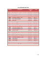
2.1: Example of International Ring Sizes Conversion Chart
3.1: List of Materials
4.1 : Trial Results in Standard Size
4.1.1: Equivalent Measurement in Diameter (mm) First Trial
4.1.2: Equivalent Measurement in Diameter (mm) Second Trial
4.1.3: Equivalent Measurement in Diameter (mm) Third Trial
4.3 Automatic Ring Sizer Test Results
20
42
52
53
54
55
57
viii
LIST OF FIGURES
Figure
Figure
Figure
Figure
Figure
Figure
Figure
Figure
Figure
Figure
Figure
Figure
Figure
Figure
Figure
Figure
Figure
1.1:
2.1:
2.2:
2.3:
2.4:
2.5:
2.6:
2.7:
2.8:
2.9:
3.1:
3.2:
3.3:
3.4:
3.5:
3.6:
3.7:
Conceptual Framework of the System
Finger Measurer
Example of the Sizers Produced in a School Design
Ring Sizer
Ring Stick
Finger Ring Size Adjusting Device
Finger Ring Size Adjusting Device in a Finger
In A Fiber-Optic Sensing System
Stepper Motor
Vernier Caliper
Design Procedure
Actual Design Procedure
Block Diagram of Hardware Design
Schematic Diagram of Hardware Design
Main System Flowchart
Customer Record Flowchart
Ring Selection & Ring Record Flowchart
3
16
16
17
17
21
22
23
24
25
29
30
36
37
46
47
48
ix
Chapter 1
DESIGN BACKGROUND AND INTRODUCTION
Design Setting
People from all cultures are fond of wearing jewelries for personal
adornment. One kind of jewelry is the ring which is a circular band usually used
to decorate the fingers.
Different techniques are used in measuring the size of the finger. During
ancient times measuring the size of the finger made use of a string, ruler, pen
and paper. The technique was to wrap a piece of string or strip of paper around
the finger, making sure that it was neither too tight to bind and that it could slide
over the knuckle of one‘s finger without difficulty, nor so loose that it would slip
over the knuckle almost by itself, thus easily fell off. Finding this comfort zone,
marked the point where the two ends meet. Lastly, lay the string or strip of
paper against a ruler to determine the circumference and record it.
Today, jewelry shops used improvise ring sizer or ring stick to measure
the finger size. The ring sizers are marked with different ring sizes and the
customer determines which one fits well.
1
Statement of the Problem
Today, to determine the finger size jewelry owners make use of different
manual measuring devices like using strings and rulers or improvised ring sizers
and ring sticks used by most jewelry shops. Ring sizers are circular bands that
have different diameter sizes. Many customers had found that trying on wedding
bands in different diameter sizes was the easiest way to determine the exact ring
size, but the method was tedious and would consume much time. Given this
premise, the proponents desired to improve the manual operation in determining
the finger size and choosing the clients preferred rings without hassle.
The Objective of the Design
The primary objective of this design is to automate the existing manual
technique in measuring the sizes of the fingers. Listed below are few things that
the proponents want to attain on the design to make it more efficient like:
1. To be able to utilize a sensor that will measure the size of the finger.
2. To create a database that will store the customer‘s profile and finger
sizes which can be used for future references.
3. To interface the design to the computer with the use of serial
communication.
2
The Significance of the Design
The design will be beneficial to the jewelry shop owners, sales staffs, and
customers. With the Automatic Ring Sizer and Availability Checker, the customers
will be given easier and convenient way to measure their finger sizes. This may
increase customer service satisfaction; hence the sales staffs could accommodate
more customers and increase the profits of the jewelry shop owners at the
shortest time compared to the manual process.
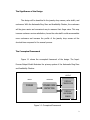
The Conceptual Framework
Figure 1.1 shows the conceptual framework of the design. The InputProcess-Output Model illustrates the primary system of the Automatic Ring Sizer
and Availability Checker.
OUTPUT
INPUT
PROCESS
FINGER
FINGER SIZE
DETECTOR
DISPLAY
FINGER SIZE
DISPLAY
AVAILABLE
RINGS
Figure 1.1: Conceptual Framework
3
Automatic ring sizer and availability checker is an automatic device used
to determine the size of the finger of the customer. The design will begin its
operation when the finger is positioned to the ring sizer hardware properly. The
finger serves as the input data of the device. The prototype is serially interfaced
to a computer terminal using a DB-9 Connector. The design uses a
microcontroller which controls the movement of the Unipolar Stepper Motor. The
stepper motor determines the size of the finger by counting the number of
rotation it has made. The stepper motor stops when the fiber optic proximity
sensor reflected beam is interrupted by an opaque object. The enter button on
the computer is pressed to complete the process. Since the fiber optic proximity
sensor is a non-contact sensor, offset value is added to the original size. The
output data, finger size is directly send to the customer‘s database and stored.
Upon storing the size of the customer‘s finger, the customer can choose different
rings from the database. It has a database for different ring images and sizes
and customer‘s profile.
The Scope and Delimitation
The proponents have set the scope and delimitation of the design as
follows:
Scope:
1. The prototype performs an operation that automatically measures the
size of the finger.
4
2. The prototype can measure one finger at a time.
3. The prototype makes use of stepper motor and fiber optic proximity
sensor. The stepper motor stops when an object interrupted the
reflected beam of the fiber optic proximity sensor.
4. The prototype utilizes serial port communication using DB-9 connector
cable that can be used on desktop computer.
5. The prototype adds a constant offset value to the original measure of
the finger because the fiber optic proximity sensor used is a noncontact sensor.
6. The design software can add, modify, and delete information of the
customer.
7. The design software can modify and delete existing ring record.
8. The design measurement ranges from 10mm (minimum) to 25mm
(maximum).
9. The final measure of the finger which is in millimeter is converted to
the USA Standard Ring Size using the International Ring Size
Conversion Chart.
Delimitation:
1. The fiber optic proximity sensor used is a non-contact type of sensor.
2. The prototype measures the diameter of the finger.
3. There is no level of hierarchy for account logging.
5
4. The program does not utilize a module for adding entry for new ring
information.
5. The design software does not generate sale transactions.
6. Fingers should not be measured when the temperature is cold; this is
when fingers are their smallest.
Definition of Terms
1. Alternating Current. Electric current that reverses direction periodically,
usually many times per second. (Beaty H., Standard Handbook for
Electrical Engineers, 15th Edition, 2007).
2. Capacitor. A device which consists essentially of two conductors (such as
parallel metal plates) insulated from each other by a dielectric and which
introduces capacitance into a circuit, stores electrical energy, blocks the
flow of direct current, and permits the flow of alternating current to a
degree dependent on the capacitor‘s capacitance and the current
frequency. (Terrell Croft, American Electricians‘ Handbook, 15th Edition,
1992).
3. Compiler. An application program in development software packages
that controls the design flow process and translates source code into
object code in a format that can be logically tested or downloaded to a
6
target device. (Floyd, L. T., Digital Fundamentals with PLD Programming.
New Jersey: Pearson Prentice Hall, 2006).
4. Database. A collection of information organized in such a way that a
computer program can quickly select desired pieces of data. One can think
of a database as an electronic filing system. (Takahashi, The Manga Guide
to Databases, 2006).
5. DB 9 Connector. A serial port connector which includes nine important
signal pin connectors. (Thompson et al., PC Hardware in a Nutshell, 3rd
edition, 2003).
6. Debugging. Error made in writing a program by which error the users
are not aware. Errors can be quite simple such as typing errors and quite
complex such as incorrect use of program language. Assembler will find
most of these errors and report them to '.LST' file. Other errors will need
to be searched for by trying it out and watching how device
functions. (Nebojsa Matic, PIC microcontrollers, 2005).
7. Diode. It consists of a silicon wafer containing nearly equal p-type and ntype impurities, with additional p-type impurities diffused from one side
and additional n-type impurities from the other side. This leaves a lightly
doped intrinsic layer in the middle to act as a dielectric barrier between
the n-type and p-type regions which is also known as power diode.
(Christiansen, Standard Handbook of Electronic Engineering, 5th Edition,
2005).
7
8. Etching. It is the process of using strong acid or mordant to cut into the
unprotected parts of a metal surface to create a design in intaglio in the
metal. (Abrams, et al., Computer Hardware and Software, Illustrated
Edition, Addison-Wesley, 1973).
9. Fiber Optic Proximity Sensor. A proximity sensor is a device used to
detect the presence of an object. Fiber optic proximity sensors are devices
which use a light beam transmitted from a light source by way of a bundle
of light conducting optical fibers from a light source to a target. (Brian S.
Elliott, Electromechanical Devices and Components Illustrated Sourcebook,
2007).
10. Finger. It is a digit of the hand, including the thumb. (Hanson,
Contemporary Ergonomics, 2001).
11. Graphical User Interface (GUI). A method of interacting with the
computer that allows any image to be displayed on screen (graphics
based). Although a keyboard is used to enter text, the primary way to
command the computer is with a mouse or touchpad pointing device.
(Takahashi, The Manga Guide to Databases, 2006).
12. Hardware. Machinery and equipment (CPUs, disk and tape drives,
modems, keyboards, printers, scanners, cables, etc.). In operation, a
computer is both hardware and software. One is useless without the
other. The hardware design specifies the commands it can follow, and the
8
software instructions tell what to do. (Takahashi, The Manga Guide to
Databases, 2006).
13. HEX File. This is a file made by assembler translator when transcoding
a source file and has a form "understood" by microcontrollers. A
continuation of the file is usually File_name.HEX where the name HEX
file comes from. (Nebojsa Matic, PIC microcontrollers, 2005).
14. Input/Output Pin. External microcontroller's connector pin which can
be configured as input or output. In most cases I/O pin enables a
microcontroller to communicate, control or read information. (Nebojsa
Matic, PIC microcontrollers, 2005).
15. Knuckle. The rounded prominence formed by the ends of the two
adjacent bones at a joint —used especially of those at the joints of the
fingers. (Hanson, Contemporary Ergonomics, 2001).
16. Metal Oxide Semiconductor Field-Effect Transistor. A field-effect
transistor having a gate that is insulated from the semiconductor
substrate by a thin layer of silicon dioxide. Abbreviated MOSFET; MOST;
MOS transistor formerly known as insulated-gate field-effect transistor
(IGFET). (Harper, Electronic Materials and Processes Handbook, 3rd
Edition, 2006).
17. Microcontroller. A microcomputer, microprocessor, or other equipment
used for precise process control in data handling, communication, and
9
manufacturing. (Donald Christiansen, Standard Handbook of Electronic
Engineering, 5th Edition, 2005).
18. Offset. The distance from a starting point, either the start of a file or
the start of a memory address. Its value is added to a base value to
derive the actual value. (Hanson, Contemporary Ergonomics, 2001).
19. PIC16F84A Microcontroller.
It
belongs
to
a
class
of
8-bit
microcontrollers of Reduced Instruction Set Computers architecture.
(Nebojsa Matic, PIC microcontrollers, 2005).
20. Plug. The half o f a connector that is movable and is generally attached
to a cable or removable sub-assembly inserted in a jack, outlet,
receptacle, or socket. (Terrell Croft, American Electricians' Handbook,
15th Edition, 1992).
21. Power Switch. An electric switch which energizes or de-energizes an
electric load, ranges from ordinary wall switches to load-break switches,
and disconnecting switches in power systems operating at voltages of
hundreds of thousands of volts. (Basso, Switch-Mode Power Supplies:
SPICE Simulations and Practical Designs, 2008).
22. Printed Circuit Board. A flat board whose front contains slots for
integrated circuit chips and connections for a variety of electronic
components, and whose back is printed with electrically conductive
pathways between the components. It is also known as circuit
board. (Coombs, Printed Circuits Handbook, 5th Edition, 2001).
10
23. Program. A collection of instructions that tells the computer what to do.
A program is generically known as "software" and the programs‘ users
work with such as word processors and spreadsheets are called
"applications" or "application programs." Thus, the terms software,
application, program, and instruction are synonymous in the sense that
these all tell the computer what to do. (Takahashi, The Manga Guide to
Databases, 2006).
24. Proximity Sensor. Any device that measures short distances within a
robotic system and also known as noncontact sensor. (Elliott,
Electromechanical Devices and Components Illustrated Sourcebook,
2007).
25. Resistor. A device designed to have a definite amount of resistance
used in circuits to limit current flow or to provide a voltage drop.
(Christiansen, Standard Handbook of Electronic Engineering, 5th Edition,
2005).
26. Ring. A band usually made of precious metal and often engraved or
mounted with gemstones worn as an ornament especially around a
finger. (Hanson, Contemporary Ergonomics, 2001).
27. Ring Sizer. A measuring device for the fingers which is a circular band
with different sizes. (Celis, Personal Interview, 2009).
11
28. Ring Stick. A measuring device for the fingers which is a cylindrical
cone that has markings on the edge denoting the size of the ring. (Celis,
Personal Interview, 2009).
29. RS-232 (Recommended Standard-232). A TIA/EIA standard for
serial transmission between computers and peripheral devices (modem,
mouse, etc.) Using a 25-pin DB-25 or 9-pin DB-9 connector, its normal
cable limitation of 50 feet can be extended to several hundred feet with
high-quality cable. (Elliott, Electromechanical Devices and Components
Illustrated Sourcebook, 2007).
30. Serial Interface. A data channel that transfers digital data in a serial
fashion: one bit after the other over one wire or fiber. The serial port on
a PC is a serial interface that is typically used to attach modems and
data acquisition terminals. On earlier PCs, mice are also used as the
serial port. USB and FireWire (IEEE 1394) are high-speed serial
interfaces that have superseded the serial port. Serial interfaces may
have multiple lines, but only one line is used for data. (Elliott,
Electromechanical Devices and Components Illustrated Sourcebook,
2007).
31. Simulator. Software package for PC which simulates the internal
function of microcontroller. It is ideal for checking software routines and
all the parts of the code which does not have over demanding
connections with an outside world. Options are installed to watch the
12
code, movement around the program back and forth, step by step, and
debugging. (Nebojsa Matic, PIC microcontrollers, 2005).
32. Software. This deals with the details of an ever-changing business and
must process transactions in a logical fashion. Languages are used to
program the software. The "logic and language" involved in analysis and
programming is generally far more complicated than specifying a
storage and transmission requirement. (Takahashi, The Manga Guide to
Databases, 2006).
33. Stepper Motor. A motor that rotates in short and essentially uniform
angular movements rather than continuously, typical steps are 30, 45,
and 90°; the angular steps are obtained electromagnetically rather than
by the ratchet and pawl mechanisms of stepping relays. (Elliott,
Electromechanical Devices and Components Illustrated Sourcebook,
2007).
34. Switch Mode Power Supply. It is an electronic power supply unit that
incorporates a switching regulator. The AC mains insert a 120-VRMS AC
signal into the SMPS input, where high amplitude transients attempting
to enter the supply and cause damage will be shortened to ground
through MOV (metal oxide varistor), thus imparting limited protection
from any voltage surges or lightning strikes. (Sayre, Complete Wireless
Design, 2nd Edition, 2008).
13
35. TTL (Transistor-Transistor Logic). A type of fixed-function digital
circuit technology that uses bipolar junction transistors. (Floyd, Digital
Fundamentals with PLD Programming. New Jersey: Pearson Prentice
Hall, 2006).
36. Universal Asynchronous Receiver Transmitter (UART). The
electronic circuit that makes up the serial port. Also known as "universal
serial asynchronous receiver transmitter" (USART), it converts parallel
bytes from the CPU into serial bits for transmission and vice-versa. It
generates and strips the start and stop bits appended to each character.
Note that in the following paragraphs, dashes have been added after the
16 for readability. Older 8250 and 16-450 UARTs are not fast enough for
today's modems. A 16-550 is required for transmission up to 115,200
bps (115 Kbps). (Elliott, Electromechanical Devices and Components
Illustrated Sourcebook, 2007).
37. Vernier Caliper. An instrument used for in determining accurate linear
measurements.
(Elliott, Electromechanical Devices and Components
Illustrated Sourcebook, 2007).
38. Voltage Regulator. A device that maintains the terminal voltage of a
generator or other voltage source within required limits despite
variations in input voltage or load. (Beaty, Standard Handbook for
Electrical Engineers, 15th Edition, 2007).
14
Chapter 2
REVIEW OF RELATED LITERATURE AND RELATED STUDIES
The concept of the design comes from existing ideas and related studies
that are done in the past. The design prototype is unique and one of a kind
because the resources used happened to be limited. Books, magazines, internet,
and interviews from jewelry shop sales staff became the primary source of
information regarding different methods in measuring finger sizes. It provides
knowledge on how to measure ring sizes manually.
Different Manual Methods/Devices Used in Measuring Ring Size
According to the concepts from the book, The Budget Wedding
Sourcebook by Madeline Barillo it stated that choosing wedding and engagement
rings were a momentous decision not only on the style of the ring but also in
terms of its sizes. The ring should fit properly and comfortably over the knuckle
and hug the base of the finger without sliding around too easily. So, when
buying a ring it is important to have the right size. A person would not want to
have a ring that didn‘t fit properly. It will be very disappointing if a ring was too
big or too small that is why measuring ring size is important in buying any type
of ring.
15
Hence, the proponents have decided
to create an automatic ring sizer
and availability checker which is an alternative way of measuring the size of the
fingers in automatic mode. These concepts were used as significant information
implementing the design prototype since it involved measuring ring sizes.
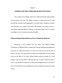
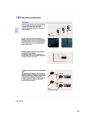
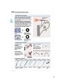
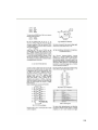
Figure 2.1: Finger Measurer
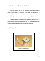
Figure 2.2: Example Of The Sizers
Produced In A School Design
An article taken from the magazine Applied science entitled ―Science
Applied to Wedding Rings‖ by Julius Dinhofer of New York (2005) invented a
finger measurer shown in Figure 2.1. This device is a strip of paper film with a
slit in one end through which the other end may pass. It is designed to measure
the size of the finger by slipping the end of the paper through the opening and
adjusting it to the finger. And it has a scale printed along on the edge of the
paper which tells the size of the finger.
Another technique in measuring the size of the finger is to use a ring sizer
as shown on Figure 2.2. According to a book, Contemporary Ergonomics, by
16
Margaret Hanson, 2001, Ergonomics Society Conference, a ring sizer is a
measuring device for fingers which is composed of circular bands that have
different sizes. The designer recorded the smallest size through which the finger
would freely pass without the application of force.
The proponents studied Hanson‘s work. It measured the diameter of the
finger. Also, the movements of the unipolar stepper motor corresponded to a
single step. For every one revolution of the motor created was equivalent to 1
millimeter in size. The generated steps to complete one cycle of the motor were
200 steps having 1.8º movements.
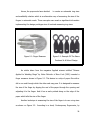
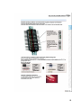
Figure 2.3: Ring Sizer
Figure 2.4: Ring Stick
17
From the team‘s interview with Ms. Jhonasel R. Celis, Sales Staff of Suarez
Wedding Rings Shop, where the shop used two kinds of measuring devices,
namely: a ring sizer and a ring stick. Figures 2.3 and 2.4 are examples of ring
sizers and ring stick that are presently used in most jewelry shops and designed
for measuring ring sizes. Celis discussed on how to measure the size of the
fingers using the said devices. First, the ring stick (graduated cone) was used
when an available ring was present. Ring stick had markings on the cone
denoting the ring sizes. The ring was put on the cone and its size was read
where it fitted securely on the cone. Otherwise, the ring sizers were used. Ring
sizers were usually group of rings with different sizes. As shown in Figure 2.3,
there were two kinds of ring sizer. A ring sizer that was 1mm thick for standard
rings and a ring sizer that was 3mm thick for engagement/wedding ring.
The discussed procedures were used by the proponents in comparing the
results of the automatic ring sizer from the manual process to determine the
measurement of the finger. The standard ring size and ring stick that was
purchased in the market was used.
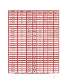
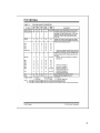
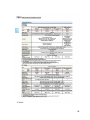
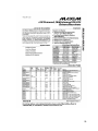
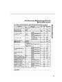
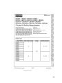
Table 2.1 is an excerpt from the International Ring Size Conversion Chart.
Different countries have different ring-size systems. The American Standard
Measurement is the common ring standard used in measuring the size of the
finger. It shows the inside circumference or diameter (in inches and millimeter)
size of the ring and the corresponding ring sizes by other countries.
18
The table was used for the Ring Calibration and Finger Diameter
Measurement System 1.0. The obtained measurement of the design prototype
(in millimeter) was converted using the USA size of the International Ring Size
Conversion Chart.
19
Inside
Circumference
(inches)
1 12/16
Inside
Circumference
(mm)
46
Inside
Diameter
(mm)
14.68
1 14/16
46
1 13/16
U.S.A.
size
Japanese
size
3¾
5
G½
14
6 1/2
14.88
4
6
H
14 ½
--
47
15.09
4¼
7
H½
15
7 3/4
1 14/16
48
15.27
4½
8
I-½
15 1/4
--
1 15/16
49
15.70
5
9
J½
15 3/4
--
2
51
16.10
5½
11
L
16
11 3/4
2 1/16
52
16.51
6
12
M
16 1/2
12 3/4
2 2/16
53
16.92
6½
13
N
17
14
2 3/16
55
17.35
7
14
O
17 1/4
15 1/4
2 4/16
56
17.75
7½
15
P
17 3/4
16 1/2
2 5/16
57
18.19
8
16
Q
18
17 3/4
2 6/16
58
18.53
8½
17
Q½
18 1/2
--
2 7/16
59
18.89
9
18
R½
19
--
2 8/16
61
19.41
9½
19
S½
19 1/2
--
2 9/16
62
19.84
10
20
T½
20
--
2 10/16
63
20.20
10 ½
22
U½
20 1/4
--
2 11/16
65
20.68
11
23
V½
20 3/4
--
2 12/16
66
21.08
11 ½
24
W½
21
--
2 13/16
68
21.49
12
25
Y
21 1/4
27 1/2
2 14/16
69
21.89
12 ½
26
Z
21 3/4
28 3/4
2 15/16
70
22.33
13
27
--
22
--
3
71
22.61
13 ½
--
--
--
--
3 1/16
72
23.01
14
--
Z3
--
--
3 2/16
73
23.42
14 ½
--
Z4
--
--
3 3/16
74
23.83
15
--
--
--
--
3 4/16
76
24.23
15 ½
--
--
--
--
77
24.64
16
---Table 2.1: Example Of International Ring Sizes Conversion Chart
--
3 5/16
British German
size
size
Swiss
size
20
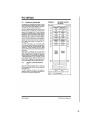
Finger Ring Size Adjusting Device and Method
An article entitled ―Finger Ring Size Adjusting Device and Method‖ by
Bryan J. Miller, the inventor from United States Patent Online, Patent Number
6003334 2005, stated that the invention relates generally to a finger ring size
opening adjustment device for enhancing the retention of a finger ring on the
wearer‘s finger and, more particularly to an adjustment device adapted to the
ring shaft in permitting passage of the ring over an enlarged knuckle for fitting a
digital portion of the finger.
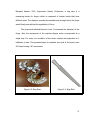
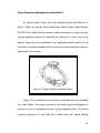
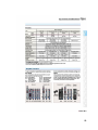
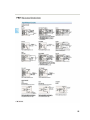
Figure 2.5: Finger Ring Size Adjusting Device
Figure 2.5 is an example of the invention in elevation view, an adjustable
ring sizing device. The topics discussed in the article gave the designers an
overview on how to automate the finger ring size adjusting device. The device
invented comprised of a ring shaft and a cradle which was biased radically
21
inward from the shaft. The cradle was moveable between a retracted position
and an adjusted position for reducing the ring size. The ring wearer, thus had an
adjustable ring shaft for easily sliding over an enlarged knuckle or joint, and then
to a desired fit on the phalanx portion of the finger.
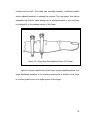
Figure 2.6: Finger Ring Size Adjusting Device In A Finger
Fgure 2.6 shows a partial view of the finger ring size adjusting device on a
finger illustrating operation of the invention passing over a knuckle of the finger
to a closed position worn on a digital portion of the finger.
22
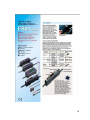
Fiber Optic Proximity Sensor
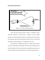
Figure 2.7: In A Fiber-Optic Sensing System
A fiber optic sensor system as shown in Figure 2.7 consisted of a fiberoptic cable connected to a remote sensor, or amplifier. The sensor emitted,
received, and converted the light energy into an electrical signal. The cable was
the mechanical component that transported the light into and out of areas that
were either too space constrained or too hostile back to the sensor.
The measurement of displacement, position, or location was an important
concept in the development of this design. Thus, fiber optic proximity sensor was
used. Some features of fiber optic proximity sensor provided high precision up to
0.002mm resolution and high temperature up to 170º Celsius operating range.
23
Foot Size Measurer and Foot Size Availability Checker
Foot Size Measurer and Foot Size Availability Checker was a previous
design by Delos Santos et al., July 2006. In this design the materials used in
measuring the size of the foot consisted of a microcontroller, stepper motor, and
two switches. It was interfaced to the computer using a parallel cable.
The design gave the proponents to come up with the concepts on how to
develop another design which measured the size of a finger automatically and
showed the available desired ring with the customer‘s finger size.
Unipolar Stepper Motor
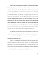
Figure 2.8: Stepper Motor
24
From the Standard Handbook for Electrical Engineers, 15th edition Beaty
2007, stated it that the primary characteristic of a stepper motor was its ability to
rotate a prescribed small angle (step) in response to each control pulse applied
to its windings. About 200 pulses per second, the motor rotated in discrete steps
in synchrony with the pulses at higher frequencies up to 16,000 pulses per
second, the motor skewed without stopping between pulses. Although motors
were available for step angles of 90º to 180º, the common step was 1.8º.
Unipolar Stepper Motor as shown in Figure 2.8 was applied in the design
because it required controlled movement. It can be used as an advantage in
applications where it needed speed, position and synchronization. Since the
design needed speed and controlled movement in measuring the size of the
finger the stepper motor was used.
Vernier Caliper
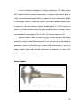
Figure 2.9: Vernier Caliper
25
As stated in the Brittanica‘s Encyclopedia, vernier caliper Figure 2.9 is an
instrument used for in determining accurate linear measurements. As shown, it
utilized two graduated scales: a main scale similar to that of a ruler and
especially graduated auxiliary scale. The vernier that slides parallel to the main
scale and enables readings to be made to a fraction of a division on the main
scale. Vernier calipers are widely used in scientific laboratories and in
manufacturing for quality control measurements.
The proponents have conceptualized the design into a form of this caliper.
Some sort of instrument to help detect the displacements of an object. Inasmuch
as it is a caliper, the idea of displacement being used for the measurement of the
design came from the vernier concept.
Effect of Temperature in Finger Muscles
As stated in Encyclopaedia of Occupational Health and Safety by Jeanne
Mager Stellman, International, 2001; ―There is a pronounced effect of cold on
muscular functions and performance.‖ Coolness of the environment contract
muscles and slows down neural processes.
With this in mind, problems may arise in the precision measuring of the
device in cold temperature. Measurements may vary when taken from different
room temperature but the differences are in fractions of a millimeter.
26
Chapter 3
DESIGN METHODOLOGY AND PROCEDURES
Design Methodology
Developmental research was used as the design methodology of this
research. It is defined as a systematic study of designing, developing and
evaluating constructional programs, processes, and products that must meet the
criteria of internal consistency and effectiveness (Design & Development
Research, Richey & Klein, 2001). It is a process to examine the usefulness and
accurateness of automatic ring sizer as to the traditional manual method in
determining the size of the finger. To further understand the design concepts,
additional information and concepts needed were gathered from books,
magazines, and interviews from the jewelry shop salesclerks became the primary
source of information regarding different methods in measuring finger sizes. The
gathered data provided knowledge on how to automate and implement the
design prototype.
27
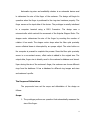
Design Procedure
Figure 3.1 shows the flowchart diagram on how the research study was
done. The first step was to identify the problem which was how to automate the
existing manual process in determining the ring sizes. The next step after
identifying the problem is to form possible solutions that could help in the
development of the design. Then, relevant and informative data were gathered
to support the research study, such as related literature and studies. These
related literature and studies are basically organized and synthesized collection
of citations taken from other articles and studies. Then followed by collecting
information concerning the materials and components to be used which are
appropriate and suitable for the design prototype. The development of the
design started when all the required materials and components were available.
28
Start
Define the problem:
How to automate the existing manual
ring sizers?
Form possible solutions to the problem
Gather related literature and studies
Is the data
informative?
N
Y
Gather information for the materials and
components appropriate for the design
prototype
Is it suitable for
the design?
N
Y
Develop the design prototype
Test the design prototype
End
Figure 3.1: Design Procedure
29
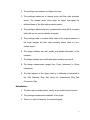
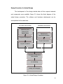
Design Procedure for Actual Design
The development of the design started when all the required materials
and components were available. Figure 3.2 shows the block diagram of the
actual design procedure. The software and hardware development can be
accomplished at the same time.
SOFTWARE DEVELOPMENT
HARDWARE DEVELOPMENT
Establishing and
Analyzing the
Requirements
Materials and
Components Available
Program Development
Circuit Construction
Program Simulation
Integration of Hardware
and Software
PC Interfacing
Testing and Debugging
Figure 3.2: Actual Design Procedure
30
The step by step procedures that the proponents followed in constructing
the research design are as follows:
SOFTWARE DEVELOPMENT
1. Establishing and analyzing the requirements
a. The work began by establishing the requirements needed in the
software. This was the most important task in creating software.
The proponents discussed all the applicable factors and concepts in
development of the software program.
b. Once the ideal system was engineered or brought about, the
proponents analyzed the software requirements for the system.
Some functionality may be out of scope on the design functions as
cost or as a result of unclear requirements at the start of
development. Hence, the overall software‘s requirements and
structures should be clearly stated.
2. Program Development
a. The design must be translated into a machine-readable form. The
procedure that executed this task was the code generation.
b. Create the program, successfully compile it and then generate the
HEX file.
c. MPASM v03.30-Microchip application was used to generate the HEX
file of the program made.
31
d. The programming tool MicroC Electronica was used for coding and
was developed using the C Language. The generated program will
be shown in the latter part of this chapter.
e. Then, burn the program using a compatible Microchip PIC kit
burner.
3. Program Simulation
a. Using the MicroC Electronica simulated the code generated and
checked if all functions were working properly and if there were no
errors.
HARDWARE DEVELOPMENT
1. Materials and components available.
a. The design started after gathering all the material components and
information needed for the creation of the design prototype.
2. Circuit Construction.
a. Using the PCB Wizard software, develop the PCB layout of the
automatic ring sizer. Print the PCB layout in acetate.
b. Cut the printed circuit board.
c. Position the printed acetate with PCB layout on top of the printed
circuit board. Expose it to UV light for about 30 seconds up to 1
minute.
32
d. Dissolve right amount of developer in water. Place the exposed
printed circuit board into the solution and wait until the solution
reacts with the PCB. Notice that the printed circuit board changes
color.
e. Etch the layout on the printed circuit board.
f. When the layout is clear and visible, wash the PCB with water.
Place the etched circuit board on a ferric chloride solution to
dissolve unwanted copper by shaking the container. Wash the
board with water and put to dry when all unwanted copper is
removed.
g. Test all the connections of the circuit board using the VOM. Check
for continuity.
h. Drill holes on the board according to the proper layout of the
components.
i. Assemble all the components needed for the design except for the
microcontroller.
j. Solder all the components on the board properly.
INTEGRATION OF HARDWARE AND SOFTWARE
1. Using a PIC16F84A device programmer, upload the HEX file into the
PIC16F84A. The step is often called ―burning‖.
33
2. Put into position the microcontroller on the corresponding IC socket on
the circuit board.
3. Place and screw the circuit board inside the casing.
4. Measure the dimensions of the switch, push buttons, DB-9 connector slot
for power supply cable hole. Outline the measurement on the plastic
casing and cut the edges on the marked outline. Mount the components
properly and screw it on.
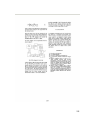
5. Construct a frame case for the fiber-optic proximity sensor head and
amplifier. Place the stepper motor on top of the frame case. The stepper
motor is connected to a movable rod which will serve as the point of
reference.
6. Measure and cut two 3 1/2-inch-long pieces of plastic to make arches. For
each arch, use a compass to draw a 1-inch-radius semicircle at the center
of one long edge, to form a 1-inch-high arch on one long side. Then
carefully cut the arch.
7. Make sure to mount properly the fiber-optic proximity sensor heads and
amplifiers.
8. Screw securely one arch in the movable rod and the other half at the
bottom of the frame. The finger is placed in this setup for measurement.
9. Connect all the ports from the circuit board to the stepper motor and
amplifier.
34
PC INTERFACING
1. Establish and analyze the software requirements for the database
software.
2. Generate a program code that could store customer‘s information and
sizes of fingers.
3. Using UART (Universal Asynchronous Receiver/Transmitter) establish a
code that involves connecting the design prototype to the computer
serially.
TESTING AND DEBUGGING
1. This phase demonstrates if the design is working according to its functions
and objectives.
2. Verify the program if it works as expected. Troubleshoot, if necessary.
35
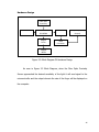
Hardware Design
Fiber-Optic
Proximity
Sensor
Switch Button
Microcontroller
PIC16F84A
Stepper
Driver
MAX 232
Computer (Display
Output)
DB-9
Connector
Stepper
Motor
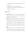
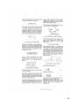
Figure 3.3: Block Diagram Of Hardware Design
As seen in Figure 3.3 Block Diagram, when the Fiber Optic Proximity
Sensor approached the desired sensitivity of the light it will send signal to the
microcontroller and the output wherein the size of the finger will be displayed on
the computer.
36
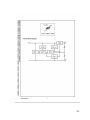
Circuit Design
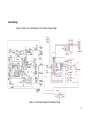
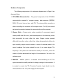
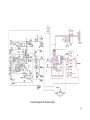
Figure 3.4 shows the circuit diagram of the whole prototype design.
Figure 3.4: Schematic Diagram Of Hardware Design
37
Hardware Components
The following components in the schematic diagram seen in Figure 9 are
discussed below:
1. PIC16F84A Microcontroller – The general components of the PIC16F84A
microcontroller consisted of program memory, data memories (EEPROM,
RAM), I/O ports, free-run timer and CPU. The microcontroller served as a
device controlling the movement of the stepper motor. The I/O ports served
as physical connections between the microcontroller and the computer.
2. Stepper Motor – Stepper motor system consisted of a permanent magnet
rotating shaft called the rotor, and electromagnets on the stationary portion
that surrounded the motor called the stator. Stepper motors operated
differently from other motors; rather than voltage being applied and the rotor
spun smoothly, stepper motors turned on a series of electrical pulses to the
motor's windings. Each pulse rotated the rotor by an exact degree. The
frequency of the pulse train controlled the velocity of the motor, where the
number of pulses determined the length of the movement of the rod to the
reference point.
3. MAX232 – MAX232 system is a standard serial interfacing for PC. The
system was used to serially interface the design prototype to the computer. It
is needed to convert the TTL (Transistor-Transistor Logic) levels from the
microcontroller to the 12 V power supply for the computer.
38
4. Fiber-Optic Proximity Sensor (Head/Amplifier) - Fiber optic proximity
sensors used to detect the proximity of target objects. For position
measurement sensors, this was the distance range over which the position
vs. output response which was linear and stable. The minimum detectable
object was the smallest sized object detectable by the sensor. The response
time was the time from target object entering detection zone to the
production of the detection signal.
5. Switch Mode Power Supply – It incorporated power handling electronic
components which were continuously switched on and off with high
frequency. It effectively connects and disconnects energy storing inductors to
and from the input source.
6. DB9 Connector - The DB9 connector is mainly used for serial connections,
allowing for the asynchronous transmission of data as provided for by
standard RS-232 (RS-232C).
7. DB9 Serial Data Cable – This is used to provide direct data transfer from a
control device to a display device.
8. Diode 1N4006 - A diode is placed after the stepper motor to avoid feedback
effect of the electric charge.
9. MOSFET 03N06 – It is a device used to amplify or switch electronic signals.
10. Resistor – It is used to determine the flow of current where there is high
resistance in a circuit the flow of current is small and when the resistance is
low the flow of current is large.
39
11. Capacitor – It is a device used for storage of electric charge.
12. Transformer – A device that transfers electrical energy from one circuit
to another through inductively coupled electrical conductors
13. Voltage
Regulator
7805
-
An
electrical
regulator
designed
to
automatically maintain a constant voltage level.
14. Power Switch - An electric switch which energizes or de-energizes an
electric load; ranges from ordinary wall switches to load-break switches and
disconnecting switches in power systems operating at voltages of hundreds of
thousands of volts.
15. Plug - A male fitting for making an electrical connection to a live circuit by
insertion in a receptacle.
16. AC Cord – It is a cable that temporarily connects an electrical appliance to
the distribution circuits of an electrical power source via a wall socket or
extension cord.
40
List of Materials
Quantity
Description
2 pcs
Fiber Optic Proximity Sensor Head
2 pcs
Fiber Optic Proximity Sensor Amplifier
1 pc
Unipolar Stepper Motor
1 pc
Max232 IC
3 pcs
Capacitor 0.1µF
1 pc
DB-9 Cable Connector
1 pc
DB-9 Port
1 pc
PIC16F84A Microcontroller
6 pcs
Resistors 22KΩ
4 pcs
Resistors 400Ω
1 pc
Crystal Oscillator 4MHz
2 pcs
Capacitor 33pF
1 pc
Capacitor 0.1µF
4 pcs
MOSFET03N06
4 pcs
Diode 1N4006
1 pc
Switching Mode Power Supply
1 pc
7805 Voltage Regulator
1 pc
Capacitor 4700µF
1 pc
Capacitor 1000µF
2 pcs
Push Buttons
1 pc
Power Switch
1 pc
Power Plug
1 pc
Casing
Table 3.1: List of Materials
The list of components that the proponents have used in creating the
design is shown on table 3.1.
41
Hardware Implementation
The proponents designed the prototype upon completing the research
study. They thoroughly selected the components and materials needed to
implement the design prototype. The design prototype was tested to different
individuals. They compared the results of the automatic ring sizer to the manual
ring sizer to show the accuracy of measurement of the prototype.
Software Design
The program for the microcontroller was meant for measuring the finger.
The program was created using the MicroC Electronica Compiler that works in C
language. The microcontroller controls the movement of the stepper motor,
counts the number of revolution made by the stepper motor and displays the
generated output to the computer using serial connection. With the MAX232 the
system was used to serially interface the design prototype to the computer.
The program for the availability checker database was meant for the
client‘s profile, finger measurements, and ring database. The program was
created using Visual Basic 6.0 and Microsoft Access.
Software Component
Basically, the C Language and MicroC Electronica were used for
programming the microcontroller and Visual Basic 6.0 for the availability checker
database system. After programming, the code for the microcontroller was
42
compiled to the machine language and the machine code was burned to the
microcontroller. The team was able to generate, simulate and program the
software for the design with the appropriate features of the programming tool
used.
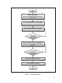
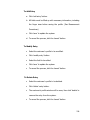
System Flowchart
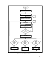
Figure 3.5 as shown on page 46 is the main system flowchart of the
design project. It illustrates how the operation of the system works. The basic
function of this design prototype is to measure the sizes of the fingers and to
show available rings.
The design prototype must be connected first to the computer using DB9
cable for safety measures. To start the system, press the power button to switch
of the device. Then, open the database application of the ring sizer and
availability checker. It will proceed to the main window of the database, the
administrator must log in first for security purposes. There are three options that
a user can choose from: to select customer ring, to manage customer record, or
to manage ring record.
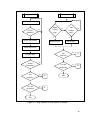
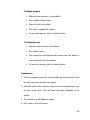
If the user chooses an operation to select customer ring, Figure 3.7 on
page 48 illustrates the ring selection flowchart. The user selects first the
customer‘s profile from the database. Then, the customer can decide which
finger he/she would like to buy a ring for. Once the customer has decided,
43
he/she can now choose from the available ring designs selection that fits to
his/her finger size. Afterwards, the customer can now purchase the ring item.
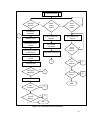
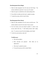
If the user chooses an operation to manage customer record, Figure 3.6
on page 47 illustrates the customer record flowchart. There are three options
that a user can choose from this operation: to add new record; to modify
existing record; or, delete existing record. To add a new customer record, the
information fields must be filled out first before measuring the finger. Then, the
user clicks the first finger variant to be measured. Afterwards, the device should
be reset by pressing the reset button on the prototype. Once the prototype is
reset, the customer can place the finger properly on the device and press enter.
The stepper motor will move and determine the number of revolution the
stepper motor made. The number of revolution of the stepper motor is
equivalent to the size of the finger in millimeters and is converted to the
international standard size of the ring. The stepper motor stops when the fiber
optic proximity sensor detects a finger. Since the fiber optic proximity sensor is a
non-contact sensor, an offset value is added to the original size. Eventually,
press the enter button on the device and the size of the finger is displayed on
the computer screen. All fingers must be measured for future references. Lastly,
save the new customer record. To edit an existing record, the user chooses a
customer profile to be modified. The user can edit the customer‘s information
and the finger sizes. Or, to delete an existing record, the user chooses a
customer profile to be deleted.
44
If the user chooses an operation to manage the ring record, Figure 3.7 on
page 48 illustrates the ring record flowchart. There are two options that a user
can choose from this operation: to delete existing ring record or to edit an
existing rings record. The user can delete existing ring record and indicate the
sizes of the available rings. Or, the user can modify an existing ring record.
The system will still continue working every after operation unless the
user chose to turn off the device by pressing the power off button.
45
START
Connect Device To Computer
Power On Device
B
Open Ring Measurer &
Availability Checker Database
A
Main Window
Login as user
N
Login
Correct?
Y
Main Menu
Select
Customer
Ring
Y
Ring Selection
N
Manage
Customer
Record
N
Y
Customer
Record
N
Manage
Ring
Record
Y
Ring Record
Figure 3.5: Main System Flowchart
46
Customer Record
Add New
Record?
1
N
Modify
Existing
Record?
Y
Fill Customer‘s
Information
N
Y
Delete
Existing
Record?
N
Y
Measure Finger
Choose Account to be
Modified
Press Reset on the
Device
Edit Customer
Information
Place Finger Properly
on the Device
Edit Customer Finger Size
Select Account to be
Deleted
Delete
Another
Account?
N
Y
Press Enter on the
Device
1
Display Output
Exit
Program
N
A
N
B
Y
All Fingers
Measured?
N
1
Save Record
Y
Turn Off
Device
Y
END
Exit
Program?
N
A
Y
Turn off
Device?
Y
N
B
END
Figure 3.6: Customer Record Flowchart
47
Ring Selection
Ring Record
Select Customer Name
Correct
Customer?
Delete
Existing
Ring?
N
Y
Edit
Existing
Ring?
N
Y
Select Finger Variant
N
Y
Edit an Entry
Delete an Entry
Select Ring Design
Exit
Program?
Purchase Ring
N
A
N
B
Y
Another
Transaction?
N
Turn Off
the Device?
Y
Exit
Program?
Y
N
A
N
B
END
Y
Turn Off
the Device?
Y
END
Figure 3.7: Ring Selection & Ring Record Flowchart
48
Chapter 4
TESTING, PRESENTATION, AND INTERPRETATION OF DATA
The design in this chapter was tested to further determine its functionality
and capability in handling the operation of the whole system.
This part is
important for the design for the proponents to determine and test whether the
design would work out well or not. On this part, they can have an idea on the
possible outcome of our design. Rigid testing was conducted to verify and check
if the expected sizes of finger in the output and the values gathered from the
tests would approximately be the same with the real size of a normal finger.
Outputs of the tests are shown in Table 4.1.
Expected Results
The expected finger sizes of an individual were shown on this part; the
values that the proponents expected from their test results were evidently the
same. They assumed that the normal person with normal physique would have
the same result compared to manual testing; results vary on how the person
would want the ring to fit in his finger.
The proponents conducted tests to determine the functionality of the
design and how precise it can measure. One of them performed to measure his
finger size using the design and advised to imagine that the ring will be a normal
fit; the proponents recommended this because they wanted to somehow get
49
closer to the exact results, and because results may vary on how fit the ring will
be on the finger. The design is an invention on how to measure the size of our
finger; this is because of the device the proponents used to trigger the output of
their design which is called fiber optic proximity sensor. Since this is a light
sensor device they came up with an offset value so that they would be able to
determine the accurate size where too many experiments were conducted. They
also conducted testing on other manual measuring devices like using the
different circular bands they bought beside‘s mercury drugstore in Quiapo. The
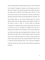
trial results are shown in Table 4.1. The first problem the researchers
encountered was to determine what the closest accurate offset value was? Due
to intensive trial and error experiment they conducted, they were able to
determine that the offset value of the design was 3.5 mm. Since the device used
was a fiber optic proximity sensor that triggered when the reflection of the light
was blocked by an object. Table 4.1 below showed the results of the experiment
using 3.5 mm as offset value. Based on the results, the value was almost the
same as of the manual ring sizer. The proponents conducted 3 Trials to be able
to verify that they have right offset value. On the 3 trials they conducted the
results they got was very close to each other, which showed how accurate was
the design.
50
Table 4.1: Trial Results in Standard Size
FINGER
MANUAL
AUTOMATIC
AUTOMATIC
AUTOMATIC
VARIANT
MEASUREMENT
RING SIZER
RING SIZER
RING SIZER
(Ring Sizer)
(Trial 1)
(Trial 2)
(Trial 3)
5.5
5.5
5.5
5.5
7.75
7.75
7.5
7.75
9.25
9.25
9
9
9.25
9.75
9.5
9.5
11
10.75
11.5
11.75
5.5
5.25
5.25
5.5
8.25
8
8
8
9.25
9
9.25
9.25
9.25
9.75
9.75
9.75
11
11.75
12
12
LEFT PINKIE
LEFT RING
LEFT MIDDLE
LEFT INDEX
LEFT THUMB
RIGHT PINKIE
RIGHT RING
RIGHT MIDDLE
RIGHT INDEX
RIGHT THUMB
Table 4.1 showed the results on the 3 trials obtained by converting the
results on Table 4.1.1, Table 4.1.2 and Table 4.1.3 by its diameter and the value
was in millimeters. It also showed the difference of the manual ring sizer to the
automatic ring sizer, and the difference was very minimal.
51
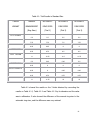
Table 4.1.1: Equivalent Measurement in Diameter (mm)
First Trial
FINGER
MANUAL
AUTOMATIC
VARIANT
MEASUREMENT
RING SIZER
(Ring Sizer)
(Trial 1)
16.1
16.1
0 mm
17.93
17.93
0 mm
19.15
19.15
0 mm
19.15
19.56
0.41 mm
20.57
20.37
0.2 mm
16.1
15.9
0.2 mm
18.34
18.14
0.2 mm
19.15
18.95
0.2 mm
19.15
19.56
0.4 mm
20.57
21.18
0.61 mm
DIFFERENCE
LEFT PINKIE
LEFT RING
LEFT MIDDLE
LEFT INDEX
LEFT THUMB
RIGHT PINKIE
RIGHT RING
RIGHT MIDDLE
RIGHT INDEX
RIGHT THUMB
52
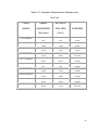
Table 4.1.2: Equivalent Measurement in Diameter (mm)
Second Trial
FINGER
MANUAL
AUTOMATIC
VARIANT
MEASUREMENT
RING SIZER
(Ring Sizer)
(Trial 2)
16.1
16.1
0
17.93
17.73
0.2
19.15
18.95
0.2
19.15
19.35
0.2
20.57
20.98
0.41
16.1
15.9
0.2
18.34
18.14
0.2
19.15
19.15
0
19.15
19.56
0.4
20.57
21.39
0.82
DIFFERENCE
LEFT PINKIE
LEFT RING
LEFT MIDDLE
LEFT INDEX
LEFT THUMB
RIGHT PINKIE
RIGHT RING
RIGHT MIDDLE
RIGHT INDEX
RIGHT THUMB
53
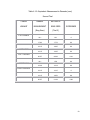
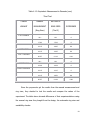
Table 4.1.3: Equivalent Measurement in Diameter (mm)
Third Trial
FINGER
MANUAL
AUTOMATIC
VARIANT
MEASUREMENT
RING SIZER
(Ring Sizer)
(Trial 2)
16.1
16.1
0
17.93
17.93
0
19.15
18.95
0.2
19.15
19.35
0.2
20.57
21.18
0.61
16.1
16.1
0
18.34
18.34
0
19.15
19.15
0
19.15
19.56
0.4
20.57
21.39
0.82
DIFFERENCE
LEFT PINKIE
LEFT RING
LEFT MIDDLE
LEFT INDEX
LEFT THUMB
RIGHT PINKIE
RIGHT RING
RIGHT MIDDLE
RIGHT INDEX
RIGHT THUMB
Since the proponents got the results from the manual measurement and
ring sizer, they decided to test the results and compare the values of the
experiment. The table above showed differences of their experimentations using
the manual ring sizer they bought from the design, the automatic ring sizer and
availability checker.
54
Difference Formula
Difference = Manual Measurement, mm.(Ring Sizer) – Automatic Ring Sizer, mm.
The outputs shown in the experimentation illustrated the accuracy of the
Automatic Ring Sizer and Availability Checker design prototype. Although the
proponents used an offset value, the design prototype invented was the best
design invented to measure a person‘s finger size. But in the end, the individual
will decide on how the ring will fit in his/her finger.
55
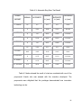
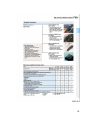
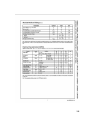
Table 4.3: Automatic Ring Sizer Test Result
FINGER
MANUAL
MANUAL
AUTOMATIC
VARIANT
L. PINKIE
L. RING
L. MIDDLE
L. INDEX
L. THUMB
R. PINKIE
R. RING
R. MIDDLE
R. INDEX
R. THUMB
DIFFERENCE
in (mm)
AUTOMATIC
in (mm)
in (mm)
5.5
5.5
16.1
16.1
0 mm
9
9.25
18.95
19.15
0.2 mm
11
11.5
20.57
20.98
0.41 mm
11
11.25
20.57
20.78
0.21 mm
11
11.5
20.57
20.98
0.41 mm
5.5
5.25
16.1
16.1
0 mm
9.25
9.25
19.15
19.15
0 mm
11
11.75
20.57
21.18
0.61 mm
11
11.75
20.57
21.18
0.61 mm
10.5
10.25
20.17
19.96
0.21 mm
Table 4.3 below showed the result of a test we conducted with one of the
proponents‘ friends who was amazed with the invention developed. The
proponents were delighted that the prototype demonstrated how innovation
technology can be.
56
Chapter 5
CONCLUSION AND RECOMMENDATION
Conclusion
By following the methodology of the design, a device that could
automatically and accurately measure the finger size was created. The
proponents concluded the following:
1. The use of fiber optic proximity sensor mounted on the design to
measure the exact size of a finger was effective since the test
results on Table 4.3 showed an efficient output.
2. The database created was useful in storing customer‘s profile and
finger sizes. This could be used not only in the existing market but
also for future references.
3. The device was successfully connected to the desktop by means of
the serial cable communication.
Recommendation
Some features that can be added or changed to the Automatic Ring Sizer
and Availability Checker are the following:
1. The appearance of the device should be changed so that fingers will
be comfortably placed while being measured.
57
2. A sensor that can accurately measure an object‘s circumference can be
used instead of the sensor that is used in the device.
3. The design can be improved in the future by measuring smaller finger
sizes than 15 mm finger diameter, and bigger finger sizes larger than
the 25 mm diameter size.
4. The device may also be improved by the use of parallel cable
communication or USB connection.
5. The device may also be developed by adding function which will
measure the circumference of the finger, rather than the diameter
alone. This will make the design more accurate.
6. The software program may be improved or developed using a WebBased Application so that the records of the customer can be viewed
online. This allows the user to view his/her finger sizes information in
any place that has internet connection.
7. The software program may also be improved by having levels of
hierarchy for the account logging ̶ a level for the administrat
or, the
cashier/counter, and the customer.
8. The software program may also be improved by having a module for
adding new ring information.
9. The program may be added with the feature of generating sales
report.
10. Fingers should be measured at normal temperature.
58
Bibliography
Abrams, et al., Computer Hardware and Software, Illustrated Edition, AddisonWesley, 1973
Basso, Switch-Mode Power Supplies: SPICE Simulations and Practical Designs,
2008
Beaty, Standard Handbook for Electrical Engineers, 15th Edition, 2007
Christiansen, Standard Handbook of Electronic Engineering, 5th Edition, 2005
Coombs, Printed Circuits Handbook, 6th Edition, 2001
Croft, American Electricians‘ Handbook, 15th Edition, 1992
Elliott, Electromechanical Devices and Components Illustrated Sourcebook, 2007
Hanson, Contemporary Ergonomics, 2001
Harper, Electronic Materials and Processes Handbook, 3rd Edition, 2006
Nebojsa Matic, PIC microcontrollers, 2005
Takahashi, The Manga Guide To Databases, 2006
Thompson et al., PC Hardware in a Nutshell, 3rd edition, 2003
59
APPENDIX A
Circuit / Schematic Diagram
60
Schematic Diagram Of Hardware Design
61
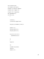
APPENDIX B
Source Code
(PIC16F84A Microcontroller)
62
void initPorts(void);
void setMotor(char myDir);
unsigned int stepCtr=0,tempSC=0;
unsigned short *myByte,ctr;
unsigned short stepperStep;
char mySendChars[7];
void main(void)
{
initPorts();
//initialize stepper motor;
Soft_Uart_Init(PORTA,1,0,9600,0);
setMotor('R');
Soft_Uart_Write('R');
Soft_Uart_Write('R');
for(ctr=0;ctr<7;ctr++)
mySendChars[ctr]=0;
do
{
stepCtr=0;
do{
if(PORTA.F1==0)break;
}while(1);
setMotor('R');
63
Soft_Uart_Write('F');
Soft_Uart_Write('F');
do{
if(PORTA.F1==0)break;
}while(1);
stepCtr=0;
setMotor('F');
IntToStr(stepCtr, mySendChars);
tempSC=stepCtr;
for(ctr=0;ctr<7;ctr++)
{
Soft_Uart_Write(mySendChars[ctr]);
Delay_ms(50);
}
}while(1);
}
void initPorts(void)
{
TRISA=0x0E;
TRISB=0xF0;
PORTA=0x00;
PORTB=0x00;
64
}
void setMotor(char myDir)
{
switch(myDir)
{
case 'R': //REVERSE
stepperStep=8;
while(1)
{
PORTB&=0xF0;
PORTB|=stepperStep;
//Delay_ms(10);
if(stepperStep==1)
stepperStep=8;
else
stepperStep=stepperStep>>1;
if(PORTA.F2==1)
{
PORTB&=0xF0;
//Delay_ms(500);
break;
}
}
65
break;
case 'F': //FORWARD
stepperStep=1;
while(1)
{
PORTB&=0xF0;
PORTB|=stepperStep;
Delay_ms(10);
if(stepperStep==8)
stepperStep=1;
else
stepperStep=stepperStep<<1;
stepCtr=stepCtr+1;
if((PORTA.F3==0) || (stepCtr==2000))
{
PORTB&=0xF0;
Delay_ms(500);
break;
}
}
break;
}
}
66
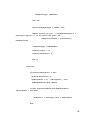
APPENDIX C
Source Code
(Ring Calibration and Finger Diameter Measurement System)
67
Private Sub mscRing_OnComm()
Dim myText As String
Select Case mscRing.CommEvent
Case comEvReceive
myText = mscRing.Input
Select Case myText
Case "RR"
If GetMyTransType = "WAITING" Then
setMyTransType ("READY")
mscRing.Output = "U"
Else
MsgBox "An Error occured while processing your
transaction." & _
vbCrLf & _
"Please restart your transaction from the beginning.",
vbApplicationModal + vbInformation, GetMyVersionID
End If
Case "FF"
If GetMyTransType = "WAITING" Then
MsgBox "Please PRESS RESET on the DEVICE.",
vbApplicationModal + vbInformation, GetMyVersionID
68
setMyTransType ("WAITING")
Exit Sub
ElseIf GetMyTransType = "READY" Then
MsgBox "Please put your " & lblMyNormalLabels(6 +
GetFinger).Caption & " on the device and press 'OK'" _
, vbApplicationModal + vbInformation,
GetMyVersionID
setMyTransType ("PROCESSING")
mscRing.Output = "U"
mscRing.RThreshold = 6
End If
Case Else
If mscRing.RThreshold > 2 Then
mscRing.RThreshold = 2
myMeasurement = 20 - (CDbl(myText) / 200)
frmWidgetMOffset.Show vbModal
If mypl.GetConvertedSize(CStr(myMeasurement),
cMeasurement) = True Then
txtMyText(7 + GetFinger).Text = cMeasurement
Else
69
MsgBox "Measurement Error. Unsupported Size." &
Chr(10) & _
"Measurement + Offset in mm: " & myMeasurement,
vbApplicationModal + vbCritical, GetMyVersionID
End If
myText = mscRing.Input
myText = ""
Else
MsgBox "An Error occured while processing your
transaction." & _
vbCrLf & _
"Please restart your transaction from the
beginning.", vbApplicationModal + vbInformation, GetMyVersionID
End If
End Select
End Select
End Sub
Private Sub optGender_Click(Index As Integer)
txtMyText(4).Text = optGender(Index).Caption
70
End Sub
Private Sub txtMyText_Click(Index As Integer)
If Index > 6 And Index < 17 Then
If MsgBox("Modify measurements for " & lblMyNormalLabels(Index
- 1).Caption & " ?", vbApplicationModal + vbInformation + vbOKCancel,
GetMyVersionID) = vbOK Then
SetFinger (Index - 7)
MsgBox "Please PRESS RESET on the DEVICE after clicking
'OK'.", vbApplicationModal + vbInformation, GetMyVersionID
setMyTransType ("WAITING")
End If
End If
End Sub
Private Sub txtMyText_GotFocus(Index As Integer)
Call mypl.TextBoxFocused(Me, Index, True)
End Sub
Private Sub txtMyText_LostFocus(Index As Integer)
Call mypl.TextBoxFocused(Me, Index, False)
71
End Sub
Private Sub btnMyButtons_Click(Index As Integer)
Select Case Index
Case 0
If CheckBlanks = False Then
MsgBox "One or more required textbox is blank. Please fill
it up before saving data.", vbCritical + vbApplicationModal,
GetMyVersionID
Exit Sub
End If
If IsNumeric(Trim$(txtMyText(17).Text)) = False Then
MsgBox "INVALID VALUE for Age.", vbCritical +
vbApplicationModal, GetMyVersionID
Exit Sub
End If
Call mypl.ModifyMydata(Me, "txtMyText", "CustomerPRF",
selectedMode, selectedID)
End Select
72
Unload Me
End Sub
'--Triggers--
Private Function CheckBlanks() As Boolean
Dim myTextboxes As Control
For Each myTextboxes In Me
If TypeOf myTextboxes Is TextBox Then
If Trim$(myTextboxes.Text) = vbNullString And
myTextboxes.Index <> 0 Then
CheckBlanks = False
Exit Function
End If
End If
Next myTextboxes
CheckBlanks = True
End Function
73
APPENDIX D
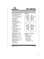
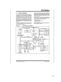
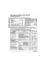
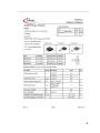
PIC16F84A Datasheet
18-Pin Enhanced FLASH/EEPROM
8-Bit Microcontroller
74
75
76
77
78
79
APPENDIX E
FS-V12 High Accuracy Fiber Optic Sensors Datasheet
Fiber Optic Proximity Sensor
80
81
82
83
84
85
86
87
88
APPENDIX F
MAX 232 Datasheet
89
90
91
92
93
94
APPENDIX G
Power Transistor Datasheet
95
96
97
98
99
100
101
102
103
104
APPENDIX H
LM7805 Voltage Regulator Datasheet
105
106
107
108
APPENDIX I
Using PIC16F84A Microcontroller in Intelligent Stepper Motor Control
109
110
111
112
113
APPENDIX J
User’s Manual
114
User’s Manual
1. Place the automatic ring sizer in its desired location.
2. Plug the device in a 220 VAC.
3. Turn on the switch.
4. Open the ring calibration and finger diameter measurement system
1.0.
5. The user must enter a username and password to access the system.
6. If procedures are done, the user can choose to exit the program by
clicking the logout button.
Data Management Menu (Customers)
1.
Select the data management from the menu and click customers.
From the customer data maintenance window,
choose the desired
operation to create a new entry, select ‗add‘ entry. To edit existing
profile, select ‗modify‘ entry. To remove an entry from the database,
select delete.
2. To close the current window, select exit.
115
To Add Entry
a. Click ‗add entry‘ button.
b. All fields must be filled up with necessary information, including
the finger sizes before saving the profile. (See Measurement
Procedures)
c. Click ‗save‘ to update the system.
d. To cancel the process, click the ‗cancel‘ button.
To Modify Entry
Select the customer‘s profile to be modified.
Click ‗modify entry‘ button.
Select the field to be edited.
Click ‗save‘ to update the system.
To cancel the process, click the ‗cancel‘ button.
To Delete Entry
Select the customer‘s profile to be deleted.
Click ‗delete‘ entry button.
The customer‘s profile window will be seen, then click ‗delete‘ to
remove the entry from the system.
To cancel the process, click the ‗cancel‘ button.
116
Data Management Menu (Rings)
1. Select the data management from the menu and click ‗Rings‘. This
window modifies the properties of every ring in the system.
2. Select the ring to be modified then click modify existing button.
3. Choose field to be edited and click ‗save‘ to update the system.
4. To cancel the process, click the ‗cancel‘ button.
Data Management Menu (Users)
1. Select the data management from the menu and click users.
This
window creates an account for the users for log in process.
2. From this window, choose the desired operation, to create a new
account, select ‗add‘ entry. To edit existing account, select ‗modify‘
entry. To remove an account from the database, select ‗delete‘.
3. To close the current window, select ‗exit‘.
To Add Account
a. Click ‗add‘ new button.
b. Enter
username
and
password.
Both
fields
can
be
alphanumeric.
c. Clicks ‗save‘ to update the system.
d. To cancel the process, click the ‗cancel‘ button.
117
To Modify Account
Select the user‘s account to be modified.
Click ‗modify existing‘ button.
Select the field to be edited.
Click ‗save‘ to update the system.
To cancel the process, click the ‗cancel‘ button.
To Delete Account
Select the user‘s account to be deleted.
Click ‗delete‘ button.
The customer‘s profile window will be seen then click ‗delete‘ to
remove the entry from the system.
To cancel the process, click the ‗cancel‘ button.
Transactions
1. Click the customer name field. A new window will be seen which shows
the list of customers stored in the system.
2. Select the name of the customer, then choose the selected finger from
the drop down menu. This will check the ring‘s availability in the
system.
3. The selected ring will display an image.
4. Click ‗close‘ to exit the window.
118
Measurement Procedures
1. Make sure that the device is switched on and the data management
window is opened simultaneously.
2. Select the finger to be measured. A new window will prompt the user
to press the reset button from the device. The user must wait for the
device to be fully stopped.
3. The system will prompt the user to insert the finger in the measurer.
The finger must be inserted properly for accurate measurements.
4. Click ‗ok‘ from the system to start measuring.
5. When the device stops, the user‘s ring size will now be displayed on
the computer.
6. Repeat step 2 until all fingers are measured.
Troubleshooting Procedures
1. No power
a. Make sure that the plug is connected to the power outlet.
b. Check the power switch if it is turned on.
2. The device does not respond to the computer.
a. Make sure that the serial data cable is connected in the device and
to the computer.
119
APPENDIX K
List of Materials and Cost
120
List of Materials and Cost
Quantity
Description
2 pcs
Fiber Optic Proximity Sensor Head
Price per
unit
Php150.00
2 pcs
Fiber Optic Proximity Sensor Amplifier
Php500.00
Php1000.00
1 pc
Unipolar Stepper Motor
Php350.00
Php350.00
1 pc
Max232 IC
Php45.00
Php45.00
3 pcs
Monolithic Capacitor 0.1µF
Php2.50
Php7.00
1 pc
DB-9 Cable Connector
Php25.00
Php25.00
1 pc
DB-9 Port
Php19.00
Php19.00
1 pc
PIC16F84A Microcontroller
Php150.00
Php150.00
6 pcs
Resistors 22KΩ
Php1.00
Php6.00
4 pcs
Resistors 400Ω
Php1.00
Php4.00
1 pc
Crystal Oscillator 4MHz
Php20.00
Php20.00
2 pcs
Electrolytic Capacitor 33pF
Php2.00
Php4.00
1 pc
Electrolytic Capacitor 0.1µF
Php2.50
Php2.50
4 pcs
MOSFET03N06
Php35.00
Php140.00
4 pcs
Diode1N4006
Php2.50
Php10.00
1 pc
Switching Mode Power Supply
Php750.00
Php750.00
1 pc
7805 Voltage Regulator
Php30.00
Php30.00
1 pc
Electrolytic Capacitor 4700µF
Php35.00
Php35.00
1 pc
Electrolytic Capacitor 1000µF
Php10.00
Php10.00
2 pcs
Push Buttons
Php20.00
Php40.00
1 pc
Power Switch
Php20.00
Php20.00
1 pc
Power Plug
Php50.00
Php50.00
1 pc
Casing
Php120.00
Php120.00
Total Price
Total
Php300.00
Php3137.50
121