1
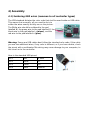
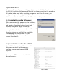
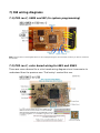
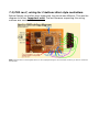
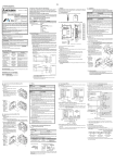
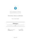
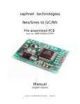
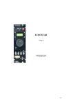
raphnet.net's
Nes/Snes/DB9 to USB
Pre-assembled PCB
(part no. #NSDB9PCB1)
User's Manual
English version
Manual no. #M_NDSB9PCB_ENG1
Table of Contents
0) Table of contents.................................................................................................2
1) Introduction.........................................................................................................3
1.1) Product summary..........................................................................................3
1.2) Supported operating Systems.......................................................................3
1.3) Supported controllers....................................................................................3
2) Getting started....................................................................................................4
2.1) What you should have received....................................................................4
2.2) Required material (not included)..................................................................4
2.3) Recommended equipment............................................................................4
2.4) Overview of installation................................................................................5
3) Controller type selection......................................................................................6
3.1) Enabling SNES mode.....................................................................................6
3.2) Enabling NES mode.......................................................................................6
3.3) Enabling DB9 mode......................................................................................6
4) Assembly.............................................................................................................7
4.1) Soldering USB wires (common to all controller types)..................................7
4.2) Soldering SNES controller wires....................................................................8
4.3) Soldering NES controller wires......................................................................8
4.4) Soldering DB9 controller wires......................................................................9
5) Installation.........................................................................................................10
5.1) Installation under Windows.........................................................................10
5.2) Installation under MacOS X.........................................................................10
5.3) Installation under Linux..............................................................................11
6) Operating notes.................................................................................................12
6.1) In SNES mode.............................................................................................12
6.2) In DB9 mode...............................................................................................12
7) Old wiring diagrams...........................................................................................13
7.1) PCB rev.C, SNES and ISP (In system programming)....................................13
7.2) PCB rev.C, color based wiring for NES and SNES........................................13
7.3) PCB rev.C, wiring for 2 buttons Atari style controllers.................................14
10) Copyright and Disclaimers...............................................................................15
10.1) Copyright..................................................................................................15
10.2) Disclaimer.................................................................................................15
10.3) Revision history.........................................................................................15
1) Introduction
1.1) Product summary
This circuit converts one of the supported game controllers to a standard USB HID
compliant input device. It can be installed inside a controller or used to build an
adapter.
1.2) Supported operating Systems
Many operating systems support USB HID joysticks. This product is known to work
with at least the following operating systems:
●
Linux kernel 2.4 and 2.6
●
Mac OS X
●
Microsoft Windows 98/ME (recent version of Direct X recommended)
●
Microsoft Windows 2000/XP/Vista
1.3) Supported controllers
●
Snes controllers and Snes mouse (auto detected)
●
Nes controllers
●
Sega Genesis 3 and 6 button controllers
●
Sega master system controllers and compatible two button joysticks such as
Amiga digital joysticks.
●
Atari 2600 one-button compatible joysticks.
2) Getting started
2.1) What you should have received
1. One PCB with 10 components installed on the Top layer, and 2 installed on
the bottom layer.
Top layer
Bottom layer
2.2) Required material (not included)
1. Soldering equipment.
2. Basic electronic tools. (cutters, wire stripper, tweezers)
3. Multimeter for testing continuity.
4. USB cable with an USB male connector (type A) on one side, and bare wires
at the opposite side. You may cut a cable in two parts to obtain this.
5. If you plan to build an adapter (instead installing the circuit inside a
controller), you will need a connector that mates with your controller. This
can come from an extension cord, a broken console, or an electronic
component store (likely for DB9 connectors).
6. Again if building an adapter, some kind of enclosure to protect the circuit is
highly recommended. This is especially important to prevent the circuit from
coming in contact with anything metallic such as a computer case. This
could cause a short circuit which could likely cause damages to the circuit or
your computer, depending on circumstances.
2.3) Recommended equipment
1. Desoldering braid (just in case)
2. Hot glue gun and Hot glue (to prevent the wires from eventually breaking at
the point where they are soldered). Especially important if the wires may
move.
2.4) Overview of installation
1. Start by carefully planning how you will install the circuit inside the
controller (or your enclosure). Make sure you dont cut the wires too short
and that the circuit wont be in the way when you put back the cover.
2. Configure the circuit for your controller type (see Chapter 3)
3. Install the USB wires (see Chapter 4, section 1)
4. Install your controller wires (see Chapter 4, section 2 and on)
5. Inspect for shorts. Double-checking with a multimeter is recommended if
you have any doubts.
6. Test on a computer. If it does not work, double check everything and then
contact me.
7. Install hot glue over the solder points.
8. Insulate any metal part (e.g. USB cable shield) which could come in contact
with the Circuit. Use electric tape or hot glue.
9. Finish the installation. (Close enclosure)
10. Play!
3) Controller type selection
The circuit supports 3 different modes (SNES, NES and DB9 mode). The mode is
selected by connecting (or not connecting) parts of JP1 and JP2. JP1 and JP2 are
checked by the firmware at power-up or reset.
3.1) Enabling SNES mode
Snes mode is enabled by not connecting anything.
3.2) Enabling NES mode
Nes mode is enabled by connecting JP1 pads together.
3.3) Enabling DB9 mode
DB9 mode (for Genesis, SMS, Atari and compatibles) is enabled by
connecting JP1 and JP2 together as shown on the picture:
4) Assembly
4.1) Soldering USB wires (common to all controller types)
The USB standard dictates the color code that shall be used inside an USB cable.
This means that normally, all you need to do is to
solder the wires exactly as they are on the picture.
The White wire should be soldered to the pad
labelled W, the green wire to the pad labelled G, the
black wire to the pad labelled – (minus), and the
red wire to the pad labelled + (plus).
Warning: Some rare USB cables dont follow the standard color code. If the cable
you use has additional wires, if any color is different, or if you have doubts, check
the pinout with a multimeter. Mis-wiring may cause damage to your computer, to
this circuit or to the controller.
Here is the standard USB pinout
Pin 1
Red
5 volts
Pin 2
White
D-
Pin 3
Green
D+
Pin 4
Black
Ground
4.2) Soldering SNES controller wires
As far as I am aware, Nintendo brand controllers all use the same
color code. Many clones also use this convention too, but not all. If
your controller uses the standard color code, you can follow the
diagram on the right. (Note that the SNES and NES color codes are
different).
If you're not sure about your controller, check it's pinout with a multimeter and
use the table and picture below for wiring:
Pin Function Standard color Connect to
1
5 volts
White
+
2
Clock
Yellow
PC5
3
Latch
Orange
PC4
4
Data
Red
PC3
7
Ground
Brown
Note: Pin numbers were arbitrarily assigned. They do not match any known
standard or convention.
4.3) Soldering NES controller wires
As far as I am aware, Nintendo brand controllers all use the same
color code. Many clones use this convention too, but not all. If your
controller uses the standard color code, you can follow the diagram
on the right. (Note that the SNES and NES color codes are different).
If you're not sure about your controller, check it's pinout with a multimeter and
use the table and picture below for wiring:
Pin Function Standard color Connect to
1
Ground
Brown
-
2
Clock
Red
PC5
3
Latch
Orange
PC4
4
Data
Yellow
PC3
7
5 volts
White
+
Note: Pin numbers were arbitrarily assigned.
They do not match any known standard or convention.
4.4) Soldering DB9 controller wires
There are too many different kind of controllers using DB9
connectors to talk about a standard color code. Fortunately,
cutting your controller cable is far from necessary in this case. It is
best to use easy to find solder cup DB9 connectors. The original
controller can thus be left intact.
The picture on the right shows where to connect each DB9 pin on
the board.
Solder cup DB9 male connectors
Here is a table summarizing what the wires are used for with different type of DB9
controllers.
Pin
Genesis 3
Genesis 6 SMS
Atari 2600
1
Up
Up or Z
Up
Up
2
Down
Down or Y
Down
Down
3
Left or 0
Left, 0 or X Left
4
Right or 0
5
Right
+5volts
6
Button A or B
7
Select
8
Ground
9
Button Start or C
Left
Right
Not used
Button 1
Fire button
Not used
+5v, 50mA max.
Button 2
Not used
5) Installation
Up to now, all operating systems this product was tested with had native support
for USB HID joysticks and gamepads. Most of the time, connecting the adapter is
all that has to be done before starting your game. (and then of course, you
configure the game to use joysticks).
But here are a few installation notes for different operating systems.
5.1) Installation under Windows
When you connect the adapter for the first time,
depending on your Windows version, a pop up
may appear requesting that you insert your
windows installation cdrom. Follow the
instructions. After installation completes, you may
be required to reboot your computer.
Once the drivers are installed, the controller
should appear in Control Panel -> Game
controllers/ Gaming options every time you
connect the adapter.
5.2) Installation under Mac OS X
No installation instruction at the moment. No
drivers are required, but the game or
emulator you use must support USB
Joysticks.
You may use USB Prober to check for the
device presence.
USB Prober
5.3) Installation under Linux
Normally, the controller will work instantly. There are too many different Linux
distributions to cover every possible scenarios, but here are a few ways to check if
the adapter was detected correctly.
After connecting your adapter, check dmesg for a message such as this one:
[1439918.730644] usb 2-2.2: new low speed USB device using uhci_hcd and address 67
[1439918.862745] usb 2-2.2: configuration #1 chosen from 1 choice
[1439918.887690] input: raphnet.net (S)NES/Atari_USB as /class/input/input75
[1439918.887749] input: USB HID v1.01 Gamepad [raphnet.net (S)NES/Atari_USB] on usb-0000:00:1a.1-2.2
Make sure the usb, input, hid and joydev modules are loaded (or compiled into
your kernel). The device should appear /proc/bus/input/devices:
# cat /proc/bus/input/devices
...
I: Bus=0003 Vendor=1781 Product=0a96 Version=0101
N: Name="raphnet.net (S)NES/Atari_USB"
P: Phys=usb-0000:00:1d.0-1.1/input0
S: Sysfs=/class/input/input72
U: Uniq=1000
H: Handlers=event3 js0
B: EV=b
B: KEY=ff0000 0 0 0 0 0 0 0 0 0
B: ABS=3
Notice the 'js0' handler above. If you have more than one controller, this could be
js1, js2... If no jsX handler is present, you need the joydev module.
For testing the buttons and directions, you can use the jstest tool. Under debian,
this is in the joystick package.
# jstest ./js0
Driver version is 2.1.0.
Joystick (raphnet.net (S)NES/Atari_USB) has 2 axes (X, Y)
and 8 buttons (BtnX, BtnY, BtnZ, BtnTL, BtnTR, BtnTL2, BtnTR2, BtnSelect).
Testing ... (interrupt to exit)
Axes:
0:
0
1:
0 Buttons:
0:off
1:off
2:off
3:off
4:on
5:off
6:off 7:off
Axes:
0:
0
1:
0 Buttons:
0:off
1:off
2:off
3:off
4:off
5:off
6:on
7:off
6) Operating notes
6.1) In SNES mode
NES controller detection
If a NES controller is connected instead of an SNES controller, it should be autodetected. Auto-detection works with original Nintendo controllers, but may be
unreliable with certain imitations. In this case, the adapter should be used in NES
mode.
Mouse support
When SNES mode is selected and an SNES mouse is connected instead of a
regular controller, the adapter will act as a standard USB mouse instead of a
joystick.
The SNES mouse supports 3 different speeds. The operating speed can be
selected:
●
High speed: Hold the right button down while connecting the mouse.
●
Medium speed: Hold the left button down while connecting the mouse.
●
Low speed: Hold the left and right buttons down while connecting the
mouse.
The default speed is 'Low'. If the mouse (but not the adapter) is disconnected
during use and re-connected later, the previous speed is used.
6.2) In DB9 mode
In this mode, the type of controller is auto-detected. At power-up (that is, when
you connect the USB side of the adapter), a test is done to decide if the
connected controller is a Genesis controller or and older SMS or Atari controller.
If no controller is connected, the adapter will think there is a two button SMS or
Atari compatible controller. If you connect a Genesis controller later, only two
buttons will work.
If a Genesis controller was detected, the adapter assumes it is a 3 button
controller. But as soon as the X, Y or Z button is pressed alone, the adapter
switches in 6 button mode. But this should be 100% transparent to the user.
7) Old wiring diagrams
7.1) PCB rev.C, SNES and ISP (In system programming)
Note: The blue wires on the diagram above are for (re)programming the microcontroller. Useful if you want to customize
the software.
7.2) PCB rev.C, color based wiring for NES and SNES
There was some demand for a color based wiring diagram since it was easier to
understand than the previous one. That's why I created this one.
7.3) PCB rev.C, wiring for 2 buttons Atari style controllers.
Before Genesis controllers were supported, the pinout was different. This was the
diagram to follow. (Important note: The last firmware supporting this wiring
scheme was version 1.4).
Note: The blue wires on the diagram above are for (re)programming the microcontroller. Useful if you want to customize
the software.
10) Copyright, Disclaimer and History
10.1) Copyright
All the information, pictures, diagrams, tables and texts contained
in this manual is Copyright Raphaël Assénat, 2007. All rights reserved. Partial or
total reproduction is not permitted without the Copyright holder's written
authorisation, except for personal use.
Trademarks that are mentioned in this manual are the property of their respective
owners.
10.2) Disclaimer
Even thought I made great efforts and a lot of testing to make sure my products
are safe, I cannot be held responsible for any damage(s) or loss(es) caused
directly or indirectly by the use of my products, including but not limited to, loss of
data, loss of profit, computer/server downtime, device and peripheral damage or
failure.
While I believe that all the information contained in this manual is accurate,
should damage occur because of an error in this manual, my responsibility will be
limited to replacing my product if it is damaged.
10.3) Revision history
November 1, 2007
First version of this manual.