1
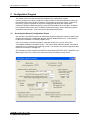
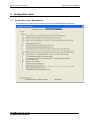
MX Compliance Test System
System Administrator Manual
MX Compliance Test System
System Administrator
Manual
MXCTSH / MXCTSL
Revision B
1
MX Compliance Test System
System Administrator Manual
SAFETY SUMMARY
These power system components contain high voltage and current circuits that are potentially
lethal. The following safety guidelines must be followed when operating or servicing this
equipment. These guidelines are not a substitute for vigilance and common sense. California
Instruments assumes no liability for the customer's failure to comply with these requirements.
APPLYING POWER AND GROUNDING
Verify the correct voltage is applied to the equipment. Verify that the input power to the PACS-3-75 unit
is plugged into a properly grounded utility outlet.
FUSES
Use only fuses of the specified current, voltage, and protection speed.
Do not short out the fuse holder or use a repaired fuse.
The PACS-3-75 unit uses a North-American ferrule type input fuse rated at 0.5A and 250Volts. (Fast
Acting)
DO NOT OPERATE IN A VOLATILE ATMOSPHERE
Do not operate the system in the presence of flammable gases or fumes.
DO NOT TOUCH ENERGIZED CIRCUITS
Disconnect power cables before servicing this equipment. Even with the power cable disconnected,
high voltage can still exist on some circuits. Discharge these voltages before servicing. Only qualified
service personnel may remove covers, replace components or make adjustments.
DO NOT SERVICE ALONE
Do not remove covers, replace components, or make adjustments unless another person, who can
administer first aid, is present.
DO NOT EXCEED INPUT RATINGS
Do not exceed the rated input voltage or frequency. Additional hazards may be introduced because of
component failure or improper operation.
DO NOT MODIFY INSTRUMENT OR SUBSTITUTE PARTS
Do not modify these instruments or substitute parts. Additional hazards may be introduced because of
component failure or improper operation.
MOVING THE POWER SOURCE
When moving the power source, observe the following:
1. Remove all AC power to system components.
2. Use two people to prevent injury.
Revision B
2
MX Compliance Test System
System Administrator Manual
CTSMXH / CTSMXL Software License
Your Compliance Test System (MXCTS) was shipped with one copy of the CTSMXH software,
CTSMXL software or both. This software - model number CIC 651 and CIC652 respectively - is
owned by California Instruments and is protected by United States copyright laws and
international treaty provisions. Therefore, you must treat the software like any other copyrighted
material.
Software Revisions
Revision codes in the Help About screen of the CTSMXH / CTSMXL software indicate the current
revision. Minor changes to the software such as bug fixes usually do not require a change to the
manual. Therefore, the revision number of the software you received with the MXCTS system
may be higher than the software revision number shown below. In this case, the information in
the manual still applies.
Software changes that require a manual change will be accompanied either by a new edition of
the manual or an errata sheet documenting the changes.
This manual applies to software revision 1.4.0.2 or higher.
Printing History
The manual printing date indicates the current edition. The printing date changes with each new
edition or update. Update packets or change sheets may be issued between editions to correct or
add information. Minor corrections incorporated at reprint do not cause a new edition.
August 2006
First Edition, Revision B
Trademarks
Windows 98™, Windows 2000™, Windows XP™, MS Word™, and MS Excel™ are registered
trademarks of Microsoft Corporation.
Contacting California Instruments
To contact California Instruments, use any of the communication channels listed here:
Mail:
California Instruments
9689 Towne Centre Drive
San Diego, CA 92121-1964
USA
Phone:
858 677 9040
7:00 AM - 4:00 PM Pacific Standard Time
Voice Mail 24 hours
Fax:
858 677-0940
Email:
[email protected]
Web site:
www.calinst.com
Revision B
3
MX Compliance Test System
System Administrator Manual
ONE YEAR WARRANTY
CALIFORNIA INSTRUMENTS CORPORATION warrants each instrument manufactured by them
to be free from defects in material and workmanship for a period of one year from the date of
shipment to the original purchaser. Excepted from this warranty are fuses and batteries that carry
the warranty of their original manufacturer where applicable. CALIFORNIA INSTRUMENTS will
service, replace, or adjust any defective part or parts, free of charge, when the instrument is
returned freight prepaid, and when examination reveals that the fault has not occurred because of
misuse, abnormal conditions of operation, user modification, or attempted user repair. Equipment
repaired beyond the effective date of warranty or when abnormal usage has occurred will be
charged at applicable rates. CALIFORNIA INSTRUMENTS will submit an estimate for such
charges before commencing repair, if so requested.
PROCEDURE FOR SERVICE
If a fault develops, notify CALIFORNIA INSTRUMENTS or its local representative, giving full
details of the difficulty, including the model number and serial number. On receipt of this
information, service information or a Return Material Authorization (RMA) number will be given.
Add RMA number to shipping label. Pack instrument carefully to prevent transportation damage,
affix label to shipping container, and ship freight prepaid to the factory. CALIFORNIA
INSTRUMENTS shall not be responsible for repair of damage due to improper handling or
packing. Instruments returned without RMA No. or freight collect will be refused. Instruments
repaired under Warranty will be returned by prepaid surface freight. Instruments repaired outside
the Warranty period will be returned freight collect, F.O.B. CALIFORNIA INSTRUMENTS 9689
Towne Centre Drive, San Diego, CA 92121-1964. If requested, an estimate of repair charges
will be made before work begins on repairs not covered by the Warranty.
DAMAGE IN TRANSIT
The instrument should be tested when it is received. If it fails to operate properly, or is damaged
in any way, a claim should be filed immediately with the carrier. A full report of the damage
should be obtained by the claim agent, and a copy of this report should be forwarded to us.
CALIFORNIA INSTRUMENTS will prepare an estimate of repair cost and repair the instrument
when authorized by the claim agent. Please include model number and serial number when
referring to the instrument.
Revision B
4
MX Compliance Test System
System Administrator Manual
LIMITATION OF WARRANTY
California Instruments believes the information contained in this manual is accurate. This document has
been carefully reviewed for technical accuracy. In the event that technical or typographical errors exist,
California Instruments reserves the right to make changes to subsequent editions of this document
without prior notice to holders of this edition. The reader should consult California Instruments if errors are
suspected. In no event shall California Instruments be liable for any damages arising out of or related to
this document or the information contained in it.
CALIFORNIA INSTRUMENTS PROVIDES NO WARRANTIES, EXPRESS OR IMPLIED, AND
SPECIFICALLY DISCLAIMS ANY WARRANTY OF MERCHANTABILITY OR FITNESS FOR A
PARTICULAR PURPOSE OF THIS SOFTWARE AND DOCUMENTATION. CALIFORNIA
INSTRUMENTS WILL NOT BE LIABLE FOR DAMAGES RESULTING FROM LOSS OF DATA,
PROFITS, USE OF PRODUCTS, OR INCIDENTAL OR CONSEQUENTIAL DAMAGES, EVEN IF
ADVISED OF THE POSSIBILITY THEREOF.
This limitation of liability of California Instruments will apply regardless of the form of action, whether in
contract or tort, including negligence. The warranty provided herein does not cover damages, defects,
malfunctions, or service failures caused by owner’s failure to follow California Instruments’ installation,
operation, or maintenance instructions; owner’s modification of the product; owner’s abuse, misuse, or
negligent acts; and power failures, surges, fire, flood, accident, actions of third parties, or other events
outside reasonable control.
SOME STATES DO NOT ALLOW LIMITATIONS ON THE LENGTH OF AN IMPLIED WARRANTY OR
THE EXCLUSION OR LIMITATION OF INCIDENTAL OR CONSEQUENTIAL DAMAGES, SO THE
ABOVE LIMITATION OR EXCLUSIONS MAY NOT APPLY TO YOU. THIS WARRANTY GIVES YOU
SPECIFIC LEGAL RIGHTS, AND YOU MAY ALSO HAVE OTHER RIGHTS WHICH VARY FROM
STATE TO STATE.
If any part of this Agreement shall be determined by a court to be invalid, illegal or unenforceable, the
remaining provisions shall in no way be affected or impaired thereby.
GOVERNING LAW. This Agreement and Limited Warranty are governed by the laws of the state of
California without regard to conflict of law provisions.
INSTALLATION AND / OR USE OF THIS PROGRAM CONSTITUTES ACCEPTANCE OF THESE
TERMS AND RESTRICTIONS BY THE USER.
© 1997 - 2006 COPYRIGHT
Under the copyright laws, this publication may not be reproduced or transmitted in any form, electronic or
mechanical, including photocopying, recording, storing in an information retrieval system, or translating, in
whole or in part, without the prior written consent of California Instruments Corporation.
California Instruments Corporation, © 1997 - 2006
Warning regarding Medical and Clinical use of California
Instruments products.
California Instruments products are not designed with components and testing intended to ensure a level
of reliability suitable for use in the treatment and diagnosis of human beings. California Instruments
products are NOT intended to be used to monitor or safeguard human health and safety in medical or
clinical treatment and California Instruments assumes no responsibility for this type of use of its products
or software.
Revision B
5
MX Compliance Test System
System Administrator Manual
Table of Contents
1
Introduction .......................................................................................................................................... 7
2
Configuration Program........................................................................................................................ 8
2.1
2.2
2.3
2.4
2.5
2.6
3
Configuration Limits.......................................................................................................................... 13
3.1
3.2
3.3
3.4
3.5
4
Accessing the General Configuration Screen ................................................................................ 8
Password ........................................................................................................................................ 9
Changing General Configuration Settings...................................................................................... 9
Changing Hidden Configuration Settings ....................................................................................... 9
Configuration Option Selection - CTSMXL................................................................................... 10
Configuration Option Selection - CTSMXH .................................................................................. 11
Configuration Limits - Miscellaneous............................................................................................ 13
Configuration Limits - Voltage Distortion ...................................................................................... 19
Configuration Limits - Transitory State Harmonics - CTSMXL ..................................................... 20
Configuration Limits - Transitory State Harmonics - CTSMXH .................................................... 21
Configuration Limits - Flicker ........................................................................................................ 22
Measurement Uncertainty................................................................................................................. 23
4.1
4.2
4.3
4.4
4.5
Introduction ................................................................................................................................... 23
ISO/IEC 17025:1999 Standard..................................................................................................... 23
Statements of Compliance - Effect of Uncertainty........................................................................ 24
Uncertainty of the MXCTS System............................................................................................... 24
Adding Uncertainty Information to MXCTS Test Reports............................................................. 26
Table of Tables
Table 4-1: CTS Measurement Uncertainty - Harmonics............................................................................. 25
Table 4-2: CTS Measurement Uncertainty - Flicker ................................................................................... 26
Revision B
6
MX Compliance Test System
System Administrator Manual
1 Introduction
This manual is intended for the system administrator of the MX45-3Pi-CTSH and MX45-3Pi-CTSL
compliance test systems. Several aspects of the CTSMXH/L software operation can be set using
the configuration module. This includes IEC test limits, modes of operation, feature selection etc.
These settings are password protected to ensure that no changes by unauthorized personnel are
made. As a system administrator however, you have the option of changing any aspect of the
MXCTS configuration.
Note that doing so may invalidate the compliance to existing IEC test standards. The MXCTS
system is shipped with all parameters set to comply with prevailing IEC standards at the time of
shipment. Making changes to any of these password-protected features is done solely at your
own risk.
The following aspects of the CTSMXH/L software operation can be changed using the
Ctsmxl_config.exe or the Ctsmxh_config.exe program:
•
EN/IEC Harmonics Limits for class A, B, C and D. - (CTSMXL only)
•
EN/IEC Harmonics Limits for Stage 1 and Stage 2 connections. (CTSMXH only)
•
EN/IEC Flicker transfer function for 50 Hz and 60 Hz flicker operation
•
EN/IEC Flicker test limits for Pst, dc, dt and dmax
•
Source voltage distortion limits for IEC harmonics test
•
Miscellaneous parameters
All parameters and settings are stored in the test_summary.mdb database located in the
database subdirectory. The CTSMXL and CTSMXH programs each maintain there own
database in their own sub directories. These databases are NOT interchangeable. Changes are
time stamped and the user name is logged with the changes for audit purposes. Do not attempt to
edit this database in any other way than using the supplied Ctsmxl_config.exe or
Ctsmxh_config.exe programs. If this database gets corrupted, the main CTSMXH/L program will
not function.
Revision B
7
MX Compliance Test System
System Administrator Manual
2 Configuration Program
The chapter covers the various setup tabs available in the configuration program
(Ctsmxh_config.exe or Ctsmxl_config.exe). It also provides the required instructions to bring up
the protected area of the Config.exe program. The operator may use the Ctsmxl_config.exe or
the Ctsmxh_config.exe program at any time to display general setup and configuration
information. Without a password however, none of this information can be changed. In addition
to this general setup screen, there are hidden screens that may be used to change key system
parameters and test limits. These screens are also password protected.
2.1
Accessing the General Configuration Screen
Any operator of the MXCTS system can access the general configuration screen by selecting the
program shortcut for the Configuration program from the Windows Start menu. This shortcut is
located in the CTSMXH or CTSMXL program group.
Once a user name is provided (optional for read-only access), the user can click on the
"View/Update calibration information" button. The screen shown below will appear. Note that no
password entry is required to gain read-only access. The operator can review configuration data
shown but can make no changes to it.
This information is also covered by the MXCTSH User Manual (P/N 7003- 972) or MXCTSL User
Manual (P/N 7003- 973). Refer to this manual for further information on this screen.
Revision B
8
MX Compliance Test System
2.2
System Administrator Manual
Password
The configuration password is shown here. Note that this password is not case sensitive.
Cal_lock
2.3
Changing General Configuration Settings
Open the Configuration program as described before. After entering your name, enter the
password in the password entry box. Then click on the "View/Update calibration information"
button. The same configuration data will be shown only this time, changes can be made. When
the configuration screen is closed, all changes made are stored in the test_summary.mdb
database along with the login name and date.
This information is also covered by the MXCTSH User Manual (P/N 7003- 972) or MXCTSL User
Manual (P/N 7003- 973). Refer to this manual for further information on this screen.
2.4
Changing Hidden Configuration Settings
Open the Configuration program as described before. After entering your name, enter the
password in the password entry box. Then double-click on the empty space between the
"View/Update calibration information" and the "Cancel and exit program" button. This will reveal
a hidden button labeled "View/Update limit information". Next click on this hidden button to bring
up the hidden configuration data screen. When the configuration screen is closed, all changes
made are stored in the test_summary.mdb database along with the login name and date.
Revision B
9
MX Compliance Test System
2.5
System Administrator Manual
Configuration Option Selection - CTSMXL
The configuration screen is shown below. The drop down control at the top of the Configuration
window can be used to access any one of the following limit sections:
•
Miscellaneous parameters and test limits
•
Voltage source qualification limits
•
Class A, B, C or D limits
•
Flicker Limits
Revision B
10
MX Compliance Test System
2.6
System Administrator Manual
Configuration Option Selection - CTSMXH
The configuration screen is shown below. The drop down control at the top of the Configuration
window can be used to access any one of the following limit sections:
•
Miscellaneous parameters and test limits
•
Voltage source qualification limits
•
Stage 1 and 2 Harmonics limits for various Rsce and phase configurations
•
Flicker Limits
Revision B
11
MX Compliance Test System
System Administrator Manual
Page intentionally left blank
Revision B
12
MX Compliance Test System
System Administrator Manual
3 Configuration Limits
3.1
Configuration Limits - Miscellaneous
The Miscellaneous screen provides access to the following test limit database parameters:
Revision B
13
MX Compliance Test System
3.1.1
System Administrator Manual
For Harmonics
Field
Description
Start Phase
Sets the phase angle for the start of each data window processed. The default
start phase angle is 0 degrees. This ensures synchronization to the EUT
voltage and current data.
Fail window code
Data is acquired in windows of 10, 12 or 16 signal periods. If the data for a
given window exceeds the test limits, the data for this window can be stored in
its entirety (value set to 0) or only a fraction of the window can be saved.
(value set > 0).
Normally, this field should be set to 0.
Data Storage
Number of saves, first
section
This number represents the number of acquisition window (buffers) to save for
this first portion of the test. If the test time is set to a lower value than this, all
buffers are saved for the entire test. If the total test time exceeds this value
times the buffer duration - 16, 12 or 10 cycles at the specified frequency - the
remainder of the test (last section), data will be saved at a lower rate
determined by the number in the next field.
An acquisition window is either 16, 12 or 10 periods long. The period is
determined by the selected frequency (50, 60 or 400 Hz).
For example, if this value is set to 2000 at 16 cycles of 50 Hz, this corresponds
to 2000 * 16 * 20 msec = 640 secs.= 10 min 40 sec. If the test time is less
than this, all buffers are saved. If the test time is 12 minutes, the last 20
seconds are considered the last section of the test. Not all buffers may be
saved during this last section.
Number of saves, last
section
Once every acquisition buffer during the first section has been saved, as
specified by the previous field, data recording continues at a reduced rate. The
CTSMX software will determine the remaining test time, divide it by the value
specified in this field and round the result down to the nearest integer (n).
From this moment forward, every nth buffer will be saved only, unless a failure
occurs. See next field for failure mode save.
For example, if this value is set to 1000 and the remaining test time after the
first section is 30 minutes or 1800 secs, of the 5625 buffers of 320 msec in this
th
30 minute period, every Round(5625/1000) = 5 buffer would be saved for a
total of 1000 + buffers.
Total number of saves
If a failure occurs during the second phase of the test - determined by the
previous settings - this number of buffers will be saved around the failure
buffer. This value always includes two buffers before the buffer with a failure,
the failure buffer itself, and the remaining number of buffers after the failure.
Thus, if this field is set to 8, 2 pre failure, 1 failure and 5 post failure buffers are
saved. If additional failure buffers are found during this interval, saving
continues until 5 failure free buffers are encountered or the test reaches the
end time.
Revision B
14
MX Compliance Test System
Field
System Administrator Manual
Description
Tolerances
V distortion Margin
Determines the tolerance band for the V distortion (in percent above the 100
% limit). The CTSMXH/L software will display Marginal instead of OK for the V
distortion if the distortion is between 100 % and 100 + this setting of the
allowable limit. This value is normally set to 10%. A marginal VTHD is shown
as V??? in the VTHD field.
Frequency variation
The tolerance for the detected AC Source voltage frequency. If a California
Instruments AC source is used, the frequency will be within 0.01 Hz. However,
if the AC line is used instead, frequency variations may exceed the set
tolerance in this field. If an unacceptable line frequency is detected, an error
message will be issued to the operator.
Voltage variation
The tolerance for the detected AC Source RMS voltage. If a California
Instruments AC source is used, the RMS voltage will be well within this
tolerance. However, if the AC line is used instead, voltage variations may
exceed the set tolerance in this field. If an unacceptable line voltage is
detected, an error message will be issued to the operator.
Class A/D Envelope limit
(CTSMXL only)
The amount of current waveform that is allowed to be outside the Class D
current template. This template is used to determine Class A or D EUT's.
Presently, this value is fixed by the EN 61000-3-2 Harmonics standard at 5 %.
Noise Margin
The noise floor for voltage and current measurements. If the measured input
signal is below this threshold, a warning is issues to the operator as the
signals are too weak to be measured accurately. This is normally due to
improper connection or a failure to apply the test voltage when manual source
control has been selected.
Absolute lower current
harmonic
The absolute threshold below which current harmonics are ignored per the EN
61000-3-2 and -3-12 standard. Presently, this value is 5 mA (0.005 A).
Relative lower current
harmonic
The relative (% of fundamental current) threshold below which current
harmonics are ignored per the EN 61000-3-2 and -3-12 standard.
Graph Display Modes
Fundamental display
If 0, the fundamental is not graphed. If > 0, both fundamental and harmonics
are graphed. Default value is 0.
Harmonics Filtering
If 0, transitory harmonics will be filtered using the 1.5 sec smoothing filter.
Default value is 0. If value > 0, filtering is disabled.
Class A/D Limits
(CTSMXL only)
Min. Power for Class D
This determines the lowest active power level of the EUT at which the product
is considered class D. If the power drops below this level, either no limits are
applied (EUT always passes) or class A limits are applied as the product
becomes class A. This is determined by the "min class D power will be class
A" setting. EN 61000-3-2 Standard calls out 75 W for this value.
Max. Power for Class D
Maximum power below which a product is considered class D. Other criteria
are the special current wave shape for the 1998 standard or the product type
(PC, PC monitor or TV) for the 2000 standard. EN 61000-3-2 Standard calls
out 600 W for this value.
Min class D power will be
class A
If set to 1, class A limits will be applied to the EUT if the power level falls below
the lower power limit and class D was selected by the user. If set to 0 (default),
no limits will be applied below the low power level and the EUT will always
pass. This field only applies when using the old EN 61000-3-2:1998 standard.
Initial pre-filter time (sec)
This field is not used in the CTS SW and should be left at 0.
Revision B
15
MX Compliance Test System
System Administrator Manual
Field
Description
Harmonics calibration
coefficient.
Correction factor (in percent) used to compensate for frequency roll-off (if any)
at highest current harmonics.
Voltage Compensation
When on (set to 1), the CTS software will compensate for the effect of high
voltage distortion on the current harmonics measurements, if the VTHD is
found to be over the IEC limit, before applying the IEC test limits. This setting
should always be on (1).
Revision B
16
MX Compliance Test System
3.1.2
System Administrator Manual
For Flicker
Field
Description
Start Phase
See Harmonics
Fail window code
See Harmonics
Data Storage
Number of saves, first
section
See Harmonics
Number of saves, last
section
See Harmonics
Initial Buffer
Number of acquisition periods over which to determine steady state
condition.
Tolerances
Vrms Threshold
Minimum change in voltage required to be considered a voltage change. This
is effectively a noise threshold setting. Changes below the threshold value
are not considered as actual changes but noise.
Dc threshold
The low end cut off change for dc calculation
Limit or Min/Max
If this field is 0, min/max values for frequency, voltage and voltage deviation
are plotted.
Revision B
17
MX Compliance Test System
Field
System Administrator Manual
Description
If this field is non-0, the limits for these parameters are plotted instead.
Frequency margin
Limit (in Hz) for acceptable frequency deviation. Changes in frequency below
this value are acceptable. Above this threshold, a warning is displayed.
Voltage limit
The average RMS value of each acquisition window (buffer) should not be
different by more than this value from the specified nominal RMS voltage
value. (Typically 230 V or 115 V). If the difference exceeds this setting, the
buffer is considered to be a Failed buffer. This event is flagged in the V
distortion field on the main window but does not cause the test to abort.
Deviation limit
A particular half cycle RMS should not be different by more than this value (in
%) from the RMS of the reference waveform acquired at the beginning of a
test. This limit applies only to Flicker tests. Normally, this value is set to 10 %
as normal voltage variations in RMS should not be this high. This event is
flagged but does not cause the test to abort.
Flicker Limits
Plt limit
Pass / Fail limit for Long term flicker index Plt
Pst limit
Pass / Fail limit for Short term flicker index Pst
Dc limit
Pass / Fail limit for dc
Dmax limit
Pass / Fail limit for dmax
Dt limit
Pass / Fail limit for dt
Time dt exceeded
This is maximum time for which dt may exceed the dt limit. The default value
for this parameter is 500 msec.
Flicker normalization
This is a normalization scale factor that may be applied to the final Pst result.
This value is normally 1.
Impedance
PCTS Impedance R
Not applicable to MXCTS system
PCTS Impedance L
Not applicable to MXCTS system
Flicker Inrush Test
Threshold Current
This field sets the threshold for detecting a current from an EUT off condition
used during the 24 x Dmax test. Until the current measured exceeds this
absolute level in Amps, the system will assume the EUT has not been turned
on yet. This threshold prevents false triggering on noise occurring on the
input while the EUT is in the OFF state.
Revision B
18
MX Compliance Test System
3.2
System Administrator Manual
Configuration Limits - Voltage Distortion
During current harmonics testing, the voltage distortion of the AC Source or Line voltage is
constantly monitored by the MXCTS system. The EN 61000-2-3 and EN 61000-3-12 voltage
distortion test limits are displayed in this screen and can be modified if and when a new standard
is issued that applies different limits. The measured voltage distortion is used by the software to
compensate for any distortion that may occur as a result of the EUT harmonic currents.
The data is shown in percentage of the fundamental. This 0.1 is equivalent to 0.1 % of the
fundamental voltage at 50 or 60 Hz. The limits shown are applied to the measured voltage
harmonics. The maximum number of harmonics supported is 50 but only 40 are covered by the
EN 61000-3-2 and EN 61000-3-12 standards.
Note that as of this date, the harmonic voltage distortion limits for IEC 61000-3-12 have not been
established as the test standard has not been published yet. It may be necessary to change the
data in the CTSMXH database once final limits have been established.
Harmonics for which no limit applies are set to zero.
Revision B
19
MX Compliance Test System
3.3
System Administrator Manual
Configuration Limits - Transitory State Harmonics - CTSMXL
This screen displays the transitory state current harmonic limits applied in percent of the
fundamental current or in mA per Watt for the special case of class D. Note that each EUT class
has a corresponding limit screen.
The maximum number of harmonics supported is 50 but only 40 are covered by the EN 61000-32 standard. Harmonics for which no limit applies are set to zero. For the special case of Class D,
the minimum power level of the EUT that requires testing is set to 75 Watt. This lower limit can
be changed in the harmonics configuration screen if desired. See paragraph 3.1.1.
Revision B
20
MX Compliance Test System
3.4
System Administrator Manual
Configuration Limits - Transitory State Harmonics - CTSMXH
This screen displays the Stage 2 Conditional Supply non balanced three phase (CSPNBTPE)
equipment permissible current harmonic limits. Note that each EUT Stage and type has a
corresponding limit screen.
The following connection types are supported using the abbreviations shown in the table:
Abbreviation
Meaning
CSPNBTPE
Connection Single Phase & Non Balanced Three Phase Equipment
CBTPE
Connection Balanced Three Phase Equipment
CBTPEUSC
Connection Balanced Three Phase Equipment Under Specified Conditions.
Table 3-1: Connection Type Abbreviations
If different Sce values apply to each category EUT, they will be shown between brackets
immediately following these abbreviations in the Limit drop down control.
The maximum number of harmonics supported is 50 but only 13 are presently covered by the IEC
61000-3-12 standard. Harmonics for which no limit applies are set to zero.
Revision B
21
MX Compliance Test System
3.5
System Administrator Manual
Configuration Limits - Flicker
This screen
displays the
Flicker
impression
index curve per
the IEC 868
Flicker meter
standard. A
different curve
exists for 50 Hz
and 60 Hz
flicker
measurements.
This data
should only be
changed when
changes are
made to the EN
61000-3-3 or
IEC 61000-3-11
standard.
Revision B
22
MX Compliance Test System
System Administrator Manual
4 Measurement Uncertainty
4.1
Introduction
Uncertainty is associated with the result of a measurement (eg a calibration or test) and defines
the range of the values that could reasonably be attributed to the measured quantity. When
uncertainty is evaluated and reported in a specified way, it indicates the level of confidence that
the value actually lies within the range defined by the uncertainty interval.
Any measurement is subject to imperfections; some of these are due to random effects, such as
short-term fluctuations in temperature, humidity and air-pressure or variability in the performance
of the measurer. Repeated measurements will show variation because of these random effects.
Other imperfections are due to the practical limits to which correction can be made for systematic
effects, such as offset of a measuring instrument, drift in its characteristics between calibrations,
personal bias in reading an analogue scale or the uncertainty of the value of a reference
standard.
Often, a result is compared with a limiting value defined in a specification or regulation. In this
case, knowledge of the uncertainty shows whether the result is well within the acceptable limits or
only just makes it. Occasionally a result is so close to the limit that the risk associated with the
possibility that the property that was measured may not fall within the limit, once the uncertainty
has been allowed for, must be considered.
Suppose that a customer has the same test done in more than one laboratory, perhaps on the
same sample, more likely on what they may regard as an identical sample of the same product.
Would we expect the laboratories to get identical results? Only within limits, we may answer, but
when the results are close to the specification limit, it may be that one laboratory indicates failure
whereas another indicates a pass. From time to time accreditation bodies have to investigate
complaints concerning such differences. This can involve much time and effort for all parties,
which in many cases could have been avoided if the uncertainty of the result had been known by
the customer.
4.2
ISO/IEC 17025:1999 Standard
The standard ISO/IEC 17025:1999 [General requirements for the competence of testing and
calibration laboratories] specifies requirements for reporting and evaluating uncertainty of
measurement. The problems presented by these requirements vary in nature and severity
depending on the technical field and whether the measurement is a calibration or test.
Calibration is characterized by the facts that
(i)
Repeated measurements can be made
(ii)
Uncertainty of reference instruments is provided at each stage down the calibration
chain, starting with the national standard and
(iii)
Customers are aware of the need for a statement of uncertainty in order to ensure that
the instrument meets their requirements.
Consequently, calibration laboratories are used to evaluating and reporting uncertainty. In
accredited laboratories the uncertainty evaluation is subject to assessment by the accreditation
body and is quoted on calibration certificates issued by the laboratory.
The situation in testing, in particular IEC compliance testing, is not as well-developed and
particular difficulties are encountered. In some cases a test may not be defined well enough by
the standard, leading to potentially inconsistent application and thus another source of
Revision B
23
MX Compliance Test System
System Administrator Manual
uncertainty. Such was the case with the 1998 IEC 61000-3-2 class D harmonic current limits. In
many tests there will be uncertainty components that need to be evaluated on the basis of
previous data and experience, in addition to those evaluated from calibration certificates and
manufacturers, specifications.
Accreditation bodies are responsible for ensuring that accredited laboratories meet the
requirements of ISO/IEC 17025. The standard requires appropriate methods of analysis to be
used for estimating uncertainty of measurement.
4.3
Statements of Compliance - Effect of Uncertainty
This is a difficult area and what is to be reported must be considered in the context of the client's
needs. In particular, consideration must be given to the possible consequences and risks
associated with a result that is close to the specification limit. The uncertainty may be such as to
raise real doubt about the reliability of pass/fail statements. When uncertainty is not taken into
account, then the larger the uncertainty, the greater are the chances of passing failures and
failing passes. Using better equipment, better control of environment, and ensuring consistent
performance of the test usually attains a lower uncertainty.
For some products it may be appropriate for the user to make a judgement of compliance, based
on whether the result is within the specified limits with no allowance made for uncertainty. This is
often referred to as shared risk, since the end user takes some of the risk of the product not
meeting specification. The implications of that risk may vary considerably. Shared risk may be
acceptable in non-safety critical performance, for example the EMC characteristics of a domestic
radio or TV. However, when testing a heart pacemaker or components for aerospace purposes,
the user may require that the risk of the product not complying has to be negligible and would
need uncertainty to be taken into account. An important aspect of shared risk is that the parties
concerned agree on the uncertainty that is acceptable; otherwise disputes could arise later.
4.4
Uncertainty of the MXCTS System
Uncertainty is a consequence of the unknown sign of random effects and limits to corrections for
systematic effects and is therefore expressed as a quantity, ie an interval about the result. It is
evaluated by combining a number of uncertainty components. The components used in the
MXCTS system were quantified by a combination of evaluation of the results of several repeated
measurements and by estimation based on technical data provided by the original manufacturers
of the components used in the MXCTS system.
The result of this analysis yields the accuracy specification of the MXCTS measurement system,
in particular that of the current harmonic measurement system. Software calibration coefficients
are used extensively to allow calibration of each individual measurement channel. The resulting
accuracy specification is a worst-case specification, meaning that typical MXCTS systems will
perform better. To ensure compliance of each MXCTS system to these measurement
specifications, each MXCTS system is individually tested before delivery using commonly
accepted measurement methods and NIST traceable calibration equipment.
The MXCTS accuracy specifications as published in the MXCTSH and MXCTSL User Manual
form the basis of the uncertainty assessment. The method of combining the uncertainty
components is aimed at producing a realistic rather than pessimistic combined uncertainty. This
usually means working out the square root of the sum of the squares of the separate components
(the root sum square method). The combined standard uncertainty may be reported as it stands
(the one standard deviation level), or, usually, an expanded uncertainty is reported. This is the
combined standard uncertainty multiplied by what is known as a coverage factor. The greater this
factor the larger the uncertainty interval and, correspondingly, the higher the level of confidence
that the value lies within that interval.
The uncertainty specified for the MXCTS system in the tables below uses a coverage factor of 2,
which corresponds to a confidence level of approximately 95%.
Revision B
24
MX Compliance Test System
4.4.1
System Administrator Manual
MXCTS Uncertainty - Harmonics1:
4 A RMS Range
Frequency
Uncertainty
RMS current
Fundamental current
Harmonic current
16 A RMS Range
4 mA
50 / 60 Hz
4 mA
100 Hz- 1000 Hz
0.2 % Reading + 4 mA
1050 Hz - 2000 Hz
0.2 % Reading + 6 mA
2050 Hz - 2400 Hz
0.2 % Reading + 8 mA
Frequency
Uncertainty
RMS current
Fundamental current
Harmonic current
40 A RMS Range
16 mA
50 / 60 Hz
16 mA
100 Hz- 1000 Hz
0.2 % Reading + 4 mA
1050 Hz - 2000 Hz
0.2 % Reading + 6 mA
2050 Hz - 2400 Hz
0.2 % Reading + 8 mA
Frequency
Uncertainty
RMS current
Fundamental current
Harmonic current
75 A RMS Range
32 mA
50 / 60 Hz
32 mA
100 Hz- 1000 Hz
0.2 % Reading + 4 mA
1050 Hz - 2000 Hz
0.2 % Reading + 6 mA
2050 Hz - 2400 Hz
0.2 % Reading + 8 mA
Frequency
Uncertainty
RMS current
Fundamental current
Harmonic current
64 mA
50 / 60 Hz
64 mA
100 Hz- 1000 Hz
0.2 % Reading + 4 mA
1050 Hz - 2000 Hz
0.2 % Reading + 6 mA
2050 Hz - 2400 Hz
0.2 % Reading + 8 mA
Table 4-1: MXCTS Measurement Uncertainty - Harmonics
1
Uncertainty data is given for products under test that exhibit a Power Factor of 0.75 < PF or PF < - 0.75.
Revision B
25
MX Compliance Test System
4.4.2
System Administrator Manual
MXCTS Uncertainty - Flicker2:
Flicker
Uncertainty
Pst
5 % Reading
Plt
5 % Reading
dc
5 % Reading
dt
5 % Reading
dmax
5 % Reading
Table 4-2: MXCTS Measurement Uncertainty - Flicker
4.5
Adding Uncertainty Information to MXCTS Test Reports
If desired, the uncertainty information regarding the CTS measurement system may be added to
the test reports generated by the CTSMXH or L software. To do so, edit the report templates
located in the "C:\Program Files\California Instruments\Ctsmxh\report_files\templates" or
"C:\Program Files\California Instruments\Ctsmxl\report_files\templates" subdirectory. Use the
File, Open menu in MS Word and select any of the Hnnnnnn.doc or HA14nnnnn.doc (for
Harmonics reports) or F1000000.doc or F300000.doc (for Flicker) report templates.
Add a page at the end to the report containing the table information above and save the
templates as MS Word docs under the same name. You may want to save the original template
docs under a different name before doing so.
Once updated, future reports will automatically include this information.
2
Uncertainty data is given for products under test that exhibit a Power Factor of 0.75 < PF or PF < - 0.75.
Revision B
26
MX Compliance Test System
System Administrator Manual
Index
Manual
Administrator .........................................7
History............................................. 3
Configuration
Changing.........................................9
Password............................................... 9
General ...........................................8
Printing .................................................. 3
Hidden.............................................9
report templates .................................. 26
Contents .................................................6
Software
Copyright ...............................................5
License ............................................ 3
Database ...............................................7
Revision .......................................... 3
Software license ..................................... 3
Flicker
Limits.............................................22
Uncertainty .......................................... 23
Settings ........................................17
Voltage
Harmonics
Distortion....................................... 19
Limits.......................................20, 21
Warranty................................................ 5
Settings .........................................13
ISO/IEC 17025 ..............................23, 24
Revision B
27