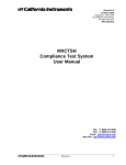
1
MX Series
AC and DC Power Source
Installation Manual
Contact Information
Telephone: 800 733 5427 (toll free in North America)
858 450 0085 (direct)
Fax: 858 458 0267
Email:
Domestic Sales: [email protected]
International Sales: [email protected]
Customer Service: [email protected]
Web: www.programmablepower.com
March 2011
Document No. 7003-968 Rev. D
Installation Manual
AC Power Source
California Instruments
Models:
MX45-1
MX45-3
MX45-3Pi
MX90-3
MX90-3Pi
MX90-3Pi-MB
MX135-3
MX135-3Pi
MX135-3Pi-MB
Rev C, June 2008.
About AMETEK
AMETEK Programmable Power, Inc., a Division of AMETEK, Inc., is a global leader in the design
and manufacture of precision, programmable power supplies for R&D, test and measurement,
process control, power bus simulation and power conditioning applications across diverse
industrial segments. From bench top supplies to rack-mounted industrial power subsystems,
AMETEK Programmable Power is the proud manufacturer of Elgar, Sorensen, California
Instruments and Power Ten brand power supplies.
AMETEK, Inc. is a leading global manufacturer of electronic instruments and electromechanical
devices with annualized sales of $2.5 billion. The Company has over 11,000 colleagues working
at more than 80 manufacturing facilities and more than 80 sales and service centers in the United
States and around the world.
Trademarks
AMETEK is a registered trademark of AMETEK, Inc.
Other trademarks, registered trademarks, and product names are the property of their respective
owners and are used herein for identification purposes only.
Notice of Copyright
MX Series AC and DC Power Source, Installation Manual © 2010 AMETEK Programmable Power,
Inc. All rights reserved.
Exclusion for Documentation
UNLESS SPECIFICALLY AGREED TO IN WRITING, AMETEK PROGRAMMABLE POWER, INC.
(“AMETEK”):
(a) MAKES NO WARRANTY AS TO THE ACCURACY, SUFFICIENCY OR SUITABILITY OF ANY
TECHNICAL OR OTHER INFORMATION PROVIDED IN ITS MANUALS OR OTHER
DOCUMENTATION.
(b) ASSUMES NO RESPONSIBILITY OR LIABILITY FOR LOSSES, DAMAGES, COSTS OR
EXPENSES, WHETHER SPECIAL, DIRECT, INDIRECT, CONSEQUENTIAL OR INCIDENTAL,
WHICH MIGHT ARISE OUT OF THE USE OF SUCH INFORMATION. THE USE OF ANY SUCH
INFORMATION WILL BE ENTIRELY AT THE USER’S RISK, AND
(c) REMINDS YOU THAT IF THIS MANUAL IS IN ANY LANGUAGE OTHER THAN ENGLISH,
ALTHOUGH STEPS HAVE BEEN TAKEN TO MAINTAIN THE ACCURACY OF THE
TRANSLATION, THE ACCURACY CANNOT BE GUARANTEED. APPROVED AMETEK CONTENT
IS CONTAINED WITH THE ENGLISH LANGUAGE VERSION, WHICH IS POSTED AT
WWW.PROGRAMMABLEPOWER.COM.
Date and Revision
March 2011 Revision D
Part Number
7003-968
Contact Information
Telephone:
Fax:
Email:
Web:
800 733 5427 (toll free in North America)
858 450 0085 (direct)
858 458 0267
[email protected]
[email protected]
www.programmablepower.com
i
This page intentionally left blank.
ii
Important Safety Instructions
Before applying power to the system, verify that your product is configured properly for your
particular application.
Hazardous voltages may be present when covers are removed. Qualified
personnel must use extreme caution when servicing this equipment.
Circuit boards, test points, and output voltages also may be floating above
WARNING (below) chassis ground.
The equipment used contains ESD sensitive ports. When installing
equipment, follow ESD Safety Procedures. Electrostatic discharges might
cause damage to the equipment.
WARNING
Only qualified personnel who deal with attendant hazards in power supplies, are allowed to perform
installation and servicing.
Ensure that the AC power line ground is connected properly to the Power Rack input connector or
chassis. Similarly, other power ground lines including those to application and maintenance
equipment must be grounded properly for both personnel and equipment safety.
Always ensure that facility AC input power is de-energized prior to connecting or disconnecting any
cable.
In normal operation, the operator does not have access to hazardous voltages within the chassis.
However, depending on the user’s application configuration, HIGH VOLTAGES HAZARDOUS TO
HUMAN SAFETY may be normally generated on the output terminals. The customer/user must
ensure that the output power lines are labeled properly as to the safety hazards and that any
inadvertent contact with hazardous voltages is eliminated.
Guard against risks of electrical shock during open cover checks by not touching any portion of the
electrical circuits. Even when power is off, capacitors may retain an electrical charge. Use safety
glasses during open cover checks to avoid personal injury by any sudden component failure.
Neither AMETEK Programmable Power Inc., San Diego, California, USA, nor any of the subsidiary
sales organizations can accept any responsibility for personnel, material or inconsequential injury,
loss or damage that results from improper use of the equipment and accessories.
SAFETY SYMBOLS
iii
Product Family: MX Series
Warranty Period: One Year
WARRANTY TERMS
AMETEK Programmable Power, Inc. (“AMETEK”), provides this written warranty covering the
Product stated above, and if the Buyer discovers and notifies AMETEK in writing of any defect in
material or workmanship within the applicable warranty period stated above, then AMETEK may,
at its option: repair or replace the Product; or issue a credit note for the defective Product; or
provide the Buyer with replacement parts for the Product.
The Buyer will, at its expense, return the defective Product or parts thereof to AMETEK in
accordance with the return procedure specified below. AMETEK will, at its expense, deliver the
repaired or replaced Product or parts to the Buyer. Any warranty of AMETEK will not apply if the
Buyer is in default under the Purchase Order Agreement or where the Product or any part
thereof:
is damaged by misuse, accident, negligence or failure to maintain the same as
specified or required by AMETEK;
is damaged by modifications, alterations or attachments thereto which are not
authorized by AMETEK;
is installed or operated contrary to the instructions of AMETEK;
is opened, modified or disassembled in any way without AMETEK’s consent; or
is used in combination with items, articles or materials not authorized by AMETEK.
The Buyer may not assert any claim that the Products are not in conformity with any warranty
until the Buyer has made all payments to AMETEK provided for in the Purchase Order Agreement.
PRODUCT RETURN PROCEDURE
1. Request a Return Material Authorization (RMA) number from the repair facility (must be
done in the country in which it was purchased):
In the USA, contact the AMETEK Repair Department prior to the return of the
product to AMETEK for repair:
Telephone:
800-733-5427, ext. 2295 or ext. 2463 (toll free North America)
858-450-0085, ext. 2295 or ext. 2463 (direct)
Outside the United States, contact the nearest Authorized Service Center
(ASC). A full listing can be found either through your local distributor or our
website, www.programmablepower.com, by clicking Support and going to the
Service Centers tab.
2. When requesting an RMA, have the following information ready:
Model number
Serial number
Description of the problem
NOTE: Unauthorized returns will not be accepted and will be returned at the shipper’s expense.
NOTE: A returned product found upon inspection by AMETEK, to be in specification is subject to
an evaluation fee and applicable freight charges.
iv
Installation Manual - Rev D
California Instruments
Table of Contents
1. Introduction ..................................................................................................................................... 6
1.1 General Description ................................................................................................................................ 6
1.2 Manual organization and format ............................................................................................................. 6
2. Unpacking and Installation ............................................................................................................. 7
2.1 Unpacking ............................................................................................................................................... 7
2.2 Power Requirements .............................................................................................................................. 7
2.3 Mechanical Installation............................................................................................................................ 8
2.4 AC Input Connections and Wiring ........................................................................................................... 8
2.5 AC On/Off Circuit Breaker on MX45 front panel. .................................................................................. 11
2.6 Output Connections .............................................................................................................................. 13
2.7 Connectors - Rear Panel ...................................................................................................................... 23
2.8 Multiple Cabinet System Configurations ............................................................................................... 26
2.9 Clock and Lock Configurations ............................................................................................................. 27
2.10 Basic Initial Functional Test .................................................................................................................. 29
List of Figures
Figure 2-1: The MX45 Power Source .................................................................................................................... 7
Figure 2-2: Location of AC Input Fuse Block and Chassis Ground Connection .................................................... 9
Figure 2-3: MX45 AC Input Connection Diagram ................................................................................................ 10
Figure 2-4: Rear Panel ........................................................................................................................................ 12
Figure 2-5: External sense cable shield connection to chassis ground ............................................................... 13
Figure 2-6: Location of Output Terminals ............................................................................................................ 15
Figure 2-7: MX45-1 Output Wiring ...................................................................................................................... 16
Figure 2-8: MX45-3 Output Wiring ...................................................................................................................... 17
Figure 2-9: MX90 or MX90-MB Output Wiring..................................................................................................... 18
Figure 2-10: Two MX45's in Clock and Lock mode Output Wiring ...................................................................... 19
Figure 2-11: MX135 or MX135-MB Output Wiring............................................................................................... 20
Figure 2-12: Three MX45's in Clock and Lock mode - Output Wiring ................................................................. 21
Figure 2-13: Ship kit Terminal Block dimensions ................................................................................................ 22
Figure 2-14: Emergency Switch (ES Option) shut off inter connect on -MB systems. ......................................... 25
Figure 2-14: Multi-Cabinet DIP Switch Location and Setting ............................................................................... 26
Figure 2-15: Functional Test Setup. .................................................................................................................... 30
List of Tables
Table 2-1: Suggested Input Wiring Sizes for each MX45 Cabinet....................................................................... 11
Table 2-2: Suggested Output Wiring Sizes ......................................................................................................... 14
Table 2-3: Output Terminal connections. ............................................................................................................ 15
Table 2-4: System Interface Connectors ............................................................................................................. 23
Table 2-5: Analog Interface Connector ............................................................................................................... 24
Table 2-6: BNC Connectors ................................................................................................................................ 24
Table 2-7: External Sense Connector ................................................................................................................. 25
Table 2-8: Clock and Lock Configuration settings ............................................................................................... 27
Table 2-9: Clock and Lock Initialization settings ................................................................................................. 28
MX Series
5
Installation Manual - Rev D
California Instruments
1. Introduction
This installation manual is provided in hardcopy format and contains information on the
installation only of all power systems that use the MX Series power sources with the
programmable controller.
All other MX Series manual are provided in Adobe Acrobat PDF format on CD ROM P/N CIC496.
The CD ROM is included in the MX Series Shipkit.
1.1 General Description
The MX Series AC and DC power source systems are high efficiency, floor standing AC and DC
power sources that provide a precise output with low distortion. Available voltage ranges are 150
Vac, 300 Vac and 400 Vac in AC mode and 200 Vdc and 400 Vdc in DC mode. The MX45-3Pi
can operate in either single or three-phase mode. The MX45 is available in either single or threephase mode. All other models operate in three-phase mode.
Models with a -1 or -3 designation provide full front panel operation but do not include a RS232C
or IEEE-488 remote control interface. An optional RS232C/IEEE-488 control interface can be
added at the time of order however (-P) option. Models with the Pi controller offer several
additional standard features, including the RS232C/IEEE-488 interfaces, arbitrary waveform
generation, dual voltage ranges and additional measurement functions.
The MX Series units are contained in a compact floor standing enclosure on casters. This allows
the units to be moved around more easily.
Read the installation instructions carefully before attempting to install and operate the MX Series
power systems.
1.2 Manual organization and format
All user documentation for California Instruments power sources is provided on CDROM in
electronic format. (Adobe Portable Document Format) The required Adobe PDF viewer is
supplied on the same CDROM. This Installation manual is provided only in hardcopy form to
ensure that the installation information is available to all MX users and installers.
To request a hardcopy of other MX Series manual from California Instruments, contact customer
service at [email protected]. There will be an additional charge for printed manuals. You can
also print these manuals directly from the included CD ROM.
MX Series
6
Installation Manual - Rev D
California Instruments
2. Unpacking and Installation
2.1 Unpacking
Inspect the unit for any possible shipping damage immediately upon receipt. If damage is
evident, notify the carrier. DO NOT return an instrument to the factory without prior approval. Do
not destroy the packing container until the unit has been inspected for damage in shipment. If
possible, retain the container (wooden crate) in the event the system ever has to be returned to
the factory for either repair or upgrades
WARNING: This power source weighs approximately 1150 lbs / 522 Kg. Obtain
adequate help when moving the unit. Make sure the location (floor) in which the MX
Series unit(s) will be installed can support the weight of the unit(s).
2.2 Power Requirements
The MX Series power Source has been designed to operate from a three-phase, three wire (Wye
or Delta) AC input line. A protective earth connection is required as well. (PE).
Available three-phase input settings are 208 VLL (option -208), 230 VLL (option -230), 400 VLL
(option -400), or 480 VLL (option -480).
Figure 2-1: The MX45 Power Source
CAUTION: Do not connect 400 or 480V into a unit set for 208 or 230V unit, the result
could be a severely damaged unit. Always check the input rating on the model number
tag before connecting AC input power. Consult factory if input settings have to be
changed.
MX Series
7
Installation Manual - Rev D
California Instruments
2.3 Mechanical Installation
The MX45's are completely self-contained power sources. They are to be used free standing on
a solid surface. The units are fan cooled, drawing air in from the front and exhausting at the rear.
The front and back of each unit must be kept clear of obstruction and a 6” clearance must be
maintained to the rear. Special consideration of overall air flow characteristics and the resultant
internal heat rise must be considered at all times to avoid self heating and over temperature
problems.
2.4 AC Input Connections and Wiring
Three phase Delta or Y AC input voltage of sufficient amperage (consult AC input specifications
for maximum AC current per phase) is required to power the MX Series.
Note:
AC power should be routed through a properly sized and rated three-phase
PROTECTIVE CIRCUIT BREAKER or similar branch circuit protection device with
disconnect capability. This will protect building wiring and other circuits from
possible damage or shutdown in case of a system problem. It will also facilitate
removing AC input power to the MX system in case of service or reconfiguration
requirements.
Note:
AC input wiring and connections must conform to local electrical safety codes that
apply. Always consult a qualified electrician prior to installation of any MX System.
AC input connections are to be made directly to the input fuse block. The input fuse block is
located on the lower left hand corner of the front of the MX45 chassis. To access the input fuse
connection block, the protective front cover needs to be removed first.
CAUTION: Always disconnect any input power completely when removing any
protective cover and allow the internal capacitors to fully discharge (minimum
of 15 mins) before removing any cover.) See Figure 2-2 for details.
No wiring for AC input connections is provided with the MX Series and must be provided by the
end user or installer. Input wiring should be entered through the right hand side (when facing the
back of the MX45, see Figure 2-4) wire access opening located at the rear bottom of the MX45
chassis. A wire channel (marked as [2] in figure below) is provided below the input transformer to
allow the input wiring to be routed to the front of the unit where the connections are to be made.
WARNING:
The power source's input connection wiring gage (size)
must be sized for the maximum input current rating to ensure user safety and
avoid possible power source damage, regardless of the actual output load.
MX Series
8
Installation Manual - Rev D
California Instruments
Figure 2-2: Location of AC Input Fuse Block and Chassis Ground Connection
Note:
To comply with product safety requirements, EARTH GROUND must be connected
to the chassis of the AC power system using the ground stud located directly
below the AC input fuse block. Use a Green/Yellow ground wire.
Note:
DO NOT USE THE NEUTRAL CONNECTION OF A 3 PHASE Y AC POWER
CONNECTION IN PLACE OF A TRUE EARTH GROUND CONNECTION. AC power
system neutrals cannot be used for protective earth ground.
The mains source must have a current rating equal to or greater than the input fuses and the
input wiring must be sized to satisfy the applicable electrical codes. The front cover must be reinstalled prior to use and the strain relief provisions located at the rear bottom of the unit must be
used to maintain protection against hazardous conditions.
MX Series
9
Installation Manual - Rev D
California Instruments
3ø
AC Line
Input
PROTECTIVE
GROUND
EXTERNAL
CIRCUIT
BREAKER
AC MAINS
3 PHASE
Figure 2-3: MX45 AC Input Connection Diagram
MX Series
10
Installation Manual - Rev D
California Instruments
The input power cables and protective circuit breaker used must be large enough to handle the
input current and input voltage of the power source and must conform to local electrical codes.
Consult a qualified electrician prior to installation. Table 2-1 shows the size of the cables that may
be used per MX45 cabinet. Note that wires must be sized to accommodate the worst-case
maximum current that may occur under low line conditions. Local electrical codes may also
require different wire types and sizes. These ratings should also be used when selecting a circuit
breaker or equivalent disconnect device.
Cable lengths must not exceed twenty-five (25) feet. For lengths greater than 25 feet, calculate
the voltage drop from the following formula:
2 X DISTANCE X CABLE RESISTANCE PER FT. X CURRENT = VOLT DROP
Table 2-1: Suggested Input Wiring Sizes for each MX45 Cabinet
Nominal Line
Voltage
Load Current
@ low line
Wire Gauge (US)
Circular Mils
(Kcmils)
Metric (mm2)
480 V
400 V
230 V
208 V
75 Arms
90 Arms
157 Arms
175 Arms
6 AWG
4 AWG
2 AWG
1 AWG
26.24
41.74
66.36
83.69
13.3
21.1
33.6
42.4
CAUTION: Capacitors in the power source may hold a hazardous electrical charge
even if the power source has been disconnected from the mains supply. Allow
capacitors to discharge to a safe voltage before touching exposed pins of mains
supply connectors.
Power modules need at least 15 Minutes to discharge to safe levels before they can be
removed.
2.5 AC On/Off Circuit Breaker on MX45 front panel.
It is important to understand the purpose and operation of the On/Off circuit breaker of the MX45
located on the lower left side of the front panel. This is a 2A rated breaker that is used to engage
and protect the LV Power supply of the MX45 chassis only. The LV Power supply provides DC
bias power to the entire MX45 system. The AC input power is routed through a set of three AC
line fuses (F1, F2 and F3) located in the lower left bottom corner of the MX45. (See Figure 2-2 for
fuse locations). These fuses protect the three MX45 amplifier and the AC input transformer from
excessive input currents. The AC input power is connected to the input transformer through a
large three pole contacter. Removing AC power to the LV Power Supply by opening the front
panel circuit breaker (moving the lever to the down (OFF) position) will cause this contactor to
loose its coil voltage and will result in it opening and disconnecting the input transformer and
amplifier from AC mains input.
Note:
MX Series
If any MX45 system failure has occurred on any part of the MX45 system, AC input
power must be removed immediately and not restored until the system has been
inspected by a qualifier service technician.
Always turn off the On/Off Circuit breaker before re-applying AC input power.
11
Installation Manual - Rev D
California Instruments
CAUTION: The AC input fuses can only be checked is the MX45 is completely
de-energized and disconnected from any AC power input.
Note:
Under no circumstances should AC input power be applied if one or more of the
AC input line fuses have failed and opened up.
Figure 2-4: Rear Panel
MX Series
12
Installation Manual - Rev D
California Instruments
2.6 Output Connections
2.6.1 Output Wiring
The output terminal blocks, TB1A and TB1B are located at the front of the unit behind the bottom
access panel. See Figure 2-2 for details.
Three phase output line connections are made to terminal block TB1A. The phase outputs are
labeled A, B and C. The neutral connection (if needed) can be made on terminal block TB1B. If
the model used is a MX45-3Pi with single phase capability, the single phase A output connection
is available on TB1B as well. Note that the neutral for either single or three-phase mode is
always located on TB1B. The neutral connection is always required for single-phase output
mode on a MX45-3Pi and may be used if needed for the EUT for all three-phase output modes.
The external sense inputs allow the power system output voltages to be monitored directly at the
load and must be connected at TB2 when the sense is programmed for external. The external
sense input does not have to be connected when Internal Sense is programmed. The external
sense wires are to be connected to TB2 on the rear panel and should be run using a twisted
shielded cable. See Figure 2-4 for location of TB2 and Figure 2-5 for shield connection detail.
Note:
For External Sense connection, a shielded cable MUST be used with the shield
connected to chassis ground at the Ext. Sense connector. (See Figure 2-5).
External sense is recommended for multi-cabinet systems is the output wiring from the cabinets
to the common output terminal block supplied is not of equal length.
Figure 2-5: External sense cable shield connection to chassis ground
Note:
The output of the power source is isolated from the input line and floating with
respect to chassis ground. If needed, either side (HI or LO) may be grounded.
If the EUT changes frequently, you may want to consider using some quick disconnect scheme
external to the MX45 so it will not be necessary to power down the MX45 and remove the front
covers. This can take the form of a panel-mounted socket (1 or 3 phase) of sufficient current and
voltage rating. (Not supplied with MX45)
MX Series
13
Installation Manual - Rev D
California Instruments
The output power cables must be large enough to prevent a total voltage drop exceeding 1% of
the rated output voltage between the power source and the load. Table 2-2 shows the size of the
cables that may be used. Note that wires must be sized to accommodate the maximum current
that is available. This may be a function of the voltage range and phase mode on some MX45
models. If the MX45 has more than one output voltage range, size the wires for the lowest
available voltage range as the currents will be highest in that range.
Cable lengths must not exceed twenty-five (25) feet. For lengths greater than 25 feet, calculate
the voltage drop from the following formula:
2 X DISTANCE X CABLE RESISTANCE PER FT. X CURRENT = VOLT DROP
Table 2-2: Suggested Output Wiring Sizes
MX Series
Load Current
Wire Gauge (US)
Circular Mils
(kcmils)
Metric (mm2)
65 AMPS
130 AMPS
260 AMPS
400 AMPS
6 AWG
4 AWG
1/0 AWG
2/0 AWG
26.24
41.74
105.6
133.1
13.3
21.1
53.5
67.4
14
Installation Manual - Rev D
California Instruments
2.6.2 Output Terminal Blocks
The MX45-3Pi and MX45-3 have two output terminal blocks, TB1A and TB1B. The MX45-1 only
has one output terminal block, TB1B. The terminal blocks are large enough to accommodate the
recommended wire gauge sizes shown in Table 2-2. The terminal blocks are located in the lower
right corner on the front of the unit. The front panel needs to be removed to access these terminal
blocks.
CAUTION: REMOVE ALL INPUT POWER TO THE MX45 BEFORE
REMOVING THE FRONT PANEL.
The correct standard size Allen wrenches for connecting output wiring to TB1A and/or TB1B are
supplied with each MX45 in the ship kit. Look for a brown envelope. If the correct tools cannot
be found, contact California Instruments customer service at [email protected] .
Terminal block TB1B always provides the output neutral connection, regardless of the phase
mode (1 or 3 phase output mode).
In single-phase mode, phase A output is provided through terminal 1 of TB1B.
In three-phase mode, phase A, B and C outputs are provided trough terminals 1, 2 and 3 of TB1A
respectively.
Connector
Terminal
TB1A
TB1B
Mode
Output
1
3 Phase
Phase A
2
3 Phase
Phase B
3
3 Phase
Phase C
1
1 Phase
Phase A
2
1 and 3 Phase
Neutral
Table 2-3: Output Terminal connections.
Figure 2-6: Location of Output Terminals
MX Series
15
Installation Manual - Rev D
California Instruments
2.6.3 MX45-1 and MX45-3Pi 1 ø mode Output Wiring Diagram
Figure 2-7 shows the required output connections for a MX45-1 or MX45-3Pi in single phase
mode output configuration (rear-view perspective). See section 2.6.4 for the MX45-3Pi in threephase mode.
Always disconnect all input power from the MX45 before removing the front panel cover that
provides access to the input and output terminal connections. Route the wires from the back of
the MX45 to the front in the provided cable guides.
Figure 2-7: MX45-1 Output Wiring
MX Series
16
Installation Manual - Rev D
California Instruments
2.6.4 MX45-3 and and MX45-3Pi 3ø mode Output Wiring Diagram
Figure 2-8 shows the required output connections for a MX45-3 three phase or a MX45-3Pi in
three phase mode output configuration (rear-view perspective). See section 2.6.2 for the MX453Pi in single-phase mode.
Always disconnect all input power from the MX45 before removing the front panel cover that
provides access to the input and output terminal connections. Route the wires from the back of
the MX45 to the front in the provided cable guides.
Figure 2-8: MX45-3 Output Wiring
MX Series
17
Installation Manual - Rev D
California Instruments
2.6.5 MX90 Output Wiring Diagram
Figure 2-9 shows the required output connections for a MX90-3 three phase output configuration (rear-view perspective). Always
disconnect all input power from the MX90 before removing the front panel cover that provides access to the input and output terminal
connections. Route the wires from the back of the MX45 chassis to the front in the provided cable guides. MX90 and MX135 systems are
shipped with external output terminal blocks that enable the output wiring from two or three chassis to be combined, providing a single
point of connection to the EUT. These blocks are not enclosed however.
Figure 2-9: MX90 or MX90-MB Output Wiring
MX Series
18
Installation Manual - Rev D
California Instruments
Figure 2-10: Two MX45's in Clock and Lock mode Output Wiring
MX Series
19
Installation Manual - Rev D
California Instruments
2.6.6 MX135 Output Wiring Diagram
Figure 2-11 shows the required output connections for a MX135-3Pi or MX135-3Pi-MB three phase output configuration (rear-view
perspective). Always disconnect all input power from the MX135 before removing the front panel cover that provides access to the input
and output terminal connections. Route the wires from the back of the MX45 chassis to the front in the provided cable guides. Note that
the master is shown in the center in this drawing. MX90 and MX135 systems are shipped with external output terminal blocks that enable
the output wiring from two or three chassis to be combined, providing a single point of connection to the EUT. These blocks are not
enclosed however.
Figure 2-11: MX135 or MX135-MB Output Wiring
MX Series
20
Installation Manual - Rev D
California Instruments
Figure 2-12: Three MX45's in Clock and Lock mode - Output Wiring
MX Series
21
Installation Manual - Rev D
California Instruments
2.6.7 Multi-Chassis Output Connections
If two or more MX chassis are used to form a single power system, the outputs of all chassis
need to be combined (paralleled by phase). This can be done directly at the EUT if convenient or
using the provided heavy-duty terminal blocks. Two blocks are provided with multi-chassis MX
systems, one 2-position block and one 3-position block. These blocks allow up to four wires to be
combined into one larger wire gauge size wire. The outputs of the 2 or 3 MX chassis are
connected on one side of these blocks (Phase A,B and C into the 3 position terminal and the
neutral into the 2 position terminal.). The EUT can be connected to the other side. Note that the
wire size to the EUT should be sized up to accommodate the double or triple currents per phase.
The dimensions of the supplied terminal blocks are shown in Figure 2-13.
Note that even if the EUT is a three-phase delta input, the output neutrals of the MX chassis'
must be connected together for the system to work correctly.
Figure 2-13: Ship kit Terminal Block dimensions
MX Series
22
Installation Manual - Rev D
California Instruments
2.7 Connectors - Rear Panel
A number of connectors are located along the top rear covers. These connectors are in a
recessed area to protect them from shipment damage.
2.7.1 System Interface
WARNING: The system interface connectors are for use with California Instruments
supplied cables, and only between California Instruments equipment.
The Clock and Lock BNC connectors located on the rear panel are used to synchronize and
control the phase shift between the three outputs when 3 units are operating as a three-phase
clock and lock system. This mode of operation requires the -LKM (on Master unit) and -LKS (on
Auxiliary units) options. See paragraph 2.9 for more information on this mode of operation.
A set of two identical System Interface connectors, P8 and P9 is located on the rear panel of
each MX45 chassis. The system interface is used to connect the multiple MX45 power sources in
a Master/Auxiliary configuration to create MX90 and MX135 models. In these configurations, only
the Master MX45 power source has a built-in controller and front panel.
The same connector is also used to control the optional OMNI-3-75 Reference Impedance.
Table 2-4: System Interface Connectors
P8 / P9
MX Series
Description
1
OUTP:
Output ON. Controls state of output relay
2
N/C
3
N/C
4
N/C
5
COM:
Common. Signal return.
6
OT:
Over temperature. Indicates over temperature condition.
7
N/C
8
CLB:
Current Limit B. Programmed current limit reference for phase B
9
CSA:
Current Sum Phase A
10
CSC:
Current Sum Phase C
11
FLT A:
Amplifier Fault Phase A
12
FLT C:
Amplifier Fault Phase C
13
XFMR:
Optional voltage range select. (-HV or -XV option)
14
PARALLEL: Parallel operation control.
15
INPUT ON: Input power status
16
A ERR LO: Error Signal Phase A, low
17
B ERR HI: Error Signal Phase B, high
18
N/C
19
C ERR LO: Error Signal Phase C, Low
23
Installation Manual - Rev D
P8 / P9
California Instruments
Description
20
300 VRNG: 300 V AC Range Select
21
COM:
22
/REM OFF: Remote Off Control not
23
COM:
Common. Signal return
24
FLK/BYP:
Flicker / Bypass OMNI control
25
/OVL:
Overload not
26
CLA:
Current Limit A. Programmed current limit reference for phase A
27
CLC:
Current Limit C. Programmed current limit reference for phase C
28
CSB:
Current Sum Phase B.
29
N/C
30
FLT B:
31
N/C
32
DC:
DC mode control
33
INP OFF:
Input power control
34
A ERR HI: Error Signal Phase A, high
35
N/C
36
B ERR LO: Error Signal Phase B, low
37
C ERR HI: Error Signal Phase C, high
Common. Signal return.
Amplifier Fault Phase B
2.7.2 Analog Input Connector
Input screw-terminal strip. Functions are called out on rear panel decal. Table shows connections
from left to right when standing at the rear of the MX cabinet.
Table 2-5: Analog Interface Connector
Pin
Description
1
RPV HI.
INPUT: Analog input for External Modulation
2
RPV Lo.
INPUT: return.
3
EXT SYNC HI
INPUT: Analog input for external sync mode.
4
EXT SYNC Lo
INPUT: return.
5
RI:
INPUT: Remote Inhibit. (Contact closure).
6
RI:
INPUT: return.
2.7.3 BNC Connectors
BNC connectors. Functions are called out on rear panel decal. Table shows connections from left
to right when standing at the rear of the MX cabinet.
Table 2-6: BNC Connectors
MX Series
24
Installation Manual - Rev D
BNC
California Instruments
Description
1
Trigger Input (TTL input)
2
Trigger Output (TTL output) (Same signal connection as Function Strobe. Some units
may not have this output connected. If you don’t get an output trigger on this BNC, use
the Function Strobe BNC instead.)
3
Function Strobe (TTL output) (Same signal connection as Trigger Output)
4
Clock (TTL output on Master / TTL input on Auxiliary)
5
Lock (TTL output on Master / TTL input on Auxiliary)
6
Emergency Shut off inter connect. Installed only on –MB systems with –ES
Option.
2.7.4 External Sense Connector
Table 2-7: External Sense Connector
Pin
Description
1
Phase A sense
2
Phase B sense
3
Phase C sense
4
Neutral sense
2.7.5 ES Option - Emergency Switch Interconnect for –MB systems – BNC
An optional BNC connector is located on the rear panel for connecting multiple chassis, each
having a controller and an emergency shut off switch (-ES option). This connection is required to
create an OR-ed operation of more than one –ES switch.
This connector is only present on MX-MB systems with the –ES option. If present, a suitable
BNC cable should be used to connect the emergency shut off signal between chassis. This
connector is labeled as follows:
"Caution: BNC cable must be connected for system Emergency Shut-Down"
See figure below for an illustration of a MX90-MB-ES interconnect.
Figure 2-14: Emergency Switch (ES Option) shut off inter connect on -MB systems.
MX Series
25
Installation Manual - Rev D
California Instruments
2.8 Multiple Cabinet System Configurations
Multi-cabinet MX models consist of two or three autonomous or Auxiliary MX45-3Pi units.
Auxiliary units do not have their own controller and are identified easily by their blank front panel
(except for status indicator LEDs). Master units each have their own controller but can be
configured as auxiliary units by disconnecting the ribbon cable marked J17 between the controller
and the system interface board (P/N 7003-700-1). This disables the controller and allows the
MX45 to operate as an Auxiliary unit. (Requires removal of the top cover)
When used as a multi-cabinet system for higher power applications, the controllers in the unit(s)
acting as the auxiliary to the master are either disabled or not present.
In addition to disabling the controller if present (as described above), the DIP switch (S1) located
on the GPIB / RS232C / IO assembly in the auxiliary cabinets. (Requires removal of the top
cover). The correct switch settings are shown below. (shown set for Master cabinet). Note that all
units must be powered down before reconfiguring. Also, the output wiring must be changed to
accommodate the new configuration.
Note:
If the units being re-configured for multi-cabinet operation were not factory
configured this way, it may be necessary to balance the amplifiers by adjusting
their gain. Refer to MX Series User Manual (P/N 7003-960) for details on Amplifier
balancing.
When used as a multi-cabinet system, the system interface cables must be connected between
the master and the auxiliary cabinets.
Top View
from back of MX
chassis
Interface Board
Detail
view
DIP S1
S1
MASTER
AUX
SINGLE-CAB
MULTI-CAB
1 2 3
4
MODE
Figure 2-15: Multi-Cabinet DIP Switch Location and Setting
MX Series
26
Installation Manual - Rev D
California Instruments
2.9 Clock and Lock Configurations
The MX Series may optionally be equipped for clock and lock mode of operation. This mode is a
special form of Master/Auxiliary which requires each chassis to have it's controller. As such, it is
possible to create 2, 3, 6 or 9 phase power systems using 2 to 3 MX45 chassis. For most 2 or 3
phase configurations, the normal multi-box mode of operation as described in section 2.8 is
recommended as it provides a single controller (and GPIB/RS232 control interface).
In a clock and lock configuration, each unit has its own front panel controls (as well as individual
GPIB and RS232C interfaces) for operating the supply but the output frequency of the auxiliary
unit(s) (-LKS option) is synchronized (locked) tot he Master MX45 unit (-LKM).
This mode of operation requires that one MX45 has the -LKM (Lock Master) option and one or
two MX45 units have the -LKS (Lock auxiliary) option.
2.9.1 Clock/Lock Configuration Settings
Clock and lock configuration. settings for -LKM and -LKS equipped MX45's are set at the factory
at the time of shipment and cannot be changed. To check the configuration settings for an MX45,
select the UTILITY2, CONFIGURATION screen. In the configuration screen, the CLK/LOC entry
determines if the unit is a Master or Auxiliary as follows:
CONFIGURATION 2
Field
Parameter
Description
CLK/LOC
N/A
Stand alone MX45 or MX45-LKM clock and
lock master.
Frequency mode is set to either INT (internal
= default) or SYNC (external sync).
ON
Auxiliary MX45.
Frequency mode selection is INT (internal =
for stand alone use) or EXT (external for
Clock and Lock mode operation.)
Table 2-8: Clock and Lock Configuration settings
Note that the actual mode of operation of a Clock/Lock MX45-LKM auxiliary unit is determined by
the Clock mode set in the PROGRAM2 screen. For clock and lock mode of operation, the master
is set to INT and the Auxiliary to EXT.
MX Series
27
Installation Manual - Rev D
California Instruments
2.9.2 Clock/Lock Initialization Settings
The mode of operation of the MX45-LKM auxiliary unit is determined by the Clock mode set in the
PROGRAM2 screen. Since most clock and lock systems are permanently used in this
configuration, the clock mode can be set to EXT (External) at power on by using the INITIAL
SETUP3 screen.
Available initial settings and their relationship to the Clock and Lock mode of operation are shown
in the table below.
INITIAL SETUP 3
Field
Parameter
Description
CLK/LOC
STAND
Normal stand alone mode of operation. For
standard MX45 power source with no clock
and lock mode of operation.
MASTER
For master (-LKM) power source in clock and
lock mode of operation.
AUX
For auxiliary (-LKS) power source in clock and
lock mode of operation. Powers up with clock
mode set to external.
Table 2-9: Clock and Lock Initialization settings
2.9.3 Clock/Lock and External Sync Mode
Note that an MX45-LKM auxiliary unit is factory configured to operate in Clock and Lock mode
when EXT clock mode is selected in the PROGRAM2 screen. This means that a MX45-LKS
cannot be used in normal external sync mode. However, the MX45-LKM master unit can be
operated in external sync mode.
Furthermore, since the MX45-LKM master unit is factory set for Master mode of operation, it in
turn cannot be used as an Auxiliary source in a clock and lock configuration.
2.9.4 Remote Programming of Clock and Lock systems
Since clock and lock systems have multiple autonomous controllers that are synchronized in
frequency, remote programming of these systems requires that the application program deals
with all MX45 controllers. This often precludes the use of RS232C as generally not enough serial
ports are available. The use of GPIB instead also offers the advantage of using the Group
Execute Trigger (GET) capability to effect output changes on all phases (MX45's) simultaneously
which is otherwise difficult to do.
To set up a GPIB remote controlled clock and lock systems, the GPIB addresses for the
individual MX45's must be set to different address values in the UTILITY1, GPIB/RS232 SETUP
screen.
Note:
MX Series
This mode of operation is not supported by the MXGUI Windows software supplied
with each MX45 unit.
28
Installation Manual - Rev D
California Instruments
2.10 Basic Initial Functional Test
CAUTION:
Work carefully when performing these tests; hazardous voltages
are present on the input and output during this test.
Refer to Figure 2-16 for the required functional test set up. Proceed as follows to perform a basic
function check of the power system:
1. Verify the correct AC line input rating on the nameplate of the MX unit(s) and make sure the
correct three-phase line voltage is wired to the input of the MX before applying input power.
2. Connect a suitable resistive or other type load to the output of the MX. The load resistance
value will depend on the voltage range you plan to check. Make sure the power resistor has
sufficient power dissipation capability - up to 15 KW for full load test on one phase of MX45-3
- and that the load used does not exceed the maximum power rating of the MX45. For three
phase configurations, this test can be performed on one phase at a time if needed.
3. Connect an oscilloscope and DMM / voltmeter to the AC source output. Set both for AC
mode.
4. If the correct voltage is present, turn on the MX unit(s) by closing the On/Off circuit breaker
on the front panel. For multi-cabinet systems, turn on the auxiliary unit first and wait for them
to cycle on, then turn on the master unit.
5. If the MX has more than one available output voltage range, go to the PROGRAM 1 screen
and select the desired voltage range. The output mode can be set from the PROGRAM 2
screen (use the MORE soft key or press the PROGR function key again). Select AC mode.
6. Set the output voltage to 0 volt and close the output relay with the OUTPUT ON/OFF button.
There should be little or no output although the DMM may show a noise level, especially if the
DMM is in auto ranging mode.
7. Move the cursor to the VOLTAGE field in the PROGRAM 1 screen and either use the
keyboard to program a small voltage (20 VAC) or slew the voltage up slowly with the knob.
Observe the DMM reading. The reading should track the programmed voltage.
8. Also monitor the scope. The output should be a sinusoidal voltage waveform.
9. If the output tracks, increase the voltage till you reach 80 % of the voltage range or more.
Check the output voltage reading and waveform.
10. Select the MEASUREMENT 1 screen by pressing the MEAS button. The output voltage,
current and power will be displayed. For three phase configurations, use the PHASE button
to select the øABC display mode. This will show the voltage, current and power for all three
phases. If all phases are loaded equally, the same current and power should be visible for all
three unless the voltages are not programmed to the same level. If only one phase is loaded,
current and power will only be shown for the loaded phase.
In the unlikely event the power source does not pass the functional test, refer to the calibration
procedure in the MX Series User manual (P/N 7003-960) or call California Instrument’s customer
satisfaction department for further assistance.
MX Series
29
Installation Manual - Rev D
California Instruments
3ø
AC Line
Input
Connect
A, B or C
Scope
DMM
Power
Resistor
15 kW
Figure 2-16: Functional Test Setup.
Index
MX Series
30
Installation Manual - Rev D
A
AC
input ............................................................... 9
C
Clock and Lock
Initialization .................................................. 29
Clock and Lock mode...................................... 28
Clock and Lock Mode
Configuration ............................................... 28
D
DIP switch ....................................................... 27
E
External Sync
Clock/Lock ................................................... 29
F
Functional Test ................................................ 30
MX Series
California Instruments
I
installation ......................................................... 9
Introduction ....................................................... 7
M
Multi-cabinet .................................................... 27
S
sense
wiring ........................................................... 14
V
voltage drop
cables .................................................... 12, 15
voltage rating .................................................... 8
W
Wire Sizes ................................................. 12, 15
wiring
input ............................................................... 9
31