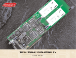
1
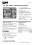
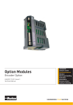
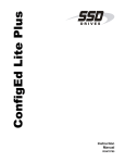
TS8000
Getting
Started
HA471056U001
© Copyright SSD Drives, Inc. 2004
All rights strictly reserved. No part of this document may be stored in a retrieval system, or
transmitted in any form or by any means to persons not employed by an SSD Drives
company without written permission from SSD Drives, Inc.
Although every effort has been taken to ensure the accuracy of this document it may be
necessary, without notice, to make amendments or correct omissions. SSD Drives cannot
accept responsibility for damage, injury, or expenses resulting there from.
Companies, names and data used as examples herein are fictitious unless otherwise
stated. All trademarks and copyrights are acknowledged as the property of their
respective owners.
Table Of Contents
TS8000 Getting Started
Table of Contents
Product Overview ............................................................................................ 3
General Description ....................................................................................... 3
Safety Information.......................................................................................... 4
Contents Of Package ..................................................................................... 4
Specifications .................................................................................................. 5
Power Requirements ....................................................................................... 5
Battery .......................................................................................................... 5
LCD Module Display ...................................................................................... 5
Keypad ......................................................................................................... 5
Touchscreen .................................................................................................. 5
Memory ........................................................................................................ 5
Communications ........................................................................................... 6
Environmental Conditions............................................................................... 6
Certifications And Compliances....................................................................... 6
Construction.................................................................................................. 7
Mounting Requirements .................................................................................. 7
Weight.......................................................................................................... 7
Dimensions ................................................................................................... 7
Installation And Power ...................................................................................... 9
Mounting Instructions ..................................................................................... 9
Connecting To Ground................................................................................... 9
Power Supply Requirements ............................................................................ 9
Communications ........................................................................................... 11
Configuring a TS8000.................................................................................. 11
Cables And Drivers ...................................................................................... 11
The CompactFlash Card............................................................................... 11
Ethernet Communications ............................................................................. 11
RS-232 Communications .............................................................................. 12
RS-422/485 Communications....................................................................... 13
Software / Unit Operations ............................................................................. 15
DSI8000 Software........................................................................................ 15
Keypad Buttons............................................................................................ 15
Front Panel LEDs.......................................................................................... 15
Display ....................................................................................................... 15
Touchscreen ................................................................................................ 16
Troubleshooting The TS8000 ........................................................................ 16
Battery And Time Keeping............................................................................. 16
Options And Accessories................................................................................. 19
Version 1.00.00
Page i
Table of Contents
TS8000 Getting Started
CompactFlash Socket ................................................................................... 19
Optional Communications Cards .................................................................. 19
Appendix A – TS8003 Specifications ................................................................. 21
TS8003 Dimensions ..................................................................................... 21
TS8003 Mounting Specifications .................................................................... 21
TS8003 Port Pin-Outs ................................................................................... 22
Appendix B – TS8006 Specifications ................................................................. 23
TS8006 Dimensions ..................................................................................... 23
TS8006 Mounting Specifications .................................................................... 23
TS8006 Port Pin-Outs ................................................................................... 24
Appendix C – TS8008 Specifications................................................................. 25
TS8008 Dimensions ..................................................................................... 25
TS8008 Mounting Specifications .................................................................... 25
TS8008 Port Pin-Outs ................................................................................... 26
Appendix D – TS8010 Specifications................................................................. 27
TS8010 Dimensions ..................................................................................... 27
TS8010 Mounting Specifications .................................................................... 27
TS8010 Port Pin-Outs ................................................................................... 28
Page ii
http://www.SSDdrives.com
Product Overview
TS8000 Getting Started
Product Overview
•
Configured with DSI8000 software.
•
3 onboard RS-232/422/485 comms ports.
•
Onboard 10/100 Base-T Ethernet for device comms,
web hosting, and unit networking.
•
USB Port to download configuration files or transfer
data from the unit.
•
4 Mb (TS8003, TS8006) or 8 Mb (TS8008, TS8010)
onboard flash memory (expandable with optional
CompactFlash card).
•
3.2 inch LCD display (TS8003) 128x64x2 color.
•
5.7 inch STN display (TS8006) 320x240x256 color.
•
7.7 inch DSTN display (TS8008) 640x480x256 color.
•
10.4 inch TFT display (TS8010) 640x480x256 color.
•
32 (TS8003), 5 (TS8006), 7 (TS8008), or 8 (TS8010)
button keypads for on screen menus.
•
24vdc power supply (+/- 20%).
•
Resistive Analog Touchscreen (TS8006, TS8008,
TS8010).
General Description
The TS8000 Operator Interfaces combine unique capabilities normally expected from
high-end units with a very affordable price. They are built around a high performance
core with integrated functionality. This core allows the TS8000 series to leverage many of
the features typically found in many PC based SCADA systems.
The TS8000 series are able to communicate with many different types of hardware using
high-speed RS-232/422/485 and 10/100 Base-T Ethernet communications ports. In
addition, the TS8000’s feature a USB port for fast download of configuration files and
access to trending and data logging. A CompactFlash socket is provided so that CF cards
can be used to collect your trends and data logs as well as to increase the memory
available for configuration files.
In addition to accessing and controlling of external resources, the TS8000 series allows a
user to easily view and enter information. Users can enter data through the touchscreen or
front panel keypad.
Page 3
http://www.SSDdrives.com
Product Overview
TS8000 Getting Started
Safety Information
All safety related regulations, local codes and instructions that appear in the manual or on
equipment must be observed to ensure personal safety and to prevent damage to either
the instrument or equipment connected to it. If equipment is used in a manner not
specified by the manufacturer, the protection provided by the equipment may be impaired.
Do not use the controller to directly command motors, valves, or other process actuators
not equipped with safeguards. To do so can be potentially harmful to persons or
equipment in the event of a fault to the controller.
Contents Of Package
The TS8000 unit will come shipped with the following additional equipment:
Page 4
•
TS8000 Operator Interface terminal
TS8008/00/00, or TS8010/00/00).
•
2 meter USB programming cable (CM471053).
•
5 meter serial communications cable (CM471054).
•
DSI8000 software CD with Value Added Apps (RI471055).
•
Getting Started bulletin (HA471056U000).
•
Panel cutout template.
•
Panel mounting hardware packet.
•
Panel mounting gasket.
•
Power supply terminal block.
(TS8003/00/00,
TS8006/00/00,
http://www.SSDdrives.com
Specifications
TS8000 Getting Started
Specifications
The following specifications pertain to the TS8000 series HMI. SSD Drives retains the right
to modify specifications at any time, without prior notice.
Power Requirements
+24vdc (+/- 20%) @ 9.5W max (TS8003), 14W max (TS8006), 24W max (TS8008), 33W
max (TS8010) - must use Class 2 or SELV rated power supply.
Power connection is available via removable 3-position terminal block.
Note: The TS8000’s “common” is not connected to the unit’s chassis. Refer to
“Connecting To Ground” in the “Installation And Power” section of this document.
Battery
Lithium CR2025 “button” cell. Typical lifetime of 10 years.
LCD Module Display
Model
TS8003
TS8006
TS8008
TS8010
Size
3.2 inch
5.7 inch
7.7 inch
10.4 inch
Type
FSTN
STN
DSTN
TFT
Colors
2 w. Backlight
256 QVGA
256 VGA
256 VGA
Pixels
128 x 64
320 x 240
640 x 480
640 x 480
Brightness
---
165 cd/m^2
120 cd/m^2
350 cd/m^2
Backlight *
---
20,000 Hour typ.
40,000 Hour typ.
50,000 Hour typ.
* Lifetime at room temperature.
Keypad
TS8003: 8 user legendable keys, 5 navigation keys, 12 numeric keys, 4 dedicated keys,
and 3 soft keys. TS8006: 5 keys for on-screen menus. TS8008: 7 keys for on-screen
menus. TS8010: 8 keys for on-screen menus.
Touchscreen
Resistive Analog Type (TS8006, TS8008, TS8010).
Memory
User: 4Mb (TS8003, TS8006) or 8Mb (TS8008, TS8010) onboard non-volatile flash
memory.
Memory Card: CompactFlash Type II slot for Type I and Type II CF cards.
Page 5
http://www.SSDdrives.com
Specifications
TS8000 Getting Started
Communications
USB Port: Adheres to USB 1.1 specification. Device only using Type B connection.
Serial Ports: Format and baud rates are individually programmable up to 115.2kb.
•
PGM Port: RS-232 port via RJ-12.
•
COMMS Ports: RS-232 port via RJ-12. RS-422/485 port via RJ-45.
•
DH485 TxEn: Transmit Enable; open collector, Voh = 15vdc, Vol = 0.5vdc @
25mA max).
Ethernet Port: 10/100 Base-T. RJ-45 jack is wired as a NIC.
Environmental Conditions
Operating Temperature Range: 0 to 50 deg C.
Storage Temperature Range: -20 to 70 deg C. (TS8003, TS8006) or 80 deg C. (TS8008,
TS8010)
Operating and Storage Humidity: 80% maximum relative humidity (non-condensing) from
0 to 50 deg C.
Altitude: Up to 2000 meters.
Certifications And Compliances
Safety: IEC 1010-1, EN 61010-1: Safety requirements for electrical equipment for
measurement, control, and laboratory use, Part 1.
IP66 enclosure rating (face only), IEC 529.
Type 4X enclosure rating (face only), UL50.
Electromagnetic Compatibility: Emissions and immunity to EN 61326: Electrical equipment
for measurement, control, and laboratory use, Part 1.
Immunity to industrial locations:
Electrostatic discharge
EN 61000-4-2 Criterion A
4 kV contact xchrg, 8 kV air xchrg
Electromagnetic RF fields
EN 61000-4-3 Criterion A
10 V/m
Fast transients (burst)
EN 61000-4-4 Criterion A
2 kV power, 2 kv signal
Surge
EN 61000-4-5 Criterion A
1 kV L-L, 2 kV L&N-E power
Page 6
http://www.SSDdrives.com
Specifications
TS8000 Getting Started
RF conducted interference
EN 61000-4-6 Criterion B
3 V/rms
Emissions:
Emissions
EN 55011
Class A
Notes: Criterion A (normal operation within specified limits), Criterion B (temporary loss of
performance from which the unit self recovers).
Construction
Steel rear metal enclosure with NEMA 4X / IP66 aluminum front plate when correctly fitted
with the provided gasket. Installation Category II, Pollution Degree 2.
Mounting Requirements
Maximum panel thickness is 0.25 inch (6.3 mm). For NEMA 4X / IP66 sealing, a steel
panel with a minimum thickness of 0.125 inch (3.17 mm) is recommended.
Maximum Mounting Stud Torque: 17 inch-pounds (1.92 N-m).
Weight
TS8003: 1.96 lbs (0.89 kg). TS8006: 3.00 lbs (1.36 kg). TS8008: 3.84 lbs (1.74 kg).
TS8010: 5.53 lbs (2.51 kg).
Dimensions
Refer to “Appendix A, B, C, and D - Dimensions” for individual unit dimensions.
Page 7
http://www.SSDdrives.com
Installation And Power
TS8000 Getting Started
Installation And Power
The following specifications pertain to the TS8000 series HMI. SSD Drives retains the right
to modify specifications at any time, without prior notice.
Mounting Instructions
This operator interface is designed for through-panel mounting. A panel cutout diagram
and a template are provided. Care should be taken to remove any loose material from
the mounting cut-out to prevent it from falling into the operator interface during
installation. A gasket is provided to enable sealing to NEMA 4X / IP66 specifications.
Install the provided nuts and tighten evenly for uniform gasket compression. For more
Detailed documentation, refer to “Appendix A, B, C, and D – Mounting Templates”.
Connecting To Ground
This protective conductor terminal is bonded to conductive parts of the equipment for
safety purposes and must be connected to an external protective grounding system.
Each TS8000 has a chassis ground terminal on the back of the unit. The unit
should be connected to ground. The chassis ground is not connected to the
signal common of the unit. Maintaining isolation between the ground and the
signal common is not required to operate the unit, however, other equipment
connected to this unit may require isolation between the ground and the signal common.
To maintain isolation between signal common and ground, care must be taken when
connections are made to the unit. For example, a power supply with isolation between its
signal common and ground must be used. Also, plugging in a USB cable may connect
signal common to ground.
Power Supply Requirements
The TS8003 requires a 24vdc power supply rated at 9.5W. The TS8006 requires a 24vdc
power supply rated at 14W. The TS8008 requires a 24vdc power supply rated at 24W.
The TS8010 requires a 24vdc power supply rated at 33W. The units may draw
considerably less than the rated power depending upon the options being used. As
additional features are used, the unit will draw increasing amounts of power. Items that
could cause increases are: additional communications, optional communications cards,
use of the CompactFlash card, and other features programmed through DSI8000.
In any case, it is very important that the power supply is mounted correctly if the unit is to
operate reliably. Please take care to observe the following points:
Page 9
•
The power supply must be mounted close to the unit, with usually not more than 6
feet (1.8 m) of cable between the supply and the operator interface. Ideally, the
shortest length possible should be used.
•
The wire used to connect the operator interface’s power supply should be at least
22 gauge wire. If a longer cable run is used, a heavier gauge wire should be
http://www.SSDdrives.com
Installation And Power
TS8000 Getting Started
used. The routing of the cable should be kept away from large contactors,
inverters, and other devices which may generate significant electrical noise.
•
Page 10
A power supply with a Class 2 or SELV rating should be used. A Class 2 or SELV
power supply provides isolation to accessible circuits from hazardous voltage
levels generated by a mains power supply due to single faults. SELV is an
acronym for “safety extra-low voltage.” SELV circuits exhibit voltage that are safe
to touch both under normal operating conditions and after a single fault, such as
a breakdown of a layer of basic insulation or after the failure of a single
component has occurred.
http://www.SSDdrives.com
Communications
TS8000 Getting Started
Communications
The following specifications pertain to the TS8000 series HMI. SSD Drives retains the right
to modify specifications at any time, without prior notice.
Configuring a TS8000
The TS8000 series are configured using DSI8000 software. DSI is included in the software
CD that comes packaged with each unit, or is also available from SSD Drives. Updates to
DSI8000 are posted on the SSD Drives website as they are made available. By
configuring the TS8000 using the latest version of DSI8000, you are assured that the unit
has the most up-to-date feature set. DSI software can configure the TS8000 through the
RS-232 PGM port, USB port, Ethernet Port, or the CompactFlash socket.
Cables And Drivers
The USB port is connected using a standard USB cable with a Type B connector. The
driver needed to allow your PC to access the USB port will be installed along with the
DSI8000 software. If this driver has not been installed, it can be downloaded from the
website.
The RS-232 PGM port uses a specialized cable to connect to the serial port of your PC. If
you choose to make this cable, refer to “Appendix A, B, C, and D - Port Pin-Outs” section
of this document for wiring information.
The CompactFlash Card
The CompactFlash card can also be used to program a TS8000 by placing a configuration
file and firmware on the CompactFlash card. The card is then inserted into the target
TS8000 and the unit is then powered on. Refer to the “DSI8000 User Manual”
(HA471055U001) for more information on this operation.
In order to transfer data from the CompactFlash card via the USB port, a driver must be
installed on your computer. This driver is installed with DSI8000 and is located in the
folder: C:\Program Files\SSD Drives\DSI8000\Device\. This may have already been
accomplished if the TS8000 was configured using the USB port.
Ethernet Communications
Ethernet communications can be established at either 10 Base-T or 100 Base-T speeds.
The TS8000 unit’s RJ-45 jack is wired as a true NIC (network interface card). For
example, when wiring to a hub or switch, use a straight-thru cable. When wiring to
another NIC, however, a cross-over cable must be used.
The Ethernet connector contains two LED’s. A yellow LED in the upper right corner, and a
bi-color (green / amber) LED in the upper left corner. The LED’s represent the following
status conditions:
Page 11
http://www.SSDdrives.com
Communications
TS8000 Getting Started
LED Color
Yellow (solid)
Yellow (flashing)
Description
Link established
Data transfer active
Green
10 Base-T communications
Amber
100 Base-T communications
Refer to the “DSI8000 User Manual” (HA471055U001) for additional information on
Ethernet communications.
RS-232 Communications
The TS8000 unit has two RS-232 ports: the PGM port, and the COMMS port. Although
only one of these ports can be used for programming, both ports can be used for remote
device communication. The RS-232 PGM port can be used for either master or slave
protocols with any TS8000 configuration.
Examples of RS-232 communications could involve another SSD Drives product, a PLC, or
a PC computer. By using a cable with RJ-12 ends on it, and a roll between Tx and Rx
wires, RS-232 communications with another TS8000 series touchscreen can be
established.
For RS-232 cable wiring between a TS8000 and a PC, refer to the following table:
RS-232 TS8000 To PC Connections
TS8010: RJ-12
Name
PC: DB-9
4
COM
1
5
Tx
2
2
Rx
3
n/c
4
3
COM
5
n/c
6
1
CTS
7
6
RTS
8
n/c
9
Page 12
Name
DCD
Rx
Tx
DTR
GND
DSR
RTS
CTS
RI
http://www.SSDdrives.com
Communications
TS8000 Getting Started
RS-422/485 Communications
The TS8000 has one RS-422/485 port. This port can be configured to act as either RS422 or RS-485, depending upon the user’s needs.
Page 13
http://www.SSDdrives.com
Software / Unit Operations
TS8000 Getting Started
Software / Unit Operations
The following specifications pertain to the TS8000 series HMI. SSD Drives retains the right
to modify specifications at any time, without prior notice.
DSI8000 Software
DSI8000 software is included with each purchase of a TS8000 unit, or it is also available
from SSD Drives. The latest updates to the software are always available from the SSD
Drives website.
Keypad Buttons
The TS8003 keypad consist of five unique key types: eight legendable keys, 5 navigational
keys, a 12 key numeric keypad, three soft keys for on screen menu selections, and four
keys labeled ALARMS, MUTE, EXIT, and MENU. The TS8006 keypad consist of five userassignable keys for on-screen menus. The TS8008 keypad consist of seven userassignable keys for on-screen menus. The TS8010 keypad consist of eight user-assignable
keys for on-screen menus.
Front Panel LEDs
There are three front panel LEDs. Shown below is the default status of each of the LEDs:
LED
Indication
Red LED - Power
Flashing
Unit is in the boot loader, no valid configuration is present.
Steady
Unit is powered and running an application.
Yellow LED – CF Card
Off
No CompactFlash card is present.
Steady
A valid CompactFlash card is present.
Flashing Rapidly
Unit is checking the CompactFlash card.
Flickering
Unit is writing to the CompactFlash card.
Flashing Slowly
An incorrectly formatted CompactFlash card is present.
Green LED - Alarm
Flashing
A tag is in an alarm state.
Steady
Valid configuration loaded and no alarms are present
Display
The TS8006, TS8008, and TS8010 use a liquid crystal display (LCD) for displaying text
and graphics. The display utilizes a cold cathode fluorescent tube (CCFL) for lighting the
display. The CCFL tubes can be dimmed for low light conditions.
These CCFL tubes have a limited lifetime. Backlight lifetime is based upon the amount of
time the display is turned on at full intensity. Turning the backlight off when the display is
Page 15
http://www.SSDdrives.com
Software / Unit Operations
TS8000 Getting Started
not in use can extend the lifetime of your backlight. This can be accomplished through the
DSI8000 software when configuring your unit.
Touchscreen
The TS8006, TS8008, and TS8010 utilize a resistive analog touchscreen for user input.
The unit will only produce an audible tone (beep) when a touch on an active touchscreen
cell in sensed. The touchscreen is fully functional as soon as the operator interface is
initialized, and can be operated with gloved hands.
Troubleshooting The TS8000
If for any reason you have trouble operating, connecting, or simply have questions
concerning your new TS8000, contact SSD Drives technical support.
Battery And Time Keeping
A battery is used to keep time when the unit is without power. Typical accuracy of the
TS8000 time keeping is less than one minute per month of drift. The state of the battery
does not in any way affect the unit’s program memory. All configurations are stored in
non-volatile flash memory.
Caution – Risk Of Electric Shock: The inverter board, attached to the
mounting plate, supplies the high voltage necessary to operate the
backlight. Touching the inverter board may result in injury. Please
exercise caution while working inside of the unit.
Caution: The circuit board contains static sensitive components. Before
handling the operator interface without the rear cover attached, discharge
static charges from your body by touching a grounded bare metal object.
Ideally, handle the operator interface at a static controlled, clean
workstation. Do not touch the surface areas of the circuit board. Dirt, oil,
or other contaminants may adversely affect circuit operation.
To change the battery of a TS8000, remove all power and other cabling from the unit.
Next, take off the unit’s rear cover by removing the five screws designated by the arrows
on the rear of the unit. Then, by lifting the top side, hinge the rear cover, thus providing
clearance for the connectors on the bottom side of the PCB as shown in the illustration
below. Remove the old battery from the holder and replace with a new one. The battery
used is a CR2025 lithium button cell. Assemble in the reverse order.
The following example depicts the battery replacement procedure for a TS8010.
Page 16
http://www.SSDdrives.com
Software / Unit Operations
Page 17
TS8000 Getting Started
http://www.SSDdrives.com
Options And Accessories
TS8000 Getting Started
Options And Accessories
The following specifications pertain to the TS8000 series HMI. SSD Drives retains the right
to modify specifications at any time, without prior notice.
CompactFlash Socket
The TS8000 is equipped with a Type II CompactFlash socket. This socket will accept either
Type I or Type II cards. Make sure to use cards with a minimum of 4Mb capacity. Cards
can be obtained at most computer and office supply retailers.
CompactFlash cards can be used for: configuration transfers, storage of larger
configurations, data logging, and trend storage.
Note: Do not remove or insert the CompactFlash card while power is applied to the unit.
Refer to the “Front Panel LEDs” section of this document for more information.
Information stored on a CompactFlash card can be read by a card reader attached to a
PC. This information is stored in a Windows compatible FAT-16 file format.
Optional Communications Cards
A communication card socket is provided for future communications cards. Visit the SSD
Drives website for information and availability of these cards.
Page 19
http://www.SSDdrives.com
Appendix A – TS8003 Specifications
TS8000 Getting Started
Appendix A – TS8003 Specifications
The following specifications pertain to the TS8003 series HMI. SSD Drives retains the right
to modify specifications at any time, without prior notice.
TS8003 Dimensions
TS8003 Mounting Specifications
Page 21
http://www.SSDdrives.com
Appendix A – TS8003 Specifications
TS8000 Getting Started
TS8003 Port Pin-Outs
Page 22
http://www.SSDdrives.com
Appendix B – TS8006 Specifications
TS8000 Getting Started
Appendix B – TS8006 Specifications
The following specifications pertain to the TS8006 series HMI. SSD Drives retains the right
to modify specifications at any time, without prior notice.
TS8006 Dimensions
TS8006 Mounting Specifications
Page 23
http://www.SSDdrives.com
Appendix B – TS8006 Specifications
TS8000 Getting Started
TS8006 Port Pin-Outs
Page 24
http://www.SSDdrives.com
Appendix C – TS8008 Specifications
TS8000 Getting Started
Appendix C – TS8008 Specifications
The following specifications pertain to the TS8008 series HMI. SSD Drives retains the right
to modify specifications at any time, without prior notice.
TS8008 Dimensions
TS8008 Mounting Specifications
Page 25
http://www.SSDdrives.com
Appendix C – TS8008 Specifications
TS8000 Getting Started
TS8008 Port Pin-Outs
Page 26
http://www.SSDdrives.com
Appendix D – TS8010 Specifications
TS8000 Getting Started
Appendix D – TS8010 Specifications
The following specifications pertain to the TS8010 series HMI. SSD Drives retains the right
to modify specifications at any time, without prior notice.
TS8010 Dimensions
TS8010 Mounting Specifications
Page 27
http://www.SSDdrives.com
Appendix D – TS8010 Specifications
TS8000 Getting Started
TS8010 Port Pin-Outs
Limited Warranty
SSD Drives warrants the goods against defects in design, materials, and
workmanship for the period of 12 months from the date of delivery on the terms
detailed in SSD Drives Standard Conditions of Sale IA058393C.
SSD Drives reserves the right to change the content and product specification
without notice.
Page 28
http://www.SSDdrives.com
UK
SSD Drives Ltd
New Courtwick Lane
Littlehampton
West Sussex BN17 7RZ
Tel: +44 (0)1903 737000
Fax: +44 (0)1903 737100
CANADA
SSD Drives Inc
880 Laurentian Drive
Burlington
Ontario L7N 3V6
Tel: +1 (905) 333 7787
Fax: +1 (905) 632 0107
CHINA
SSD Drives Ltd
Room 1603, Hua Teng Edifice
302# Jin Song San Qu
Chaoyang District,
Beijing 100021
P.R. China
DENMARK
SSD Drives AB
Enghavevej 11
DK-7100
Vejle
Tel: +45 (0)70 201311
Fax: +45 (0)70 201312
FRANCE
SSD Drives SAS
15 Avenue de Norvège
Villebon sur Yvette
F-91953 Courtaboeuf Cedex
Paris
Tel: +33 - 1 69 18 51 51
Fax: +33 - 1 69 18 51 59
GERMANY
SSD Drives GmbH
Von-Humboldt-Strasse 10
64646 Heppenheim
Tel: +49 (6252) 798200
Fax: +49 (6252) 798205
ITALY
SSD Drives SPA
Via Gran Sasso 9
20030 Lentate Sul Seveso
Milano
Tel: +39 (0362) 557308
Fax: +39 (0362) 557312
SWEDEN
SSD Drives AB
Montörgaten 7, SE-302 60
Halmstad
Tel: +46 (0)35-17 73 00
Fax: +46 (0)35-10 84 07
U.S.A.
SSD Drives Inc
9225 Forsyth Park Drive
Charlotte
North Carolina 28273
Tel: +1 (704) 588 3246
Fax: +1 (704) 588 3249
01/11/04
Local availability and service support also in:
ARGENTINA • AUSTRALIA • AUSTRIA • BELGIUM • BRAZIL • CHILE • CHINA • COLOMBIA • CYPRUS
CZECH REPUBLIC • EGYPT • GREECE • HONG KONG • HUNGARY • ICELAND • INDONESIA • IRAN
IRELAND • ISRAEL • JAPAN • KENYA • KOREA • LITHUANIA • MALAYSIA • MOROCCO • NETHERLANDS
NEW ZEALAND • NORWAY • PHILIPPINES • POLAND • PORTUGAL • ROMANIA • SINGAPORE • SOUTH AFRICA
SPAIN • SWITZERLAND • TAIWAN • THAILAND • TURKEY • UNITED ARAB EMIRATES
Local Address
www.SSDdrives.com
*HA471056U001*
TS8000 Getting Started